Magnetically assisted fast ignition
W.-M. Wang,1, 2,∗ P. Gibbon,1
Z.-M. Sheng,3, 4, 5
and Y.-T. Li2, 5
1Forschungzentrum J¨ulich GmbH, Institute for Advanced Simulation,
J¨ulich Supercomputing Centre, D-52425 J¨ulich, Germany
2Beijing National Laboratory for Condensed Matter Physics, Institute of Physics, CAS, Beijing 100190, China
3SUPA, Department of Physics, University of Strathclyde, Glasgow G4 0NG, United Kingdom
4
Key Laboratory for Laser Plasmas (MoE) and Department of Physics and Astronomy,
Shanghai Jiao Tong University, Shanghai 200240, China
5IFSA Collaborative Innovation Center,
Shanghai Jiao Tong University, Shanghai 200240, China
(Dated: December 15, 2014)
Abstract
Fast ignition (FI) is investigated via integrated particle-in-cell simulation including both
gen-eration and transport of fast electrons, where petawatt ignition lasers of 2 picoseconds (ps) and compressed targets with peak density 300 g cm−3 and areal density 0.49 g cm−2 at the core are taken. When a 20 megagauss static magnetic field is imposed across the cone-free target, the energy coupling from the laser to the core is enhanced by 7-fold and reaches 14%. This value even exceeds
that obtained using a cone-inserted target, suggesting that the magnetically assisted scheme may be a viable alternative for FI. With this scheme, it is demonstrated that two counter-propagating,
6 ps, 6 kJ lasers along the magnetic field transfer 12% their energy to the core, which is then heated to 3 keV.
Fast ignition (FI) scheme with its potential for reducing the driver energy requirements in laser fusion has been very attractive but also has brought huge technical challenges since proposed 20 years ago [1]. It requires that large amount of collimated fast electrons of MeV are transported over 100µm distance in coronal plasma to heat a high-density core at 300g cm−3, where the fast electrons are generated by a 10ps petawatt (PW) ignition laser. The key remaining issue is how to achieve a reasonable coupling above 10% from the laser to the core. Up to 20% coupling from a 0.6ps ignition laser was demonstrated experimentally in 2001 [2] with a cone-inserted target to reduce the transport distance of the electrons to the core. However, a few subsequent experiments with longer duration ignition lasers between 2008 and 2011 reported much lower coupling at Vulcan [3], Omega EP [4], and GEKKO XII systems [5], respectively. The large difference in the coupling was not completely understood, but could be related to different preplasmas formed by the ignition laser prepulses in the cones [3–5]. A commonly acknowledged factor causing the low coupling in these experiments [3–5] is large divergence of the fast electrons generated in the cones [6, 7]. Divergence angles up to 50◦ were found in many studies [7–9].
nanosecond-laser-driven capacitor-coil experiments [14].
We first take 2ps ignition lasers to compare the coupling among the original, cone-inserted, and magnetically assisted (MA) schemes. The simulations are implemented by the two-dimensional (2D) KLAPS with a two-system PIC model developed recently [10]. Fast electron generation via laser-plasma interaction is simulated by a conventional PIC system. When the fast electrons transport to the region with the plasma density 200nc (nc = 1.1×1021 cm−3) or to the cone tip in the cone-inserted scheme, where is far away from the laser interaction zone, the data of these fast electrons are copied in real time to a second PIC system with a reduced field solver as used in the two-region PIC [15] and hybrid PIC [16]. We define the fast electrons with energy above 0.1MeV and forward momentum
px >0.45mec(50keV). The second PIC system calculates the subsequent transport of these electrons in real target density (with a pedestal of 198nc), as shown in Figs. 1(a)-1(c). In both systems macroparticles are taken to denote the plasma and Coulomb collision [17] and 4th-order current calculation [10] is included. In the conventional system, if the density is above 200nc, it is lessened artificially to this value to reduce numerical noise [10].
We take tritium targets instead of DT targets since fusion processes are not considered. The targets in the three schemes are shown in Figs. 1(a)-1(c), with an uniform density 300g cm−3 (54000nc) within a circle of radius 10µm and the surrounding density decreasing exponentially with scalelength 9µm along the radial direction. The critical density layer is located at 108µm away from the target center. We define the area above 100g cm−3 as the core with areal density 0.49g cm−2. Implosion simulations [18] show the plasma temperature is within 0.3-1keV. For simplicity we employ an uniform temperature 1keV for electrons and ions. In Figure 1(a) a cone is used with wall depth 5µm, density 200nc, tip size 20µm, and inner length 20µm. The cone opening angle 30◦ and the distance 35µm between
the tip to target center approach the experimental parameters [3–5]. To allow for prepulse effects, a preplasma is taken inside the cone with an exponential profile with scalelength 2µm along the x-direction (our simulation shows the laser-to-core coupling is reduced by 25% with the increased scalelength 4µm, which approaches the experimental result in [4]). A 0.63-kJ ignition laser propagates along the +x-direction with wavelength 1µm and electric field Ey = a0exp(−y2/r02)f(ξ) sin(2πξ), where a0 = 12.1 corresponding to 2×10²⁰W/cm2,
case) in x×y directions is taken in the two PIC systems. The spatial resolution is 0.02µm. In the conventional system 49 electrons and ions per cell are taken to control the noise; 25 in the second system.
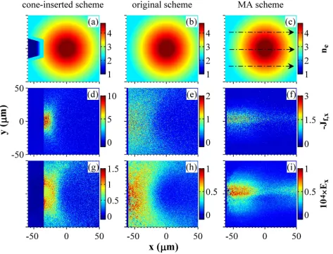
Figures 1(d)-1(f) show fast-electron currents with the three schemes in the second PIC system. With the original scheme the fast electrons diffuse in the whole transverse space in the y-direction [see Fig. 1(e)] due to large divergence. With a cone inserted, a strengthened current is distributed in reduced transverse space [Fig. 1(d)]. Most strikingly, when a 20 megagauss static B-field is applied to the cone-free target along the x-direction [Fig. 1(c)], the fast-electron current is confined around the axis within a narrower transverse space [Fig. 1(f)] than the cone-inserted scheme. The current in Fig. 1(f) is weaker than that in Fig. 1(d) because the former is distributed in a larger longitudinal space and composed of less electrons with higher energy, as discussed below. Resistive electric fields consistent with the currents are plotted in Figs. 1(g)-1(i), which have the similar patterns to the currents. In Fig. 1(i) the field vanishes at the region far away from the axis (y=0), in contrast to Fig. 1(g). This suggests fewer electrons escape transversely away from the simulation box in the MA scheme. By contrast, more electrons escape longitudinally after they travel through the target center, according to the field distributed at x >0 in Fig. 1(i).
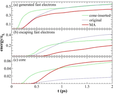
Figure 2(b) displays the energy of the escaping fast electrons with time. In the MA scheme the escaping electron fraction is reduced considerably compared with the other two schemes. Whereas, this does not bring much advantage in the laser-to-core coupling shown in Fig. 2(c): 6.2% for the MA scheme at 2ps and 5.6% for the cone-inserted scheme. There are two main reasons. First the intensity 2×10²⁰ W/cm2 used is too high for the cone-free target, in which the average energy of the fast electrons generated is 4.8MeV (counted at
x = −60µm where fast electrons are injected to the second system). This energy is far above 1.2MeV (counted at the injection point x = −35µm) in the cone-inserted case, due to the larger density scalelength 9µm in the MA scheme compared to the preplasma density scalelength 2µm in the cone [19]. Therefore the fast electrons escape mainly longitudinally in the MA scheme, as shown in Table I. In fact, this laser intensity has been optimized for the cone-inserted scheme according to Ref. [20]. The authors found that the laser-to-core coupling is nearly unchanged with growing intensity at relatively low values and falls at higher intensities. A similar result is shown in Table I with an optimal intensity at 2×10²⁰ W/cm2. A second reason is: the coupling to the fast electrons (p
reduced with the B-field [see Fig. 2(a) and Table I]. Our simulations show that the B-field causes stronger hole boring [19] and more laser energy is reflected or scattered by the plasma with higher density. These reflected and scattered light beams can generate hot electrons largely deviating from (even opposite to) the +x-direction.
TABLE I. Energy coupling (percentage) from the laser to the core ηcore and to the fast electrons ηf ast, and the laser reflectivity Rat different intensities (W/cm2) when original, cone-inserted, and
MA schemes are taken, respectively. escape is the energy of all the escaping fast electrons and escape⊥is that escaping transversely. These values are obtained at 2ps. Each simulation takes 0.8 million core-hours in average on JUQUEEN.
Scheme intensity ηcore ηf ast escape escape⊥ R
original 5×10¹⁹ 2.1 51.2 38.1 26.2 6.8
original 2×10²⁰ 1.6 53.8 40.9 28.1 6.2 cone-inserted 1×10²⁰ 5.7 50.6 27.4 14.5 27.0
cone-inserted 2×10²⁰ 5.6 55.2 30.8 15.2 24.2
cone-inserted 4×10²⁰ 4.6 53.8 33.6 17.1 20.1
MA 5×10¹⁹ 13.9 48.2 16.4 0.08 13.6
MA 1×10²⁰ 10.0 48.6 19.3 0.09 10.4
MA 2×10²⁰ 6.0 43.1 19.8 1.4 9.3
To optimize the laser-to-core coupling for the MA scheme, we decrease the laser intensity to reduce the electron energy. The coupling enhances continuously and reaches 13.9% at 5×10¹⁹
W/cm2
(Table I) with average electron energy 2.9MeV. It should grow with further decrease in the intensity. Considering that PW-scale ignition lasers will be adopted in real experiments, laser intensities should not be too low. To achieve high coupling with relatively high intensities, one can employ 2ω or 3ω lasers since the electron energy scales approximately linearly with the laser wavelength [21, 22].
In further simulation, we take 2ω lasers at 2× 10²⁰
W/cm2
are not changed. This simulation takes 3 million core-hours on JUQUEEN.
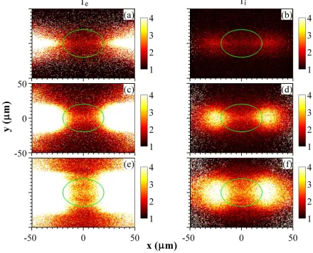
Figure 3 shows the target temperatures at different times, where the core is marked by a circle. It illustrates the process of the core heating by two counter-propagating fast-electron influxes, as shown in Fig. 4. Because the influxes are directed, the heating front always appears around the axis, which is favorable for the heating to the core. At 2ps the core periphery starts to be heated [Fig. 3(a)]. At 6ps the whole core has been obviously heated [Fig. 3(e)] and the average electron temperature reaches 3keV [Fig. 5(c)]. Note that the fast electrons are included to calculate the temperatures in Figs. 3 and 5(c). Following the electron heating, the ions are also heated as observed in Figs. 3(b), 3(d), and 3(f). At 6ps the average ion temperature at the core is 2.8keV [Fig. 5(c)]. At this time the coupling from the two lasers to the core is 12%, as shown in Fig. 5(b).
A double-lobe pattern is observed in the ion temperature distributions, i.e., the ions are preferentially heated at two symmetric regions outside the core and inside the two injection points (x=±60µm). The reason is as follows. The plasma density is relatively low around the injection points and the fast electrons have too high energy here at earlier time, as seen in Fig. 5(c). Hence collisions between these electrons and background ions are weak. With transport of these electrons towards the target center, their energy is reduced gradually, the plasma density grows, and therefore the collisions become stronger. On the other hand, in the lower-density region the temperature enhancement shows more remarkable if the same energy is absorbed. Thus the hottest regions appear between the injection points and the target center. With the fast electron energy decreases continuously as observed in Fig. 5(c), the hottest regions spread towards the injection points as seen in Fig. 3(f). Meanwhile, the temperature around the target center shows obvious enhancement due to temporal accumulation of energy absorption.
heat the target more efficiently and therefore, the coupling to the target and core does not decrease, as shown in Fig. 5(b).
Note that the fast-electron currents are computed also with the background electrons above 5 times local temperature. Thus the currents become wider with time in Fig. 4. One notices in Figs. 4(d) and 4(f) that the fields at peripheries are stronger because the two counter-propagating influxes with higher-energy electrons around the axis travel through the target center and counteract. Besides, our simulations show that collisions dominates completely over ohmic heating, as observed in hybrid-PIC simulations [6]. Contribution of self-generated fields (including the azimuthal B-field) from the beam to the core heating is slight.
We have taken 2D simulations. This is expected to cause small difference in the laser-to-core coupling compared to 3D simulations due to the symmetry of transverse electron motion under the B-field, i.e., if electrons hit on the core at a 2D circle, they can reach the corresponding 3D sphere. Also, our simulations do not include implosion and therefore the evolution of the imposed B-field topology and the target conditions are not considered. Simply we have used the initial B-field topology, which could be suitable if the B-field can be imposed shortly before the ignition laser incidence. Besides, we have taken the injection point at 200nc to meet the conditions of the two-system approach: it is far away from the laser interaction zone; the density here should be sufficiently high to satisfy the field solver in the second system; the density should also be low enough to avoid the noise in the conventional system.
In summary, we have demonstrated high laser-to-core coupling through a static B-field imposed on a cone-free target with integrated PIC simulations. The coupling reaches 14% at a slightly optimized laser intensity, compared to 2% without the B-field. This is attributed to the constrained fast-electron motion along the B-field. The coupling with the cone-inserted target is 6% at an optimized laser intensity and without considering implosion asymmetry. We have shown that the high coupling via the MA scheme can maintain for 6ps with 2ω
ignition lasers. The coupling could be enhanced further provided 3ω lasers are taken to reduce the fast-electron energy further.
supported by the National Basic Research Program of China (Grants No. 2013CBA01500) and NSFC (Grants No. 11375261, 11105217, 11421064, 11129503, and 113111048).
[1] M. Tabak, J. Hammer, M. Glinsky, W. Kruer, S. Wilks, J. Woodworth, E. Campbell, M.
Perry, and R. Mason, Phys. Plasmas 1, 1628 (1994).
[2] R. Kodama, P. A. Norreys, K. Mima, A. E. Dangor, R. G. Evans, H. Fujita, Y. Kitagawa, K.
Krushelnick, T. Miyakoshi, N. Miyanaga et al., Nature (London) 412, 798 (2001).
[3] M. H. Key, J. C. Adam, K. U. Akli, M. Borghesi, M. H. Chen, R. G. Evans, R. R. Freeman,
H. Habara, S. P. Hatchett, J. M. Hill et al., Phys. Plasmas 15, 022701 (2008).
[4] W. Theobald, A. A. Solodov, C. Stoeckl, K. S. Anderson, R. Betti, T. R. Boehly, R. S.
Craxton, J. A. Delettrez, C. Dorrer, J. A. Frenje et al., Phys. Plasmas 18, 056305 (2011). [5] H. Shiraga, S. Fujioka, M. Nakai, T. Watari, H. Nakamura, Y. Arikawa, H. Hosoda, T. Nagai,
M. Koga, H. Kikuchi et al., Plasma Phys. Controlled Fusion 53, 124029 (2011). [6] J. Honrubia and J. Meyer-ter-Vehn, Nucl. Fusion 46, L25 (2006).
[7] D. J. Strozzi, M. Tabak, D. J. Larson, L. Divol, A. J. Kemp, C. Bellei, M. M. Marinak, and M. H. Key, Phys. Plasmas 19, 072711 (2012).
[8] R. B. Stephens, R. A. Snavely, Y. Aglitskiy, F. Amiranoff, C. Andersen, D. Batani, S. D. Baton, T. Cowan, R. R. Freeman, T. Hall et al., Phys. Rev. E 69, 066414 (2004).
[9] Z.-M. Sheng, Y. Sentoku, K. Mima, J. Zhang, W. Yu, and J. Meyer-ter-Vehn, Phys. Rev. Lett. 85, 5340 (2000).
[10] W.-M. Wang, P. Gibbon, Z.-M. Sheng, Y.-T. Li, Integrated simulation approach for
laser-driven fast ignition, submitted to Phys. Rev. E (http://arxiv.org/abs/1409.1808).
[11] C. Stoeckl, T. R. Boehly, J. A. Delettrez, S. P. Hatchett, J. A. Frenje, V. Yu. Glebov, C. K. Li, J. E. Miller, R. D. Petrasso, F. H. Seguin et al., Plasma Phys. Controlled Fusion 47, B856
(2005).
[12] H.-B. Cai, S.-P. Zhu, and X. T. He, Phys. Plasmas 20, 072701 (2013).
[13] P. Y. Chang, G. Fiksel, M. Hohenberger, J. P. Knauer, R. Betti, F. J. Marshall, D. D. Meyerhofer, F. H. Seguin, and R. D. Petrasso, Phys. Rev. Lett. 107, 035006 (2011).
Yamamoto, H. Nakashima, T. Watanabe et al., Sci. Rep.3, 1170 (2013). [15] B. I. Cohen, A. J. Kemp and L. Divol, J. Comp. Phys.229, 4591 (2010).
[16] A. R. Bell, J. R. Davies, S. Guerin and H. Ruhl, Plasma Phys. Control. Fusion39, 653 (1997). [17] Y. Sentoku and A. J. Kemp, J. Comp. Phys. 227, 6846 (2008).
[18] J. J. Honrubia, J. Quant. Spectrosc. Radiat. Transfer49, 491 (1993).
[19] P. Gibbon,Short Pulse Laser Interactions with Matter(Imperial College Press, London, 2000).
[20] B. Chrisman,Y. Sentoku, and A. J. Kemp, Phys. Plasmas15, 056309 (2008).
[21] S. C. Wilks, W. L. Kruer, M. Tabak, and A. B. Langdon, Phys. Rev. Lett. 69, 1383 (1992).
[22] Y.-Q. Cui, W.-M. Wang, Z.-M. Sheng, Y.-T. Li and J. Zhang, Plasma Phys. Control. Fusion
Figure Captions
Fig. 1. (Color online) Snapshots of electron densities lg(ne/nc) at initial time (first row), fast-electron currents Jf,x/encc at 2ps (second row), and resistive electric fields 104
×eEx/meωc at 2ps (third row). The three columns correspond to the cone-inserted, original, and MA schemes, respectively.
Fig. 2. (Color online) Temporal evolution of fractional energy of the fast electrons (a) generated from laser interaction, (b) escaping from the simulation box, and (c) absorbed by the core, normalized by the laser energy εL. Different lines in each plot correspond to the cone-inserted, original, and MA schemes, respectively.
Fig. 3. (Color online) Snapshots of temperatures (keV) of electrons (left column) and ions (right column). The three rows correspond to 2ps, 4ps, and 6ps, respectively. The core is marked with the green circle in each plot.
Fig. 4. (Color online) Snapshots of fast-electron currents (encc) in the left column and resistive electric fields (meωc/e) in the right column. The three rows correspond to 2ps, 4ps, and 6ps, respectively.