Rochester Institute of Technology
RIT Scholar Works
Theses Thesis/Dissertation Collections
7-1-2012
A computational study of the effects of adherent
leukocytes on secondary recruitment
Dhananjay Subramaniam
Follow this and additional works at:http://scholarworks.rit.edu/theses
This Thesis is brought to you for free and open access by the Thesis/Dissertation Collections at RIT Scholar Works. It has been accepted for inclusion in Theses by an authorized administrator of RIT Scholar Works. For more information, please [email protected].
Recommended Citation
A computational study of the effects of adherent leukocytes on
secondary recruitment
by
Dhananjay Radhakrishnan Subramaniam
A Thesis Submitted in Partial Fulfillment of the Requirements for the Degree of Master of Science in Mechanical Engineering
Supervised by
Dr. David J. Gee
Department of Mechanical Engineering Kate Gleason College of Engineering
Rochester Institute of Technology Rochester, NY
July 2012
Approved By:
Dr. David J. Gee
Department of Mechanical Engineering ______________________________
(Thesis Advisor)
Dr. Risa J. Robinson
Department of Mechanical Engineering ______________________________
(Committee Member)
Dr. Kathleen A. Lamkin-Kennard
Department of Mechanical Engineering ______________________________
(Committee Member)
Dr. Alan H. Nye
Department of Mechanical Engineering ______________________________
© Copyright 2012 by Dhananjay Radhakrishnan Subramaniam
Acknowledgements
Firstly, I would like to thank my advisor, Dr. David J. Gee for his valuable support and
encouragement throughout my graduate study. His passion and dedication towards inflammation
modeling has fueled my interest and appreciation towards the field of computational biology. I
would like to convey my gratitude to him for his excellent guidance and this wonderful
opportunity to conduct research in an interdisciplinary field of study.
Secondly, I would like to thank Dr. Sangtae Kim (Executive Director - Morgridge
Institute for Research) for several discussions concerning micro-hydrodynamics, Dr. Michael R.
King (Associate Professor – Biomedical Engineering, Cornell University) for his valuable
suggestions related to adhesive interactions, Dr. Edward C. Hensel, Dr. Risa J. Robinson, Dr.
Kathleen A. Lamkin-Kennard for backing this study, Diane Selleck, Diedra Livingston, Venessa
Mitchell and Jill Ehmann of the ME Department for their help and support throughout my
studies.
Finally, I would like to thank my parents Dr. S. Radhakrishnan and Ananthalakshmi
Radhakrishnan, my aunt Dr. Kumari Santosh, elder sister Kirthi and cousins Sadashiv, Shrihari
and Vidya for their constant support and encouragement, which has kept me cheerful and
motivated during my tenure as a graduate student at RIT.
Partial support from the Office of Vice President for Research (#15651) and
Abstract
Leukocyte rolling is known to be mediated by the selectin family of adhesion molecules and
their corresponding ligands and is characterized by the formation and breakage of
receptor-ligand bonds. Selectin mediated rolling is associated with the initial stages of the leukocyte
adhesion cascade (LAC) in which the cell passes through several stages including
chemo-attraction, rolling adhesion, tight adhesion and transmigration before moving out of the
circulatory system towards the site of injury. This thesis studies the initial stages of the leukocyte
adhesion cascade through a direct numerical simulation based on boundary element techniques.
Besides, cell deformation during rolling is believed to further enhance rolling interactions. This
feature is accounted for by implementing a constitutive model that qualitatively represents the
morphology of white blood cells in the early stages of selectin mediated rolling. This research
describes the contribution of contact mechanics towards modulation in the contact area for cell
substrate interactions. The results predict that compliant cells could roll slower (~ 25%) as
compared to their stiffer counterparts. The effect of variations in cell size and bond compression
on the decrease in the translational velocity as well as the inherent noisiness in the translational
velocity is investigated.
The latter part of this thesis attempts to quantify hydrodynamic recruitment of leukocytes
with a view to providing insights into cell trafficking in physiological phenomena such as the
homing of stem cells towards bone marrow. In vivo experimental data of leukocyte
accumulations during exposure to Zymosan-Activated Serum (ZAS) in rabbits and immune
response in hamster cheek pouches appears to reinforce this hypothesis. The influence of
with deformed adherent cells are computed through a series of glancing collisions in order to
Table of Contents
CHAPTER 1: INTRODUCTION
1.1Immune Response 1
1.2Mathematical Modeling of Blood Flow 2
1.3Modeling Biochemistry 5
1.4Leukocyte Trafficking 6
1.5Novelties in Proposed Research 6
1.6Statement of Work 7
1.7Thesis Objectives and Scope 8
CHAPTER 2: THEORETICAL MODEL
2.1Problem Formulation 9
2.2Boundary Element Method 10
2.3Numerical Validation 18
CHAPTER 3: SHORT RANGE NON-ADHESIVE INTERACTIONS
3.1Van Der Waal’s Interactions 30
3.2Lubricated Collisions 31
3.3Numerical Validation 33
CHAPTER 4: ADHESIVE INTERACTIONS
4.1Modeling Biochemistry 37
4.2Interfacial Compression 38
4.3Numerical Validation 41
CHAPTER 5: RECRUITMENT OF IMMUNE CELLS
5.1Overview of Physiological Problem 52
5.2Past Numerical Studies; Modeling Deformable Cells 53
5.3Results 55
CHAPTER 6: CONCLUSIONS AND FUTURE DIRECTIONS 76
Bibliography 79
Appendix A: Half Space Green’s Functions 85
Appendix B: Supplementary Trembling Results 88
List of Figures
Fig. 1.1: The Leukocyte Adhesion Cascade. 1
Fig. 1.2: Structure of neutrophils. 2
Fig. 1.3: Scanning Electron Micrograph (SEM) of a white blood cell. 3
Fig. 1.4: Leukocyte modeled as a linear elastic solid. 5
Fig. 2.1: Elastically deformable particles in wall bounded shear (Couette) flow. 9
Fig. 2.2: Method of reflections to satisfy boundary conditions of no-slip
and no-displacement boundary conditions at rigid substrate. 14
Fig. 2.3: QUAD9 Lagrangian element. 18
Fig. 2.4: 96 element discretization of (a) sphere (b) oblate spheroid. 19
Fig. 2.5: Comparison between the trajectories of a buoyant and dense
spherical inclusion (a = 5 µm, η = 1 Pa, ν = 0.33,γ& = 100, 200 s-1). 20
Fig. 2.6: Comparison between the trajectories of a buoyant and dense oblate
spheroid inclusion (a = 5 µm, η = 1 Pa, ν = 0.33, α = π/2, κ = 0.75,γ& = 100 s-1). 21
Fig. 2.7: Comparison between the trajectories of a buoyant and dense oblate
spheroid inclusion (a = 5 µm, η = 1 Pa, ν = 0.33, α = π/2, κ = 0.5,γ& = 100 s-1). 21
Fig. 2.8: Comparison between the trajectories of a buoyant and dense oblate
spheroid inclusion (a = 5 µm, η = 1 Pa, ν = 0.33, α = π/2, κ = 0.5,γ& = 100, 200 s-1). 22
Fig. 2.9: Deformed shape of a spherical inclusion in a shear flow. 23
Fig. 2.10: Steady state shapes of a deformable spherical inclusion in the
proximity of a rigid wall. For both simulations a = 5 µm,γ& = 100 s-1,
ν = 0.33: (a), (b) η = 0.5 Pa (c), (d) η = 23 Pa. 23
Fig. 2.11: Tank treading sequence of a deformable spherical inclusion in the
proximity of a rigid wall (a = 5 µm, η = 1 Pa, ν = 0.33,γ& = 100 s-1). 24
Fig. 2.12: Advection of material points along the perimeter of an ellipse. 25
Fig. 2.13: Tumbling sequence of a deformable oblate spheroid in the proximity
of a rigid wall (a = 5 µm, η = 1 Pa, ν = 0.33, α = π/2, κ = 0.5,γ& = 100 s-1). 26
Fig. 2.14: Tumbling sequence of a deformable oblate spheroid in the proximity
Fig. 3.1: Lubricated collisions between two spherical cells in the proximity
of the reactive substrate. For both simulations a = 5 µm,γ& = 100 s-1, ν = 0.33:
(a) stiff particles, η = 8 kPa (b) relatively more compliant particles, η = 4 kPa. 34
Fig. 3.2: Lubricated collisions between elastic spheres. 34
Fig. 3.3: Variation in shear (□) and squeeze components (◊) of lubrication
with increasing cell-cell separation. 35
Fig. 3.4: Trajectories of free-stream cells undergoing binary collisions in
the proximity of the reactive substrate. 35
Fig. 4.1: Interfacial compression of an elastic sphere contacting a rigid wall. 39
Fig. 4.2: Force and torque balance on a tethered cell. 40
Fig. 4.3: Tethered cells (a) compressed, compliant (η = 0.508 kPa, ν = 0.33)
(b) rigid, a = 5 µm. 43
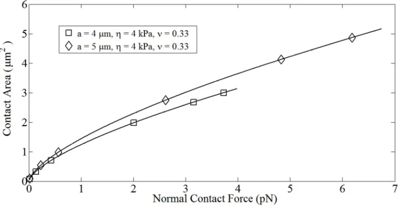
Fig. 4.4: Variation in contact area of compliant (◊) and stiff (□) cells with time. 43
Fig. 4.5: Variation in contact area of compliant (◊) and stiff (□) cells with
normal contact force. 44
Fig. 4.6: Drop in the translational velocities of stiff and compliant cells
with time. For all simulations a = 5 µm,γ& = 100 s-1, ν = 0.33: cell compliance
η = 0.508, 1 kPa. 44
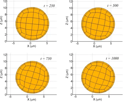
Fig. 4.7: Rolling sequence of a moderately compliant cell (η = 4 kPa,
ν = 0.33,
σ
= 0.5 dyne/cm, a = 5 µm). 45Fig. 4.8: Rolling sequence of a relatively stiff cell (η = 10 kPa,
ν = 0.33,
σ
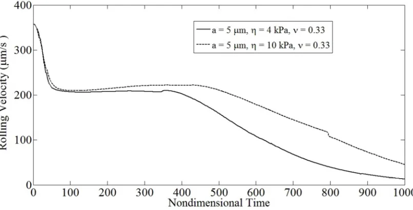
= 0.5 dyne/cm, a = 5µm). 46Fig. 4.9: Drop in the translational velocities of cells of identical dimensions
and varying compliance with time. For both simulations a = 5 µm,γ& = 100 s-1,
ν = 0.33: cell compliance η = 4, 10 kPa. 47
Fig. 4.10: Drop in the translational velocities of cells of identical compliance
and varying dimensions with time. For both simulations η = 4 kPa,γ& = 100 s-1,
ν = 0.33: cell characteristic radius a = 4, 5 µm. 47
Fig. 4.11: Variation in contact area for cells with identical compliance and
simulations η = 4 kPa,γ& = 100 s-1, ν = 0.33. 48
Fig. 4.12: Drop in translational velocities for a compliant cell with adhesive
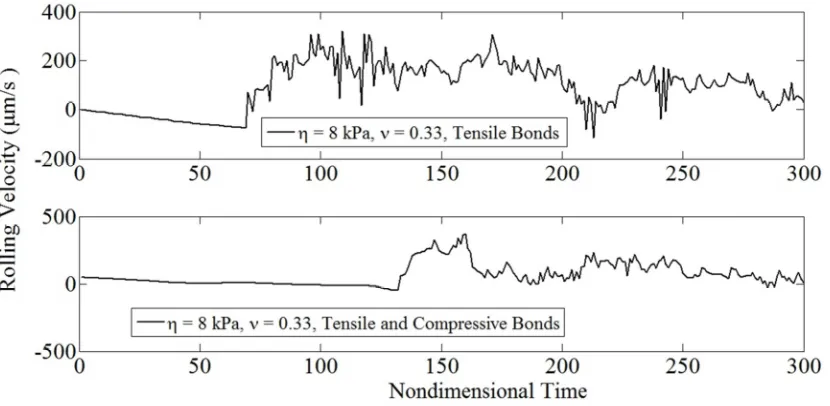
bonds loaded in tension or compression. For both simulations η = 8 kPa,γ& = 100 s-1,
ν = 0.33: upper panel – tensile bond forces, lower panel - tensile and
compressive bond forces. 49
Fig. 4.13: Noisy rolling for a compliant cell with adhesive bonds
loaded in tension or compression. For both simulations η = 8 kPa,γ& = 100 s-1,
ν = 0.33: upper panel – tensile forces, lower panel - tensile and
compressive bond forces. 50
Fig. 4.14: Time varying contact area for a compliant cell with adhesive bonds
loaded in tension or compression. For both simulations η = 8 kPa,γ& = 100 s-1,
ν = 0.33: upper panel – tensile forces, lower panel - tensile and
compressive bond forces. 50
Fig. 5.1: 96 element discretization of (a) moderately deformed
(b) highly deformed cells. 56
Fig. 5.2: Binary interaction between a firmly adherent, spherical cell
and a spherical free-stream cell (δx = -9 µm, δy = 2 µm, δz = 7.75 µm,
a = 5 µm,γ& = 100 s-1). 57
Fig. 5.3: Cell trajectories for binary interactions involving a firmly
adherent spherical cell and a spherical free-stream cell with increasing
glancing offsets. 58
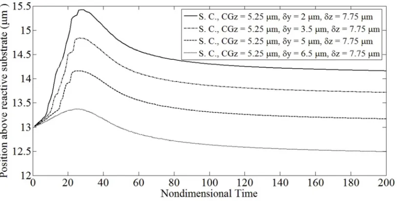
Fig. 5.4: Cell trajectories for binary interactions involving a firmly
adherent spherical, moderately or highly deformed adherent cell and a
spherical free-stream cell for a fixed CGz (13 µm) & fixed δy (2 µm). 59
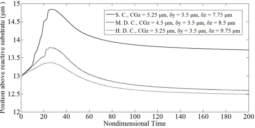
Fig. 5.5: Cell trajectories for binary interactions involving a firmly
adherent spherical, moderately or highly deformed adherent cell and a
spherical free-stream cell for a fixed CGz (13 µm) & fixed δy (3.5 µm). 59
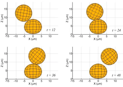
Fig. 5.6: Binary interactions between a firmly adherent, moderately
deformed cell and a spherical free-stream cell (δx = -9 µm, δy = 3.5 µm,
Fig. 5.7: Cell trajectories for binary interactions involving a firmly
adherent moderately deformed cell and a spherical free-stream cell
with increasing glancing offsets. 61
Fig. 5.8: Binary interactions between a firmly adherent, highly deformed
cell and a spherical free-stream cell (δx = -9 µm, δy = 3.5 µm, δz = 7.75 µm,
a = 5 µm,γ& = 100 s-1). 62
Fig. 5.9: Cell trajectories for binary collisions involving a firmly adherent
highly deformed cell and a spherical free-stream cell with increasing
glancing offsets. 63
Fig. 5.10: Collisions involving two firmly adherent, moderately deformed
cells and a spherical free-stream cell (δy = -9 µm, δz = 7.75 µm,
a = 5 µm,γ& = 100 s-1). 65
Fig. 5.11: Cell trajectories for binary interactions involving two firmly
adherent, moderately deformed cells and a spherical free-stream cell for
various glances. 65
Fig. 5.12: Cell trajectories for binary interactions involving two firmly
adherent, highly deformed cells and a spherical free-stream cell for
various glances. 66
Fig. 5.13: Cell trajectories for binary interactions involving a firmly
adherent spherical, moderately or highly deformed adherent cell and a
spherical free-stream cell (CGx = -9 µm, CGy = 10.5 µm, CGz = 7.5 µm,
a = 5 µm,γ& = 100 s-1). 68
Fig. 5.14: Cell trajectories for binary interactions involving a firmly
adherent spherical, moderately or highly deformed adherent cell and a
spherical free-stream cell (CGx = -9 µm, CGy = 10.5 µm, CGz = 6 µm,
a = 5 µm,γ& = 100 s-1). 68
Fig. 5.15: Lateral displacement of cells for binary interactions involving
a firmly adherent spherical, moderately or highly deformed adherent cell
and a spherical free-stream cell (CGx = -9 µm, CGy = 10.5 µm, CGz = 6 µm,
Fig. 5.16: Cell trajectories for binary interactions involving a firmly
adherent spherical, moderately or highly deformed adherent cell and a
spherical free-stream cell (CGx = -9 µm, CGy = 10.5 µm, CGz = 6 µm,
a = 5 µm,γ& = 80 s-1). 71
Fig. 5.17: Cell trajectories for binary interactions involving a firmly
adherent spherical, moderately or highly deformed adherent cell and a
spherical free-stream cell (CGx = -9 µm, CGy = 10.5 µm, CGz = 6 µm,
a = 5 µm,γ& = 120 s-1). 71
Fig. 5.18: Cell trajectories for binary interactions involving a firmly
adherent spherical, moderately or highly deformed adherent cell and a
neutrally buoyant spherical free-stream cell (CGx = -9 µm, CGy = 10.5 µm,
CGz = 6 µm, a = 5 µm,γ& = 100 s-1). 72
Fig. 5.19: Cell trajectories for binary interactions involving a firmly
adherent spherical, moderately or highly deformed adherent cell and a
spherical free-stream cell (CGx = -9 µm, CGy = 15 µm, CGz = 6 µm,
a = 5 µm,γ& = 100 s-1). 73
Fig. 5.20: Cell trajectories for binary interactions involving a firmly adherent
spherical, moderately or highly deformed adherent cell and a spherical
free-stream cell (CGx = -9 µm, CGy = 25 µm, CGz = 6 µm,
a = 5 µm,γ& = 100 s-1). 74
Fig. B-1: Tumbling sequence of a deformable oblate spheroid in the
proximity of a rigid wall (a = 5 µm, η = 1 Pa, ν = 0.33, α = π/2,
κ = 0.5,γ& = 200 s-1). 88
Fig. B-2: Trembling sequence of a deformable oblate spheroid in the
proximity of a rigid wall (a = 5 µm, η = 1 Pa, ν = 0.33, α = π/2,
κ = 0.75,γ& = 200 s-1). 89
Fig. C-1: Binary interactions between a firmly adherent, spherical
cell and a spherical free-stream cell (δx = -9 µm, δy = 2 µm, δz = 7.75 µm,
Fig. C-2: Binary interactions between a firmly adherent, moderately
deformed cell and a spherical free-stream cell (δx = -9 µm, δy = 3.5 µm,
δz = 7.75 µm, a = 5 µm,γ& = 100 s-1). 91
Fig. C-3: Binary interactions between a firmly adherent, highly deformed
cell and a spherical free-stream cell (δx = -9 µm, δy = 3.5 µm, δz = 7.75 µm,
List of Tables
Glossary
*
x, X, X integration variable, source point, image point
( ,x X) ij
G Stokeslet / Kelvinlet
( ,x X)
Σijk associated stress tensor
( ,x X) ij
K double layer
( ,x X)
* ij
K adjoint double layer
p pressure
u displacement vector
v velocity vector
t surface traction
n outward normal
a particle radius / length of semi-major axis (for spheroids)
as contact radius
F,Fo force vector, parameter in repulsive force model
T torque vector, absolute temperature
kb Boltzmann’s constant
kr0, kf0 unstressed off/on rate
r0 reactive compliance
Greek Symbols
µ
viscosity&
γ shear rate
η shear modulus
ν Poisson’s ratio
α initial particle orientation
ε particle-particle separation
κ aspect ratio of spheroid
ω contact angle
1 INTRODUCTON
[image:17.612.144.506.172.404.2]1.1
Immune Response
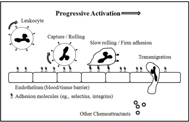
Fig. 1.1 The Leukocyte Adhesion Cascade.
The innate immune response involves the recruitment of white blood cells or leukocytes that
move out of the circulatory system, towards the site of trauma. This process is known as
leukocyte diapedesis and involves several stages including chemoattraction, rolling-adhesion,
tight adhesion and transmigration (Ley et al. (2007)). Upon activation by inflammatory stimuli,
macrophages release cytokines and prompt endothelial cells in the proximity of the infection site
to express selectins. Leukocyte rolling is mediated by P- and E-Selectin (expressed on
endothelial cells) and their corresponding ligands found on the tip of the leukocyte microvilli.
Activated integrins bind tightly to receptors on endothelial cells and further decrease the cell’s
rolling velocity. Eventually, reorganization of the cytoskeleton causes it to spread over
leukocytes to pass through the endothelium and ultimately to the site of trauma (Fig. 1.1). The
process is characterized by a progressive morphological change from a nearly spherical shape to
a flat oblate spheroid. It is believed that deformation of rolling leukocytes enhances rolling
interactions and plays a role in diapedesis (Gee and King (2010)).
Deficiencies in E- and P-Selectin can negate inflammatory response (Kunkel and Ley
(1996)). Moreover, defective integrins impair the ability of leukocytes to stop and undergo
diapedesis resulting in leukocyte adhesion deficiency (LAD) (Kinashi et al. (2004)).
1.2
Mathematical Modeling of Blood Flow
Blood consists of erythrocytes, leukocytes and thrombocytes suspended in viscous plasma. A
milliliter of blood contains approximately 107 white blood cells. As indicated in Figure 1.2, these
cells are composed of a nucleus, granules, cytoplasmic fluid, cytoskeleton, membrane and other
organelles.
The space between the nucleus and cell-membrane is filled with cytoplasmic fluid that
corresponds to nearly half the volume of the cell. While the membrane controls transport into
and out of the cell, the granules play a role in lysis. The exterior surface of the membrane is
covered with undulations (microvilli) which represent folds of excess membrane.
Figure 1.3 is a scanning electron micrograph which clearly illustrates the surface
morphology of the leukocyte microvilli. P-Selectin ligands such as P-selectin glycoprotein
Fig. 1.3 Scanning Electron Micrograph (SEM) of a white blood cell (Courtesy: Dr. Thomas R. Gaborski (SiMPore
Inc.)).
ligand-1 (PSGL-1) and L-Selectin are expressed on the tips of the microvilli and β2 integrin
adhesion molecules such as Lymphocyte function-associated antigen 1 (LFA-1) and
Macrophage-1 antigen (Mac-1) are preferentially located in the folds between successive
microvilli.
A variety of computational techniques have evolved to solve problems involving
immersed objects, following the pioneering work of Fröhlich and Sack (1946). Domain based
methods including volume of fluid and the immersed boundary method (IBM) have been
cell deformation. However, such numerical schemes tend to be computationally expensive, since
they necessitate a complete discretization of the flow domain. Besides, since the flow domain is
confined by the bounding box, free-stream and rolling cell travels are limited. Moreover,
simulations involving multiple cells required approximately 100 hours of CPU time (Jadhav et
al. (2007), Hoskins et al. (2009)). The numerical strategy adopted in this thesis is based on
boundary element techniques (BEM) that are ideal tools to solve problems involving
suspensions. A 3D problem could be solved by surface discretization, since the problem
dimensionality is reduced by one. Multi-particle simulations are thereby not as computationally
intensive as the aforementioned domain based methods. For instance, King and Hammer (2001a)
simulated an array of 14 adherent cells as opposed to 6 cells tested by Pappu et al. (2008), to
estimate stable rolling of leukocytes. Furthermore, the cell travel is not limited by the size of the
flow domain. Our method involves a range completion of the double layer and is known as the
Completed Double Layer Boundary Integral Equation Method (CDL-BIEM) (Phan-Thien and
Fan (1996), Phan-Thien et al. (1992)).
The origins of biological cell modeling can be traced back to the fundamental fluid
dynamics problem of the deformation and dislodging of liquid drops. The complex nature of the
leukocyte structure has generated considerable debate regarding the appropriate constitutive
model. Lim et al. (2006) summarize several constitutive models proposed for living cells and
discuss the advantages and limitations of each model. While Dong et al. (1999) modeled the cell
as a Hookean ring surrounding an incompressible fluid, N’Dri et al. (2003) hypothesized that the
cell could be modeled as a two-dimensional compound liquid drop. These ideas have been
extended to 3D by Jadhav et al. (2005), Pappu and Bagchi (2008) and Pappu et al. (2008) via a
Fig. 1.4 Leukocyte modeled as a linear elastic solid.
The ability of leukocytes to undergo large deformations has also been modeled using
compound viscoelastic drop models proposed by Khismatullin and Truskey (2012). The present
study accounts for cell deformation by approximating the leukocyte as a Hookean solid with
material parameters η, νp (Fig. 1.4). This constitutive material model has been adopted
previously by Wankhede et al. (2006) and suitably represents the small deformations associated
with selectin-mediated rolling.
1.3
Modeling Biochemistry
Leukocyte rolling is characterized by the formation and breakage of receptor-ligand bonds,
thereby making the behavior noisy. A probabilistic model formulated by Bell (1978) has been
frequently employed in prior studies to model adhesive interactions between the cell and the
1.4
Leukocyte Trafficking
The necessity to quantify factors leading to cell trafficking arises from the accumulation of
multiple cells to combat an infection. King and Hammer (2001a,b) described a “hydrodynamic
recruitment” mechanism through which a firmly adherent rigid cell could recruit circulating
cells. This has been supported by experimental evidence in cell-free assays (King et al. (2001))
and measurements of leukocyte capture in vivo using hamster cheek pouch (Lee and King
(2006)). The multi-particle adhesive dynamics simulation was employed by King and Hammer
(2001b) to model this phenomenon.
1.5
Novelties in Proposed Research
The role of contact forces for deformable leukocytes modeled has not been thoroughly
investigated for tethered cells in static equilibrium (Smith et al. (1999)). Besides, Wankhede et
al. (2006) assume a constant, time-independent contact area that arises from the wall reaction.
Moreover, the existing bio-chemistry subroutine computes the number of receptors available for
bond formation based on the proximity of the cell to the reactive substrate. The proposed
formulation supplements this algorithm by including a dynamically evolving interfacial contact
based on the theoretical model formulated by Hertz for an elastic sphere in contact with a rigid
wall (Villaggio (1996)).
Secondary recruitment studies conducted by King and Hammer (2001b) comprise of
spherical adherent or slowly rolling cells interacting with free-stream cells. However, in an
cells at varying stages of the adhesion cascade. The influence of adherent cell deformation on
cell accumulation is thereby accounted for and forms the central theme of this thesis.
Additionally, the integration of the adjoint double layer kernel over the singular element
was achieved by subtracting the contribution of the corresponding integrals over the remaining
elements. In this thesis, this integration is achieved by subtracting the integration of the double
layer kernel over the non-singular elements as proposed by Phan-Thien and Fan (1996).
Moreover, validation of the modified kernel functions for the half-space are investigated through
a series of test cases involving non-spherical deformable inclusions in the proximity of the rigid
substrate.
Unlike previous studies conducted with the multi-particle adhesive dynamics algorithm,
that elucidated the ability of lubrication forces to induce cell deformation, the proposed work
accounts for these short range non-adhesive interactions. From a programming viewpoint, the
source code has been modified to input different meshes within the same simulation. The
accuracy of the numerical scheme that was limited to 2nd order Gaussian quadrature has been
supplemented with the higher order quadrature schemes.
1.6
Statement of Work
“To simulate the deformations of rolling white-blood cells adhering to the endothelium in order
to study effect of deformation on recruitment of WBC’s to sites of injury or infection with a
1.7
Thesis Objectives and Scope
• The probabilistic bond-kinetics algorithm is appropriately modified to account for cell
deformation and its effect is assessed on the rolling velocity of the cell.
• The hydrodynamic recruitment of free-stream leukocytes is investigated using the
steady-state morphologies of deformed, adherent cells.
• The research only accounts for infinitesimal to moderate deformation of the leukocytes.
Non-linear material response is beyond the scope of this thesis.
• Dynamic deformation and mobility simulations have been restricted to solitary cell
rolling studies.
• This thesis addresses secondary recruitment through hydrodynamic interactions between
adherent and free-stream leukocytes. Other modes of secondary recruitment stemming
from binary interactions between free-stream WBCs or L-selectin mediated cell-cell
adhesion are only briefly introduced.
Chapter 2 discusses the theoretical model including the numerical
methodology, its implementation and results from several fundamental test cases. Short-range
adhesive interactions such as electrostatic repulsion and lubrication are reported in Chapter 3. A
formulation for computing the interfacial contact area stemming from cell compression and its
subsequent effects on adhesive interactions is addressed through a series of rolling simulations
for solitary cells of varying sizes and compliances in Chapter 4. Chapter 5 discusses the primary
goal of this thesis: the phenomenon of secondary recruitment of free-stream leukocytes through
2 THEORETICAL MODEL
2.1 Problem Formulation
We use the parallel plate flow chamber to study cell-substrate adhesion. The flow domain is
bounded by two infinite parallel plates (the lower surface of which is functionalized with
adhesion molecules to simulate the inflamed endothelium) and the channel height is much
greater than the radius of the rolling cell. The flow domain is representative of 2D flow and is a
reasonable model for leukocytes in microcirculatory flow. The velocity profile near the surface is
assumed to be linear and the motion of a leukocyte in the proximity of the substrate can be
described as a treading motion for the inclusion in a semi-infinite shear flow, as indicated in
Figure 2.1.
Moreover, the Reynolds number associated with the flow in these experiments is << 1
and the Navier-Stokes equations reduce to Stokes equations.
0
= ⋅
∇ v , −∇ + ∇ =p
µ
2v 0 (2.1)where v, p are velocity and pressure, respectively. No slip boundary conditions are enforced at
the planar interface at all times. Particles immersed in the flow are subjected to stresses arising
out of intercellular collisions, adhesive interactions and fluid shear. For a deformable particle, the
deformation is computed by first determining the traction distribution over the cell surface. Small
displacements in an isotropic, homogenous elastic solid are governed by Navier’s equation,
2
1
1 2−
ν
p∇∇⋅ + ∇ =u u 0 (2.2)where u, νp are displacement and Poisson’s ratio, respectively. The three problems of interest
have been termed mobility (translation and rotation), exterior (surface traction), and interior
(deformation). The following section discusses the formulation of boundary element techniques
employed to solve these three problems.
2.2
Boundary Element Method
A. Mobility Problem
The CDL-BEM is employed to solve the mobility problem of the inclusion. The starting point is
the integral representation of the Stokes equations, derived using the Lorentz reciprocal theorem.
(X)+
∫
( )x Σijk( ,x X) ( )x ( )x =∫
( ,x X)σki( )x ( )x ( )xp p
j k i ij k
S S
where Gij (Oseen-Burger tensor or Stokeslet) is the i-component of velocity due to a point force
acting at X in the j-direction, Σijk(x,X) is the associated stress, S = ⋃Sp, where p = 1,2…M and M
is the number of particles. Here, n represents the outward normal and
σσσσ
is the fluid stress tensor given by( ( ) )
σ= −pI+ ∇ + ∇
µ
v v t (2.4)The integrals on the right and left hand side of Eq. (2.3) are known as the single and
double layer potentials, respectively, in analogy with potential theory. Decoupling the mobility
problem from the traction and displacement problems permits the mobility calculation of the
particle as a rigid body (Phan-Thien and Fan (1996)). The velocity representation using only the
single layer potential results in an ill-conditioned Fredholm integral equation of the first kind.
This problem is circumvented by dropping the single layer term and expressing the velocity
integral as a Fredholm integral equation of the second kind with an unknown surface density φ,
( )ξ =ϕj( )ξ +
∫
( , )x ξ ϕi( )x ( )xp
j ij
S
v K dS , ξ∈S p (2.5)
where Kij is the double layer kernel and is given by,
Kij( , )x ξ =2nk( )x Σijk( , )x ξ (2.6)
A factor of two is included in the above expression in order to achieve a spectral radius of
unity. The eigenvalues Γ of the double-layer are real such that |Γ| ≤ 1 (Phan-Thien and Tullock
(1993)). For Γ = -1, there are six null solutions to the double layer kernel, each corresponding to
a rigid body mode of the particle. Thereby, for every particle one needs to impose six linearly
recognized this and sought to complete the double-layer representation by using velocity fields
of point forces and torques and associated them with the null solutions on the particle surface
( )
,
=
p p,l
l
F ϕϕϕϕ ϕϕϕϕ (2.7)
( )
,
+
=
p p,l 3 l
T ϕϕϕϕ ϕϕϕϕ (2.8)
where (l=1,2,3) represents translation, ((l+3)=4,5,6) represents rotation of particle p, and ⋅ ⋅,
denotes the natural inner product
( ) ( )
, =δ δ
p,i q, j
pq ij
ϕ ϕ
ϕϕ ϕϕ
ϕ ϕ (2.9)
The null solutions are normalized with respect to the inner product and are given by
(p,l) = el p S ϕϕϕϕ (2.10) ( ) e + = × p,l 3 l l 1 I
ϕ
ρ
ϕ
ϕ
ρ
ρ
ϕ
ρ
(2.11)where
{ }
el are the unit vectors along the xldirections,ρ= −ξ x (p)c is the position vector from the
center of Sp to a point ξ on the surface (i.e.,ξ∈S ) and Ip l are the normalized constraints
expressed as
2 2
2 3
(
ρ
ρ
)=
∫
+p
1 S
I dS (2.12)
2 2
3 1
(
ρ
ρ
)=
∫
+p
2 S
I dS (2.13)
dS I
S
3 ( )
2 2 2
1
ρ
ρ
+Equations (2.10)-(2.14) are applicable to spherical inclusions. A Gram-Schmidt
orthonormalization technique is essential for non-spherical inclusions; previously incorporated in
the formulation by Mody and King (2005) to simulate the mobility of oblate spheroids. The
aforementioned procedure that maps the eigenvalue of -1 to zero without affecting the rest of the
spectrum is known as the Wielandt’s deflation scheme and will be employed in the exterior and
interior problems as well. In order to ensure that the problem could be solved iteratively, the
eigenvalue of +1 is also deflated by introducing orthonormalized eigenvectors ψp, of the adjoint
K* such that
( )
p = n
p ξ
S
ψ ψψ
ψ , ξ∈Sp (2.15)
The final integral expression is given by
( ) ( ) ( ) ( ) ( ) ( )
j j
1
( ) ( , ) ( ) ( ) ( ) , ( ) , ( ) ( ) ,
2
j ξ x ξ i x x ξ ξ j ξ ξ b
ϕ +
∫
ϕ +ϕ −ψ = − ψp
p,l p,l p p p p
ij j
S
K dS ϕϕϕϕ ϕϕϕϕ ψψψψ ϕϕϕϕ b ψψψψ
where
1
1
( ) ( ) ( ( ) ) ( , )
2 i
ξ ∞ ξ ξ x
=
= − +
∑
M (p)− (p)×∇ pj j i i ji c
p
b v F T G (2.16)
Once φ is computed, the velocity is determined using the following expression
( ) ( )
( )ξ = −ϕ p,l ( )ξ p,l ,
j j
v ϕϕϕϕ ϕϕϕϕ (2.17)
The Stokeslet must be supplemented with image and extra terms in order to account for
the half space (Fig. 2.2) (Tran-Cong and Phan-Thien (1986), Phan-Thien et al. (1992));
(Appendix A). This method of reflections (Ainley et al. (2008), Blake (1971), Blake and Chwang
B. Exterior Problem
The traction based Completed Adjoint Double Layer Boundary Element Method (CADL-BEM)
(Phan-Thien and Fan (1995)) is adopted for the traction distribution on the cell surface. The
single layer representation of the velocity field is:
(X)= ∞−
∫
( ,x X) ( )x ( )xp
j j ij i
S
v v G t dS (2.18)
Fig. 2.2 Method of reflections to satisfy boundary conditions of no-slip and no-displacement boundary conditions at
rigid substrate.
The traction at domain point X, with unit normal nk(X), generated by the velocity field is
2 (X)=2 (∞ X)−
∫
∗( , ) ( )x ξ x ( )xp
j j ij i
S
where t∞j is the ambient traction and Kij∗ is the associated traction of Gij, also known as the
adjoint double layer kernel.
) , ( ) ( 2 ) ,
(x X =− X Σjik x X
∗
k
ij n
K (2.20)
Phan-Thien and Tullock (1993) and Phan-Thien and Kim (1994) discuss the spectral properties
of the double layer and its adjoint in depth. When the domain point approaches the particle
surface, the adjoint double layer suffers a jump discontinuity equivalent to –tj. Hence, (2.19) can
be re-arranged to give
( )ξ +
∫
∗( , ) ( )x ξ x ( )x =2 ( )∞ ξ pj ij i j
S
t K t dS t , ξ∈S p (2.21)
The spectral radius of the adjoint double layer is equal to unity. The eigenvalue Γ = -1 is
associated with six eigenfunctions representing the rigid body motions of the particle (as
discussed in the previous section). In order to generate a unique solution, six independent
constraints in the form of forces and torques are specified on the particles. For spherical
inclusions, 3 3 ( ) ( ) 1 1 1 1 , t = = = ⋅ =
∑
∑
∫
pp,l p,l (p)
l l
l p l s p
e e tdS F
S S
ϕ
ϕ
ϕ
ϕ
ϕ
ϕ
ϕ
ϕ
(2.22)( )
3 3
( ) ( ) ( )
1 1
( )
, t δ t
ϕ ε ε + + = = = × ⋅ =
∑
∑
∫
p pp,l 3 p,l 3 il k p
j ijk (p) l
l l l S
(p) p l jlk (p) k
l
r
e r dS
I T r I ϕϕϕϕ (2.23)
For non-spherical inclusions, the RHS of Eqs. (2.22-23) are linear combinations of the external
Equations (2.22) and (2.23) are linearly combined with Eq. (2.21) to give the final
boundary integral equation for the traction problem:
( ) ( )
( )ξ +
∫
∗( , ) ( )xξ
x ( )x +∑
( )ξ ,t = ( )ξp
p,l p,l
j ij i j
p,l S
t K t dS
ϕ
ϕ
ϕ
ϕ
ϕ
ϕ
ϕ
ϕ
b (2.24)where
( )
1
( )ξ 2 ∞ ε
= + +
∑
(p) l(p) pj j jlk (p) k
p p l
T
b t F r
S I (2.25)
Unlike for the double layer, the Wielandt deflation scheme is employed to map only the
eigenvalue of -1 to zero. As reported by Phan-Thien and Fan (1996), the deflation of the
eigenvalue of +1 is not necessary for the exterior problem.
C. Interior Problem
Cell rolling deformations at low to intermediate stresses (≤ 5 dyne/cm2) are relatively small and
can be approximated by a linear elastic model. Evans et al. (2005)showed that for compressive
deformations of the order of hundreds of nanometers, neutrophil response is well approximated as
a Hookean solid. Using Betti’s reciprocal theorem, the integral equation for the displacement u is
given by
( )ξ = −
∫
( , ) ( )x ξ x ( )x +∫
2 ( , )x ξσ
ki( )x ( )x ( )xp p
j ij i ij k
S S
u K u dS G n dS (2.26)
where each particle is assumed to be Lyapunov smooth (i.e., having well-defined unit normal
vector). Gij(x,ξ) gives the i-component of displacement due to a point force acting at ξ in the
j-direction and is known as the Kelvinlet. Since the spectral radius of the elastic double layer is
vector and r = x – x(p) is the position vector from the particle center x(p)). The corresponding
orthonormalized eigenfunctions for a sphere are
(p,k) = ek p
S
ϕϕϕϕ (k = 1, 2, 3) (2.27)
( )
r e
+ = ×
p,k 3 p
k p k 1 I
ϕϕϕϕ
(2.28) where 2 ( ) r r =∫
⋅ − pp p p p
k k
S
I r dS (2.29)
The six linearly independent constraints imposed on the solution are of the form
( )
,u =0 p,l
ϕϕϕϕ l=1,2…6 (2.30)
and are linearly combined with Eq. (2.26) to give the final integral expression,
( ) ( )
( )ξ +
∫
( , ) ( )x ξ x ( )x +∑
( )ξ ,u =∫
2 ( , )x ξσ
ki( )x ( )x ( )xp p
p,l p,l
j ij i ij k
p,l
S S
u K u dS
ϕ
ϕ
ϕ
ϕ
ϕ
ϕ
ϕ
ϕ
G n dS (2.31)The traction solution from the exterior problem serves as an input to the right hand side of Eq.
(2.31), using which the displacement is solved for iteratively. The Wielandt deflation maps the
eigenvalue of -1 to zero, while retaining the rest of the spectrum. Moreover, unlike the mobility
problem, deflation of the eigenvalue of +1 is not necessary for the interior problem (Phan-Thien
2.3
Numerical Validation
The validity of the BEM formulation was determined through a series of simulations involving
the translation and rotation of deformable spherical and spheroid inclusions in the proximity of
the substrate. The surfaces of the particles are discretized using QUAD9 Lagrangian elements
(Fig. 2.3).
Fig. 2.3 QUAD9 Lagrangian element.
Super-parametric elements are employed where the unknown is assumed piece-wise
constant. Numerical integration is performed using up to 3x3 Gaussian quadrature. The six faces
of a cube are subdivided into 96 elements and projected onto the surface of a sphere (Fig. 2.4a).
The sphere maybe compressed along an axis to generate oblate spheroids of several aspect ratios
(Fig. 2.4b). The shear modulus η ranges from 0.5 – 23 Pa (Rosenbluth et al. (2006)), while a
constant Poisson’s ratio of 0.33 is maintained in all simulations. The positions of all the material
double precision FORTRAN 95 and the output files post-processed in MATLAB. A maximum of
1000 iterations for solution convergence per unit time step is adopted with the tolerance being set
at 10-4. All simulations are performed on Sun X4600M2 servers with 2.3GHz AMD Quad Core
processors at a time step size of 10-4 for a period of 1 s.
(a) (b)
Fig. 2.4 96 element discretization of (a) sphere (b) oblate spheroid.
A. EFFECT OF SUBSTRATE ON PARTICLE TRAJECTORIES
In a zero gravity field, micro-spheres almost move parallel to the wall without crossing the
streamlines (Bretherton (1962), Goldman et al. (1967a,b)). Vis-à-vis, dense inclusions are found
to sediment or drift towards the wall (Decuzzi and Ferrari (2006)). On the other hand
non-spherical particles such as spheroids exhibit a more complicated behavior. The Stokes number of a
particle St is expressed in terms of the Reynolds number Re, particle density ρg and density of the
surrounding medium ρ as follows:
ρ
ρ
= g
St Re (2.32)
discussed in this section Re, St << 1 and the particle follows a periodic motion predicted
analytically by Jeffery (1922). The variation in the centroidal position of the particle is plotted
with respect to nondimensional time t that is defined as follows:
t = Simulation running time (s) / {Time step (s) x Frequency of data save}
Therefore for a running time of 1 s, a step size of 10-4 s and data saved every 10 time steps, the
non-dimensional time is 1000. The same definition is adopted for all simulations described in
current and subsequent chapters.
The trajectories of a neutrally buoyant and dense deformable spherical inclusion at shear
rates of 100 and 200 s-1 are indicated in Figure 2.5. As can be seen, in the absence of gravity, the
Fig. 2.5 Comparison between the trajectories of a buoyant and dense spherical inclusion
(a = 5 µm,η = 1 Pa, ν = 0.33,γ& = 100, 200 s-1).
inclusion appears to move almost parallel to the wall. On the other hand, dense inclusions drift
towards the wall. Moreover, doubling the shear rate moderately alters the trajectories since the Re
and St numbers only marginally increase. The particle trajectories for oblate spheroids with aspect
Fig. 2.6 Comparison between the trajectories of a buoyant and dense oblate
spheroid inclusion (a = 5 µm,η = 1 Pa, ν = 0.33, α = π/2, κ = 0.75,γ& = 100 s-1).
Fig. 2.7 Comparison between the trajectories of a buoyant and dense oblate
spheroid inclusion (a = 5 µm,η = 1 Pa, ν = 0.33, α = π/2, κ = 0.5,γ& = 100 s-1).
The analytical expression for the time period τ for the Jeffrey’s orbit of a spheroid inclusion with
aspect ratio κ in an unbounded shear flow (shear rateγ&) is given by
(
1)
2π
τ κ κ
γ −
= +
For an oblate spheroid with κ = 0.75, τ ~ 13/γ& and for κ = 0.5, τ ~ 16/γ&. The numerical values for
these time periods are τ ~ 15/γ& for κ = 0.75 (Fig. 2.6), τ ~ 19/γ& for κ = 0.5 (Fig. 2.7) and
represent a modified Jeffrey’s orbit in a wall bounded shear flow (Mody and King (2005)). Figure
2.8 indicates that by doubling the shear rate, this time period is halved. The results for the
mobility of both spherical and spheroid inclusions appear to be in good agreement with those
reported by Lee et al. (2009).
Fig. 2.8 Comparison between the trajectories of a buoyant and dense oblate
spheroid inclusion (a = 5 µm,η = 1 Pa, ν = 0.33, α = π/2, κ = 0.5,γ& = 100, 200 s-1).
B. SHAPE DYNAMICS
A deformable spherical inclusion placed in a linear shear flow deforms into an ellipsoidal shape
(Fig. 2.9) in a manner similar to the shearing of a square block into a rhomboidal shape.
Moreover, the aspect of ratio of the deformed profile is governed by the compliance of the
material and the fluid shear rate. Steady state profiles for inclusions of varying shear moduli at
Fig. 2.9 Deformed shape of a spherical inclusion in a shear flow.
Fig. 2.10 Steady state shapes of a deformable spherical inclusion in the proximity of a rigid wall. For both
In Figure 2.10a-b, the shear modulus of the cell is relatively small compared to the fluid
shear stresses and the sphere deforms into an ellipsoid. On the other hand, in Figure 2.10c-d, the
shear modulus of the cell is much higher in comparison to the fluid shear stress. The inclusion
thereby retains its spherical profile. The deformed shapes predicted here are in good agreement
with those reported for Neo-hookean solids (Gao and Hu (2009)) and elastic capsules (Pozrikidis
(1995)). Besides, the steady state shapes remain unchanged throughout the simulation (Fig. 2.11).
Fig. 2.11 Tank treading sequence of a deformable spherical inclusion in the proximity of a rigid wall
(a = 5 µm,η = 1 Pa, ν = 0.33,γ& = 100 s-1).
The particle exhibits a ‘tank-treading’ motion in which the particle appears to tumble in place and
the inability of the major-axis of the deformed profile to complete a full revolution comprising of
2π radians with the minor axis taking its place in every cycle.
Fig. 2.12 Advection of material points along the perimeter of an ellipse.
The deformation of deformable, initially spheroid particles are similar in nature to their
spherical counterparts, with the exception that the shape dynamics depends on the aspect ratio of
these inclusions. Unlike spherical inclusions, a steady state shape is never achieved (Gao et al.
(2012)). The ratio of the hydrodynamic to the elastic forces is expressed in terms of a
dimensionless number known as the viscous number Vi.
µγ η
= &
Vi (2.34)
Based on the dimensions of the spheroid prior to insertion into the shear flow and the viscous
number, two forms of shape oscillations are observed – tumbling and trembling. The competition
between the hydrodynamic shearing forces to deform the material lying along the maximum
stretch axis (α = π/4) and the elastic forces to restore the deformation generates a condition where
the long axis in the deformed configuration does not always remain as the reference axis. When
preserve the shape, the inclusion is said to “tumble.” On the other hand, when the shearing forces
are comparable in magnitude to the elastic forces, the particle shape deviates from its original
configuration and is considered to “tremble.” This mode has been observed experimentally by
Kantsler and Steinberg (2006) and is synonymous to the breathing mode identified by Misbah
(2006) or the swinging mode described by Noguchi and Gompper (2007).
Fig. 2.13 Tumbling sequence of a deformable oblate spheroid in the proximity of a rigid wall
(a = 5 µm,η = 1 Pa, ν = 0.33, α = π/2, κ = 0.5,γ& = 100 s-1).
In the “tumbling” mode, the major axis makes a complete revolution as observed in Figure
tumbling is associated with a periodic flipping of the particle in the shear plane (Lebedev et al.
(2007)). On the other hand, in the “trembling” mode, the long axis never completes a full
revolution with the minor axis taking its place prior to the completion of 2π radians. In Figure
2.14, for non-dimensional time t = 750, for the oblate spheroid whose initial aspect ratio was 0.75,
the deformed configuration is nearly spherical, thereby indicating that a “tumbling” mode
transitions into a “trembling” mode with an increasing aspect ratio.
Fig. 2.14 Tumbling sequence of a deformable oblate spheroid in the proximity of a rigid wall
(a = 5 µm,η = 1 Pa, ν = 0.33, α = π/2, κ = 0.75,γ& = 100 s-1).
At a viscous number of 0.1, the present study predicts the transition to occur at an aspect
lower aspect ratio (between 0.5 and 0.75), implying that the strength of the hydrodynamic forces
equally influenced the trembling or tumbling modes (Appendix B).
A similar observation was made by Gao et al. (2012) for ellipsoidal inclusions that were
modeled as a Neo-Hookean solids. For a viscous number of 0.2, the transition from the tumbling
to the trembling regime was reported to occur at an aspect ratio of 0.681. Moreover, the
stress-strain relation for Neo-Hookean materials can be expressed in terms of the principal stretch ratio λ
as follows
2
1
σ λ
λ
= −
E (2.34)
where λ = ε +1, ε is the infinitesimal strain. For ε <<1, the term λ2 ~ 1. Thus Eq. (2.34) reduces to
σ =E ε (2.35)
Equation (2.35) represents Hooke’s Law of linear elasticity for infinitesimal deformations.
Although the non-linear hyperelastic model potentially predicts larger deformations during the
alternate stretching and compression of the material points, the transition from tumbling to
trembling as predicted by the linear elastic model is in good agreement with that predicted for
finite strain models at low hydrodynamic shear forces.
The computational scheme based on boundary element methods presented here is
employed in all the simulations in forthcoming chapters including short-range non-adhesive
interactions between free-stream cells, adhesive interactions for solitary cells and hydrodynamic
interactions between free-stream and firmly adherent cells. Oblate spheroid shapes have been
specifically simulated in order to assess the accuracy of the Gram-Schmidt orthonormalization
simulations comprising of spherical cells, this orthonormalization would be crucial to deformed
cells, whose profiles deviate from a spherical morphology.
3 SHORT RANGE NON-ADHESIVE INTERACTIONS
Collisions between neighboring cells are unavoidable in mathematical modeling of dense
suspensions of blood cells. Such collisions could potentially lead to membrane overlap of the
interacting cells. However, in an actual physiological scenario, cells do not overlap or pass
through the reactive substrate during adhesive interactions. Moreover, the presence of asymptotic
short-range forces prevents such interferences. While some of these forces arise from the electric
potential associated with the cells, others prevail due to the pressure buildup stemming from the
shearing or squeezing of the surrounding viscous plasma. The inclusion of Van Der-Waal’s and
lubrication forces is to primarily prevent cells from overlapping with each other and interfering
with the substrate.
3.1 Van Der-Waal’s Interactions
At cell membrane separations of 50 - 250 Å, electrostatic repulsive forces prevail since the net
charge on both cells has the same sign. The magnitude of this force is expressed as
1
τε τε
τ − −
= −
o rep
F e F
e (3.1)
where 1/τ – length scale and ε – surface-to-surface separation distance. For cell-cell interactions,
Frep is directed along the line joining the centers of the two particles and induces perturbations in
the translation of the interacting particles. For cell-substrate interactions, this force is directed
normal to the substrate. The value of τ is set at 2000 µm-1, while Fo varies between 106 - 109 pN.
In order to simplify the modeling, these forces are assumed to not produce any deformation in
The presence of microvilli on the surface of the cell and a steric layer on the wall is
modeled as a uniform roughness indicated by es and ew, respectively (Fig. 1.4). The values for
these two parameters were set to 175 and 50 nm, respectively. Both adhesive and non-adhesive
interactions occur at the tips of these roughness elements. Moreover, since the dimensions of
these elements are much smaller in comparison with the dimensions of the cell, their effect on
the flow-field is neglected.
3.2 Lubricated Collisions
A thin film of plasma separates interacting cells that are in close contact to one another (Goddard
(1977)) and the Poisseulle theory of elastohydrodynamic lubrication is applicable to the current
study where deformations are considered to be infinitesimal. The theoretical background for
cell-cell lubrication is based on the works of Nasseri et al. (2000) and Rognon and Gay (2009). The
ability of a cell to deform is expressed in terms of the dimensionless elasticity number∈ given by
1.5 0 2.5 0 4θµ ∈= ε u a (3.2)
where u - initial velocity,0 ε0- initial separation,
2 1 ν θ π − =
E , E-Young’s modulus, a-particle radius
and µ-viscosity of medium. For leukocytes,∈typically ranges between 10-6 - 10-2 (Chang and
Wang (1998)), indicating that the cells are reasonably compliant. Although the Poiseulle theory
of lubrication is synonymous with small deformation theory, the same has been introduced to
highlight its influence on modulating the intercellular contact area.
For pairwise interactions, the force inducing deformation Felas is expressed as a sum of
lubr shear
elas F F
F = + (3.3)
The lubrication theory has been strictly applied to the deformation of spherical cells with
identical radii and its effect on particle mobilities has been excluded. Moreover, this study adopts
a minimum film thickness and assumes that the film is stable with negligible variations in
film-thickness arising from cell deformation. For two equal sized spherical cells ‘A’ and ‘B’ moving
relative to one another in a viscous medium, the force exerted by particle ‘B’ on ‘A’ is given by,
sq lubrAB sh
lubrAB
lubr F F
F = + (3.4)
where the subscripts sh and sq indicate shearing and squeezing, respectively (Nasseri et al.
(2000)). A unit vector lAB is introduced to define the line joining the centers of particles A and B.
Additionally, vectors pAB and qAB are defined as follows
p = ⋅ i+ ⋅ j− + k
+ +
x z y z
x 2 y 2
AB AB AB AB
AB x 2 y 2 x 2 y 2 AB AB
AB AB AB AB
l l l l
l l
l l l l
(3.5)
q = − i+ j
+ +
y x
AB AB
AB x 2 y 2 x 2 y 2
AB AB AB AB
l l
l l l l
(3.6)
where superscripts x, y, z represent global Cartesian co-ordinate system and i, j, k are unit vectors
in the respective directions. The squeezing and shearing components are given as
B l l uAB AB A
sq lubrAB
a
F = ⋅
ε πµ
2
3 2
(3.7)
(
p p B q q B)
uAB AB A AB A sh
lubrAB
a a
F ⋅ +
= ε
where uAB = uA -uB is the relative velocity of cell ‘A’ with respect to ‘B’. Note that the squeeze
component arises due to the cells approaching each other, while the shear component is
generated by the cells moving past one another. The right hand side of Eq. (2.25) is suitably
augmented as per the traction on local elements to compute a converged traction distribution on
the cell surface.
3.3 Numerical Validation
The numerical code has been appropriately modified to account for non-adhesive interactions.
An adaptive time step of 10-4 - 10-5 is employed based on the proximity of the colliding cells.
The integration of the double layer and the adjoint double layer over the singular element is
carried out as per the strategy proposed by Phan-Thien and Fan (1996) with the exception that
the adaptive discretization of the singular elements has not been included in this thesis.
The combined effect of colloidal and lubrication forces are illustrated through numerical
simulations for equal sized cells with a = 5 µm, η = 8 kPa, ν = 0.33 for the first case and a = 5
µm, η = 4 kPa, ν = 0.33 for the second case. Figure 3.1 indicates the lubrication gap for the two
cases at the same time instant. Figure 3.1b indicates a larger lubrication gap stemming from the
compressive deformation of the more compliant cells (η = 4 kPa). The deformed profiles have a
distinct parabolic profile (Fig. 3.2) (Davis et al. (1986)) and the consequence of the deformation
is an increased intercellular contact area. Similar cases involving elastic capsules (Jadhav et al.
(a) (b)
Fig. 3.1 Lubricated collisions between two spherical cells in the proximity of the reactive substrate. For both
simulations a = 5 µm,γ& = 100 s-1, ν = 0.33: (a) stiff particles, η = 8 kPa (b) relatively more compliant particles, η = 4
kPa.
Fig. 3.2 Lubricated collisions between elastic spheres.
Such deformations between colliding neutrophils have been observed in vitro by Kadash
et al. (2004) in order to understand the influence of the inter-cellular contact area on the shear
thresholding of leukocytes. The asymptotic variations in the shear and squeeze components with
Fig. 3.3 Variation in shear (□) and squeeze components (◊) of lubrication with increasing cell-cell separation.
Fig. 3.4 Trajectories of free-stream cells undergoing binary collisions in the proximity of the reactive substrate.
Owing to its position above the wall, the upper cell experiences a lower resistance and
translates at a higher velocity as compared to its lower counterpart. Eventually, upon catching up
with the lower cell, the short-range repulsive forces push the cells apart and the lower cell is
cells towards a reactive substrate via binary collisions has been demonstrated previously (Melder
et al. (1995, 2000)).Electrostatic repulsion forces introduced in this chapter are also employed in
simulations involving single cell rolling as this prevents membrane substrate overlap. Moreover,
the presence of lubrication forces between colliding cells is also acknowledged through the
4 ADHESIVE INTERACTIONS