1300 nm optically pumped quantum dot spin vertical external-cavity surface-emitting
laser
S. S. Alharthi, J. Orchard, E. Clarke, I. D. Henning, and M. J. Adams
Citation: Applied Physics Letters 107, 151109 (2015); doi: 10.1063/1.4933334
View online: http://dx.doi.org/10.1063/1.4933334
View Table of Contents: http://scitation.aip.org/content/aip/journal/apl/107/15?ver=pdfcov
Published by the AIP Publishing
Articles you may be interested in
Control of emitted light polarization in a 1310 nm dilute nitride spin-vertical cavity surface emitting laser subject to circularly polarized optical injection
Appl. Phys. Lett. 105, 181106 (2014); 10.1063/1.4901192
Controlled switching of ultrafast circular polarization oscillations in spin-polarized vertical-cavity surface-emitting lasers
Appl. Phys. Lett. 104, 022409 (2014); 10.1063/1.4862330
High power 1.25 μ m InAs quantum dot vertical external-cavity surface-emitting laser J. Vac. Sci. Technol. B 29, 03C113 (2011); 10.1116/1.3555379
Linearly polarized dual-wavelength vertical-external-cavity surface-emitting laser Appl. Phys. Lett. 90, 181124 (2007); 10.1063/1.2735554
Effect of the properties of an intracavity heat spreader on second harmonic generation in vertical-external-cavity surface-emitting laser
1300 nm optically pumped quantum dot spin vertical external-cavity
surface-emitting laser
S. S.Alharthi,1,a)J.Orchard,2E.Clarke,3I. D.Henning,1and M. J.Adams1 1
School of Computer Science and Electronic Engineering, University of Essex, Wivenhoe Park, Colchester CO4 3SQ, United Kingdom
2
Department of Physics and Astronomy, University of Sheffield, Hounsfield Road, Sheffield S3 7RH, United Kingdom
3
EPSRC National Centre for III-V Technologies, University of Sheffield, Mappin Street, S1 3JD Sheffield, United Kingdom
(Received 15 August 2015; accepted 6 October 2015; published online 15 October 2015)
We report a room temperature optically pumped Quantum Dot-based Spin-Vertical-External-Cavity Surface-Emitting laser (QD Spin-VECSEL) operating at the telecom wavelength of 1.3lm. The active medium was composed of 53 QD layers; each threefold group was positioned at an anti-node of the standing wave of the optical field. Circularly polarized lasing in the QD-VECSEL under Continuous-Wave optical pumping has been realized with a threshold pump power of 11 mW. We further demonstrate at room temperature control of the QD-VECSEL output polarization ellipticity via the pump polarization.VC 2015 AIP Publishing LLC. [http://dx.doi.org/10.1063/1.4933334]
Current information processing and computation as well as communication technologies rely solely on the carrier’s charge in semiconductor materials. Recently, a new rapidly growing research field, called spintronics, has been triggered by the first proposal of the so-called spin transistor by Datta and Das in 1990.1Spintronics aims to exploit the concept of using the carrier spin in semiconductor materials to encode information. This concept would lead to producing novel devices with new unique functionalities and improved device performance in comparison to their conventional counter-parts.2–4 Thus, practically successful spintronics will open the door for spin-based quantum information technologies based on this concept.5–7
Spin optoelectronics as a branch of spintronics in partic-ular, has been a subject of very active research in order to de-velop spin-polarized light sources such as spin-polarized light emitting diodes (spin-LEDs) and spin-polarized lasers (spin-lasers).8,9 In spin-polarized devices, unequal spin-up and spin-down carrier populations are generated by either circularly polarized photoexcitation or electrical spin current injection into the active region. This results in an emission with one preferred polarization, either Right (RCP) or Left (LCP) Circularly Polarized, since population inversion only occurs in one spin state. In other words, circularly polarized output can be generated by converting the angular momen-tum information of the spin of carriers to the emitted pho-tons. This occurs according to the optical quantum selection rules where the total spin angular momentum of carriers has to be equal to the angular momentum of the photons.
Spin-LEDs have already been demonstrated with electri-cal spin injection via magnetic contacts.10–12Moreover, spin injection efficiency up to 32% at room temperature has been demonstrated in LEDs using a tunnel injector with a 5T mag-netic field.13From a practical point of view, spin-LEDs are more attractive for applications if they operate at room tem-perature and preferably without the need for large external
magnetic fields. On the other hand, spin-polarized lasers are expected to offer a number of advantages over their spin-LED counterparts. In particular, because of their cavity and active region configuration, vertical cavity surface emitting lasers (VCSELs) have modal, polarization, and dynamic properties that do not exist in LEDs and are significantly dif-ferent from those in edge-emitting lasers.14 Since the afore-mentioned optical selection rule is only valid for device geometries where light emission is perpendicular to the plane of the active region (and the substrate on which it was grown),15,16it follows that vertical cavity devices (VCSELs and VECSELs) are the most suitable candidates for spin-polarized lasers.
Spin VCSELs offer a number of advantages including, among those already mentioned, control of the output polariza-tion17–20and chirp21,22as well as increased modulation band-width.23–26 Threshold reduction is also one of the first predicted and observed characteristics of spin-VCSELs.23,27–29 Furthermore, these lasers provide ultrafast dynamics30 and enhanced emission intensities.31,32 The attributes of spin-VCSELs offer the potential for new applications such as recon-figurable optical interconnects, spin-dependent switches for optical telecommunications, quantum information processing and data storage, quantum computing, bandwidth enhance-ment, high speed modulators, cryptography of optical commu-nication, circular dichroism spectroscopy, biological structure studies, biomedical sensing, and advanced optical devices.8,15
Spin-polarized VCSELs have previously been demon-strated at short wavelengths either electrically driven via spin-polarized current into quantum dot (QD)29,32,33 and quantum well (QW)34,35 active regions or optically by opti-cally pumping a QW18,20,27,28,36,37or bulk17VCSEL. In con-trast, at telecoms wavelengths, we are only aware of one recent report of a 1300 nm optically pumped QW spin-VCSEL at room temperature.20 Herein, we demonstrate a QD-based spin-Vertical-External-Cavity Surface-Emitting Laser (spin-VECSEL) emitting at 1300 nm and operating at room temperature under continuous wave (CW) optical
a)
pumping. An optically pumped QW spin-VECSEL has been demonstrated very recently at the shorter wavelength of 980 nm using a very complicated external cavity configura-tion in order to compensate for the residual linear birefrin-gence in the structure.38In the present contribution, we use a different approach for the external cavity design by employ-ing a high reflection (HR)-coated fiber as the top mirror, sim-ilar to the cavity configuration reported in Refs.39–42. The use of an external cavity configuration introduces distinctive characteristics, as detailed in Ref.43, and with the inclusion of QD gain materials which contribute their own attractive merits such as high gain, low operating threshold and broad gain bandwidth,44,45 this promises to offer further enhance-ments in performance and functionality.
The design of a VECSEL, also known as a semiconduc-tor disk laser, usually comprises a half-cavity VCSEL which includes an active medium formed on top of a Distributed Bragg Reflector (DBR) having a very high reflectivity near the emission wavelength. The external cavity is formed by the addition of one or more dielectric mirrors as required, and the gain medium is usually driven optically by another pump laser. For clarity, in the following, we refer to the grown structure as a half-cavity VCSEL and when coupled with the external reflector a VECSEL. The semiconductor structure of the device used in this work comprises of a mon-olithic QD active region with a DBR. Both were grown on a semi-insulating GaAs substrate by molecular beam epitaxy. The half-cavity VCSEL consists of 25 pairs of AlAs/GaAs forming the bottom DBR stack with a reflectivity above 99.9% for operation at 1290 nm. The majority of the active region is GaAs, and it consists of 15 InAs/In0.12Ga0.88As
dot-in-a-well (DWELL)-capped layers arranged in groups of 3 placed approximately at the antinodes of the intracavity standing-wave of the electrical field for increased optical gain. Each InGaAs capping layer is only 6 nm thick. The InAs QD density in the active region, measured by atomic force microscopy, for an uncapped QD layer grown under similar conditions as the layers in the half-cavity sample was
41010cm2. A similar structure has been reported in Ref.46, but the one used here has 2 extra groups of DWELL layers.
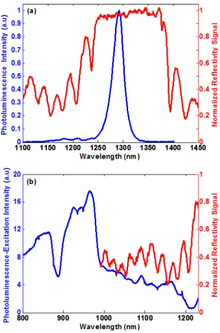
Figure 1(a) shows the room temperature, normal inci-dence photoluminescence (PL) and normalized reflectivity signal obtained from the half-cavity VCSEL using an Accent PL mapping system. The PL peak wavelength and lineshape is determined by the cavity resonance but reference samples with QDs grown under the same conditions without an underlying DBR also show a ground state PL peak at 1290 nm.
Figure 1(b) shows a room temperature PL-excitation
(PLE) spectrum obtained from the half-cavity sample. The spectrum was obtained using quasi-monochromatic excitation from a 150 W tungsten halogen lamp dispersed by a mono-chromator with the detection wavelength set to the peak of the quantum dot ground state PL emission at 1290 nm. Peaks at 900–1000 nm are attributed to absorption in the wetting layer/InGaAs cap, and most of the features>1000 nm corre-spond to peaks in the reflectivity of the DBR, as also shown in Figure 1(b). The increased intensity from wetting layer/ InGaAs cap peaks compared to dot peaks is due to the
increased absorption in the 2D states. The peak due to GaAs absorption at the short wavelength side has a lower energy, and this might be due to cavity effects or reduced excitation power at these wavelengths. The PLE spectrum demonstrates that optical pumping of the half-cavity VCSEL structure at 980 nm is likely to be resonant with the wetting layer/InGaAs cap states. It should be noted that the measured PL/PLE is spin-independent since they were measured on a different ex-perimental set-up without polarization optics in order to determine what part of the structure would be pumped by the 980 nm pump laser in the laser set-up.
The external microcavity of the QD spin-VECSEL was formed by bringing an HR-coated optical fiber, acting as the top mirror (see the inset in Fig.2), in close proximity (lm) to the sample using a piezo-electric translation stage. The mode field diameter of the HR-coated fiber is typically
6lm with reflectivity of 99.8% at 1300 nm and nominally anti-reflective 0.3% at the pump wavelength of 980 nm.
The experimental setup used to achieve the 1300 nm optically pumped QD spin-VECSEL is shown in Fig.2. The QD half-VCSEL sample was pasted on a silicon wafer and held on a customized temperature-controlled copper mount which was maintained at room temperature (293 K). The mounting bracket was attached to one side of a 3-axes piezo-electric translation stage. The sample was optically pumped at the long-wavelength side of the peak of Fig. 1(b)(which is attributed to the absorption in the InGaAs cap) by a
FIG. 1. (a) Room temperature PL and reflectivity spectra. (b) Room temper-ature PLE and reflectivity spectra. Both (a) and (b) were obtained from the half-cavity VCSEL.
[image:3.612.326.551.51.391.2]commercial 980 nm pump laser. The latter was connected to an isolator to prevent back reflections. A polarization con-troller was connected after the isolator to control the polar-ization of the pump. A 90/10 optical coupler directed 10% of the optical pump to a power meter to monitor the CW pump power while the remaining 90% of the pump was focused onto the sample using the HR coated fiber. The latter was held close to the sample by a fiber holder also attached to the 3-axes piezo-electric translation stage. The fiber served to both form the external cavity of the spin-VECSEL and to collect the sample’s output at 1300 nm. By adjusting the external cavity length via the 3-axis translation stage, wave-length matching between the optical gain and the cavity modes could be achieved.
In operation, a proportion of the pump and the spin-VECSEL output propagate through the half-cavity substrate, the silicon wafer, and a window contained in the copper mount to be sampled at the head of a free-space polarimeter. A collimator lens and an interchangeable filter were placed between the copper mount and the polarimeter. The filter was utilized to block either the 980 nm pump or the 1300 nm spin-VCSEL emission as required for the free space mea-surement. Both fiber collected outputs, the 1300 nm spin-VECSEL’s emission plus the 980 nm reflected pump from the sample, pass through the fourth port of the 90/10 coupler to an optical spectrum analyzer (OSA) and an in-line polar-imeter via another 90/10 coupler to permit a relative mea-surement of the VECSEL polarization. In addition, another 1300 nm isolator was used between the two 90/10 couplers to prevent both back reflection from the OSA to the sample and the 980 nm pump light from reaching the in-line polar-imeter. The measurements taken via the single mode fiber path in the experimental configuration are subject to polar-ization change arising from birefringence induced in the fiber through a combination of stress and thermal effects. This was eliminated from the measurements by injecting a refer-ence 1300 nm light source of known polarization into the setup (travelling over the same optical path as the VECSEL light), and measuring its polarization at different points. Checks were made at the beginning and end of each measurement.
Using the experimental setup described above, we report the observation of lasing in a 1300 nm QD-based spin-VECSEL at room temperature under CW optical pumping.
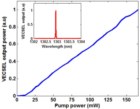
Fig. 3 shows experimental output characteristic curve for pumping with RCP light. This figure shows the output power as a function of incident pump power. The threshold is determined to be at a pump power of 11 mW with esti-mated external cavity length of 2–3lm. It should be noted that the threshold and efficiency of the device increases and decreases, respectively, when the fiber is moved away from the sample. This might be due to the coupling losses associ-ated with small alignment changes.
Lasing action could be observed at different wave-lengths between 1290–1315 nm, depending on the air-gap length between the sample and the interface of the coated fiber, and also the pump beam spot position on the sample. The CW lasing spectrum of the QD spin-VECSEL at a pump power of 90 mW measured at room temperature is shown in the inset in Fig. 3. The spin-VECSEL showed single mode lasing at 1303 nm with a very clear and narrow peak.
To evaluate the output polarization ellipticity (e) (defined as the ratio of the degree of circular polarizationDOCPto the total degree of polarizationDOPof the emission of the spin-VECSEL as defined in Eq.(1)), the RCP or LCP input com-ponents of pump (gþ) or (g) and the corresponding outputs of the spin-VECSEL (Iþ) and (I), respectively, were detected and analyzed using the free space and in-line polarimeters
[image:4.612.53.387.55.232.2]FIG. 2. Schematic diagram of the 1300 nm QD microcavity spin-VECSEL. The inset is a zoom of the QD spin-VECSEL design arrangement. OSA: Optical spectrum analyzer.
[image:4.612.324.552.556.734.2]e¼IþI IþþI
; (1)
P¼gþg
gþþg: (2)
Experimentally, Stokes vector elements {S0, S1, S2, S3} can be measured by the polarimeter and the value of the output polarization ellipticity (e) is calculated from these elements.
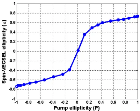
Fig.4depicts the output polarization ellipticity (e) as a function of the pump polarization (P), defined in Eq.(2), at pump of 60 mW and estimated external cavity length of 5–6lm. It shows that the polarization ellipticity (e) of the VECSEL follows that of the pump (P) but with inverted sign. When manually changing the pump polarization from right to left circular polarization or vice-versa, a correspond-ing switch from left to right circular polarization of the VECSEL occurred. This confirms spin polarized injection into the active region of the device. Similar behavior has been reported by Hovelet al.,19and it has been attributed to the reflection geometry. In contrast, since our VECSEL emits in the orthogonal mode under linearly polarized pump-ing (equivalent to electrical current biaspump-ing), by analogy it should emit in the orthogonal circularly polarized mode with respect to the polarization of the pump. We attribute this to the combined effects of the birefringence and dichroism pa-rameters of the device material.
However, it should be mentioned that there are some regions of the sample where, when the HR fiber is nearer the sample, the output polarization ellipticity (e) of the spin-VECSEL switches gradually to the same sign as that of the pump. Such a positional change leads to variations in the spatial profile of the optical pump beam at the wafer surface as well as a change in the cavity. While we see greater sensi-tivity as the spot is moved away from the heatsink, sugges-tive of local thermally induced changes in birefringence, further work would be needed to confirm the root cause fac-tors. In these regions, the output polarization ellipticity (e) follows that of the pump with the same sign as shown in Fig.
5 which was measured at the same pump power but with
shorter external cavity length of 1–2lm.
This figure also reveals that the degree of output polar-ization (between 0.1–0.6) is higher than the polarpolar-ization degree of the pump which demonstrates spin amplification. Our results show that, when pumped CW well above thresh-old, ellipticities up to 0.84 and 0.73 could be achieved with inverted and normal sign, respectively, with respect to that of the pump. The difference between the degrees of elliptic-ity in the two cases is suggestive of gradual polarization switching caused by the effects mentioned earlier. However, understanding the differences between different trends in Figs.4and5will be the subject of future work by conduct-ing further spectroscopic studies of the spin-VECSEL.
The controllability of the output polarization ellipticity by that of the pump is a well-known feature of spin-polarized lasers. It has been previously reported for pulsed operation37 with degrees of circular polarization close to unity and for continuous excitation at short18,38 and long20
wavelengths. The DOCP under CW operation is usually
lower than under pulsed excitation due to sample heating caused by the continuous pumping.
Using an external cavity formed by employing an HR-coated fiber as the top mirror, we have demonstrated an optically pumped InAs/InGaAs QD-based spin-VECSEL
operating at the important wavelength of 1300 nm.
Circularly polarized lasing under CW optical spin injection is shown at room temperature with pump threshold of 11 mW. We have analyzed the dependence of the output polarization ellipticity (e) of the spin-VECSEL on that of the pump (P). Our results reveal that the output polarization el-lipticity of the spin-VECSEL emission can exhibit either the same handedness as that of the pump polarization or the op-posite, depending on the experimental operating conditions.
We thank the Engineering and Physical Sciences Research Council (EPSRC) National Centre for III-V Technologies for supporting this work through their pump-priming scheme and N. Laurand (University of Strathclyde) for helpful advice concerning coated fiber supply.
1S. Datta and B. Das,Appl. Phys. Lett.
56, 665 (1990). 2
[image:5.612.146.203.50.107.2]J. Sinova and I. Zutic´,Nat. Mater.11, 368 (2012). FIG. 4. Inverted spin-VECSEL output polarization ellipticity (e) as a
[image:5.612.324.551.52.232.2]func-tion of the polarizafunc-tion ellipticity of the CW pump (P).
FIG. 5. Normal spin-VECSEL output polarization ellipticity (e) as a func-tion of the polarizafunc-tion ellipticity of the CW pump (P).
[image:5.612.61.287.563.743.2]3Semiconductor Spintronics and Quantum Computation, edited by D. Awschalom, D. Loss, and N. Samarth (Springer, Berlin, 2002).
4
R. Fiederling, M. Keim, G. Reuscher, W. Ossau, G. Schmidt, A. Waag, and L. W. Molenkamp,Nature402, 787 (1999).
5W. M. Chen and I. A. Buyanova,Handbook of Spintronic Semiconductors (Pan Stanford Publishing, Singapore, 2010).
6
Handbook of Spin Transport and Magnetism, edited by E. Y. Tsymbal and I. Zutic (CRC, Boca Raton, FL, 2011).
7
S. A. Wolf, D. D. Awschalom, R. A. Buhrman, J. M. Daughton, S. von Molnar, M. L. Roukes, A. Y. Chtchelkanova, and D. M. Treger,Science 294, 1488 (2001).
8N. C. Gerhardt and M. R. Hofmann,Adv. Opt. Technol.2012, 268949. 9C. Rinaldi, M. Cantoni, D. Petti, A. Sottocorno, M. Leone, N. M. Caffrey,
S. Sanvito, and R. Bertacco,Adv. Mater.24, 3037 (2012). 10
S. H€ovel, N. C. Gerhardt, M. R. Hofmann, F.-Y. Lo, A. Ludwig, D. Reuter, A. D. Wieck, E. Schuster, H. Wende, W. Keune, O. Petracic, and K. Westerholt,Appl. Phys. Lett.93, 021117 (2008).
11
V. G. Truong, P.-H. Binh, P. Renucci, M. Tran, Y. Lu, H. Jaffre`s, J.-M. George, C. Deranlot, A. Lema^ıtre, T. Amand, and X. Marie,Appl. Phys. Lett.94, 141109 (2009).
12J. Zarpello, H. Jaffre`s, J. Frougier, C. Deranlot, J. M. George, D. H. Mosca, F. Freimuth, Q. H. Duong, P. Renucci, and X. Marie,Phys. Rev. B 86, 205314 (2012).
13X. Jiang, R. Wang, R. M. Shelby, R. M. Macfarlane, S. R. Bank, J. S. Harris, and S. S. P. Parkin,Phys. Rev. Lett.94, 056601 (2005).
14
C. J. Chang-Hasnain, J. P. Harbison, G. Hasnain, A. C. Von Lehmen, L. T. Florez, and N. G. Stoffel,IEEE J. Quantum Electron.27, 1402 (1991). 15M. Holub and P. Bhattacharya,J. Phys. D: Appl. Phys.40, R179 (2007). 16S. Hovel, N. C. Gerhardt, C. Brenner, M. R. Hofmann, F.-Y. Lo, D.
Reuter, A. D. Wieck, E. Schuster, and W. Keune,Phys. Status Solidi A 204, 500 (2007).
17H. Ando, T. Sogawa, and H. Gotoh,Appl. Phys. Lett.73, 566 (1998). 18N. Gerhardt, S. Hovel, M. Hofmann, J. Yang, D. Reuter, and A. Wieck,
Electron. Lett.42, 88 (2006). 19
S. Hovel, A. Bischoff, N. C. Gerhardt, M. R. Hofmann, T. Ackemann, A. Kroner, and R. Michalzik,Appl. Phys. Lett.92, 041118 (2008).
20
K. Schires, R. Al Seyab, A. Hurtado, V.-M. Korpij€arvi, M. Guina, I. D. Henning, and M. J. Adams,Opt. Express20, 3550 (2012).
21
J. Lee, R. Oszwałdowski, C. Gøthgen, and I. Zutic, Phys. Rev. B 85, 045314 (2012).
22G. Boeris, J. Lee, K. Vyborny, and I. Zutic,Appl. Phys. Lett.
100, 121111 (2012).
23
J. Lee, S. Bearden, E. Wasner, and I. Zutic,Appl. Phys. Lett.105, 042411 (2014).
24N. C. Gerhardt, M. Y. Li, H. Jahme, H. Hopfner, T. Ackermann, and M. R. Hofmann,Appl. Phys. Lett.99, 151107 (2011).
25J. Lee, W. Falls, R. Oszwaldowski, and I. Zutic´,Appl. Phys. Lett.
97, 041116 (2010).
26
H. Hopfner, M. Lindemann, N. C. Gerhardt, and M. R. Hofmann,Appl. Phys. Lett.104, 022409 (2014).
27J. Rudolph, D. H€agele, H. M. Gibbs, G. Khitrova, and M. Oestreich,Appl.
Phys. Lett.82, 4516 (2003). 28
J. Rudolph, S. Dohrmann, D. Hagele, M. Oestreich, and W. Stolz,Appl. Phys. Lett.87, 241117 (2005).
29
D. Basu, D. Saha, and P. Bhattacharya, Phys. Rev. Lett. 102, 093904 (2009).
30
N. C. Gerhardt, H. H€opfner, M. Lindemann, and M. R. Hofmann,Proc. SPIE9167, 916703 (2014).
31M. Holub, J. Shin, D. Saha, and P. Bhattacharya, Phys. Rev. Lett.
98, 146603 (2007).
32
D. Basu, D. Saha, C. C. Wu, M. Holub, Z. Mi, and P. Bhattacharya,Appl. Phys. Lett.92, 091119 (2008).
33D. Saha, D. Basu, and P. Bhattacharya,Phys. Rev. B
82, 205309 (2010). 34
M. Holub, J. Shin, S. Chakrabarti, and P. Bhattacharya,Appl. Phys. Lett. 87, 091108 (2005).
35P. Bhattacharya, M. Holub, and D. Saha, Phys. Status Solidi C3, 4396 (2006).
36
H. Fujino, S. Koh, S. Iba, T. Fujimoto, and H. Kawaguchi,Appl. Phys. Lett.94, 131108 (2009).
37S. Iba, S. Koh, K. Ikeda, and H. Kawaguchi,Appl. Phys. Lett.98, 081113 (2011).
38
J. Frougier, G. Baili, M. Alouini, I. Sagnes, H. Jaffre`s, A. Garnache, C. Deranlot, D. Dolfi, and J.-M. George, Appl. Phys. Lett. 103, 252402 (2013).
39K. Hsu, C. M. Miller, D. Babic, D. Houng, and A. Taylor,IEEE Photonics
Technol. Lett.10, 1199 (1998). 40
N. Laurand, S. Calvez, M. D. Dawson, T. Jouhti, J. Konttinen, and M. Pessa,Phys. Status Solidi C2, 3895 (2005).
41S. S. Alharthi, E. Clarke, I. D. Henning, and M. J. Adams, in Proceedings of IEEE International Semiconductor Laser Conference (ISLC), Mallorca, Spain, 7–10 September 2014.
42S. S. Alharthi, E. Clarke, I. D. Henning, and M. J. Adams,IEEE Photonics
Technol. Lett.27, 1489 (2015). 43
O. G. Okhotnikov,Semiconductor Disk Lasers: Physics and Technology (Wiley-VCH Verlag GmbH and Co., Weinheim, 2010).
44D. Bimberg, N. Kirstaedter, N. N. Ledentsov, Z. I. Alferov, P. S. Kopev, and V. M. Ustinov,IEEE J. Sel. Top. Quantum Electron.3, 196 (1997). 45
P. Bhattacharya, D. Basu, A. Das, and D. Saha,Semicond. Sci. Technol. 26, 014002 (2011).