COMPARATIVE EVALUATION OF POSITIONAL ACCURACY OF IMPLANTS WITH TWO DIFFERENT SPLINTING MATERIALS USING
TWO DIFFERENT ELASTOMERIC IMPRESSION MATERIALS - AN INVITRO STUDY.
Dissertation submitted to
THE TAMILNADU Dr. M.G.R. MEDICAL UNIVERSITY In partial fulfillment for the degree of
MASTER OF DENTAL SURGERY
BRANCH – I
PROSTHODONTICS AND CROWN AND BRIDGE
MAY -2019
THE TAMILNADU Dr. M.G.R. MEDICAL UNIVERSITY CHENNAI – 600032
CERTIFICATE - I
This is to certify that the dissertation titled
“COMPARATIVE
EVALUATION OF POSITIONAL ACCURACY OF IMPLANTS
WITH TWO DIFFERENT SPLINTING MATERIALS USING
TWO DIFFERENT ELASTOMERIC IMPRESSION MATERIALS
- AN INVITRO STUDY. ” is a bonafide work done by
Dr.
A.KAYATHRI, Postgraduate student, during the course of the study for
the degree of “Master of Dental Surgery” in Department of
PROSTHODONTICS AND CROWN & BRIDGE, CSI College of
Dental Sciences and Research, Madurai during the period of 2016-2019,
under our supervision and guidance.
Dr. B.SIVA SARANYA, MDS Dr.R.LAMBODHARAN, MDS
Guide Professor and Head,
Dept. of Prosthodontics Dept.of prosthodontics
and Crown and bridge, and Crown and bridge
CSI College of Dental Sciences CSI College of Dental Scienc
and Research,Madurai and Research,Madurai
Dr.K.THANVIR MOHAMED NIAZI, MDS
Principal,
DECLARATION BY THE CANDITATE
TITLE OF DISSERTATION
COMPARATIVE EVALUATION OF
POSITIONAL ACCURACY OF IMPLANTS WITH TWO DIFFERENT SPLINTING MATERIALS USING TWO DIFFERENT ELASTOMERIC IMPRESSION MATERIALS - AN INVITRO STUDY.
PLACE OF STUDY CSI COLLEGE OF DENTAL SCIENCES AND RESEARCH, MADURAI
DURATION OF COURSE 3 YEARS
NAME OF THE GUIDE Dr. B.SIVA SARANYA MDS.,
HEAD OF THE DEPARTMENT Dr.R.LAMBODHARAN MDS.,
I hereby declare that no part of the dissertation will be utilized for gaining
financial assistance for research or other promotions without obtaining prior
permission of the Principal, CSI College of Dental Science and Research, Madurai. In
addition, I declare that no part of this work will be published either in print or
electronic without the prior permission guide who has been actively involved in
dissertation. The author has the right to reserve the publication of work solely with
prior permission of the Principal, CSI College Dental Sciences and Research,
Madurai.
CERTIFICATE – II
PLAGIARISM CERTIFICATE
This is to certify that this dissertation work titled “COMPARATIVE EVALUATION OF POSITIONAL ACCURACY OF IMPLANTS WITH TWO
DIFFERENT SPLINTING MATERIALS USING TWO DIFFERENT
ELASTOMERIC IMPRESSION MATERIALS - AN INVITRO STUDY” of the candidate Dr. A.KAYATHRI for the award of MASTER OF DENTAL SURGERY in the BRANCH I – PROSTHODONTICS AND CROWN AND BRIDGE.
On verification with the urkund.com website for the purpose of plagiarism
Check, the uploaded thesis file contains from introduction to conclusion pages and
result shows 10 percentage of plagiarism in the dissertation.
Date:
Place: Madurai
Guide sign HOD sign with Seal
DR.A.KAYATHRI.,
Post Graduate student, Dept. of Prosthodontics & crown& bridge, CSI college of
Dental Sciences
&Research, Madurai.
DR.B.SIVA SARANYA.,MDS
Reader,
Dept. of Prosthodontics & crown& bridge, CSI college of
Dental Sciences
&Research, Madurai.
Dr. R.LAMBODHARAN., MDS,
Professor and Head, Dept. of Prosthodontics & crown& bridge, CSI college of
Dental Sciences
ACKNOWLEDGEMENT
I express my sincerest and at most thanks to Dr.R.LAMBODHARAN., MDS,
Professor & Head, Department of Prosthodontics, CSI College of Dental Science and
Research, Madurai. He is an inspiration to all and has provided me full support,
encouragement and motivation for completion of this dissertation.
My heartful thanks to Dr. B.SIVA SARANYA, MDS, Reader, Department of
Prosthodontics, CSI College of Dental Sciences and Research, Madurai, who has
guided me with constant support whenever necessary. Her guidance and mentorship
has been the navigation for my dissertation, without whose help the completion of this
dissertation wouldn’t have been possible.
I am deeply grateful to Dr.K.THANVIR MOHAMED NIAZI, MDS
Principal, C.S.I College of Dental Sciences and Research for his kind permission,
encouragement and for providing me with all the facilities needed to complete this
work.
It gives me great pleasure to thank the staff members,Dr.K.Babu Rajan MDS,
Dr.P.Jesu Doss MDS, Dr.S.Sabarinathan MDS, Dr.S.Deenadayalan MDS,
Dr.R.MuthuKumar MDS, Dr.C.Divagar MDS, Department of Prosthodontics,
C.S.I College of Dental Sciences and Research, Madurai, for their valuable insights
during my study.
I am indebted to all my Family members. My love and gratitude for them can
hardly be expressed in words. I take this opportunity to thank them for supporting me
I would like to take this opportunity to thank my co pgs Dr.J.DhivyaPriya,
Dr.Vaishnavi.V.S who provided me with the much needed support and constant
motivation over the course of the study.
I take this opportunity to express my thanks to the Non-Teaching Staffs of the
department, who have helped me directly or indirectly in the making of this
dissertation.
I thank the LORD ALMIGHTY for providing me this opportunity and
CONTENTS
S.NO TITLE PAGE.NO
1 INTRODUCTION 1
2 REVIEW OF LITERTURE 6
3 MATERIALS AND METHODS 16
4 RESULTS 29
5 DISCUSSION 51
6 CONCLUSION 60
7 SUMMARY 67
LIST OF TABLES Table
No :
Title Page No.
1 Basic Values, Mean and Standard Deviation of Inter
Implant Distance in X-Axis for the Group I (A) samples.
31
2 Basic Values, Mean and Standard Deviation of Inter
Implant Distance in Y-Axis for the Group I (A) samples.
31
3 Basic Values, Mean and Standard Deviation of Inter
Implant Distance in Z-Axis for the Group I (A) samples
32
4 Basic Values, Mean and Standard Deviation of Implant
Angulation to Horizontal Plane in Z-Axis for the
Group I (A) samples.
32
5 Basic Values, Mean and Standard Deviation of Inter
Implant Distance in X-Axis for the Group II (A) samples.
33
6 Basic Values, Mean and Standard Deviation of Inter
Implant Distance in Y-Axis for the Group II (A) samples.
33
7 Basic Values, Mean and Standard Deviation of Inter
Implant Distance in Z-Axis for the Group II(A) samples.
34
8 Basic Values, Mean And Standard Deviation of Implant
Angulationto Horizontal Plane in Z-Axis for the
Group II (A) samples.
34
9 Basic Values, Mean and Standard Deviation of Inter
Implant Distance in X-Axis for the Group I (B) samples.
35
10 Basic Values, Mean and Standard Deviation Of Inter
Implant Distance in Y-Axis for the Group I (B) samples.
11 Basic Values, Mean and Standard Deviation of Inter
Implant Distance in Z-Axis for the Group I (B) samples.
36
12 Basic Values, Mean and Standard Deviation of Implant
Angulation to Horizontal Plane in Z-Axis for the
Group I (B) samples.
36
13 Basic Values, Mean and Standard Deviation of Inter
Implant Distance in X-Axis for the Group II (B) samples.
37
14 Basic Values, Mean and Standard Deviation of Inter
Implant Distance in Y-Axis for the Group II (B) samples.
37
15 Basic Values, Mean and Standard Deviation Of Inter
Implant Distance in Z-Axis for the Group II (B) samples.
38
16 Basic Values, Mean and Standard Deviation Of Implant
Angulation to Horizontal Plane in Z-Axis for the
Group II (B) samples.
38
17 Difference in Inter-Implant distance in X-Axis 39
18 Difference in Inter-Implant distance in Y-Axis 40
19 Difference in Inter-Implant distance in Z-Axis 41
20 Difference in Implant angulation to Horizontal Plane in
Z-Axis
42
21 Comparison of Inter-Implant Distance in X-Axis 43
22 Comparison of Inter-Implant Distance in Y-Axis 45
23 Comparison of Inter-Implant Distance in Z-Axis 47
24 Comparison of Implant angulation to Horizontal Plane in
Z-Axis
ANNEXURE II
LIST OF FIGURES
Figure No: Title
Fig:1 Modelling Wax
Fig:2 Heat cure acrylic resin
Fig:3 Cold cure acrylic resin
Fig:4 Pattern Resin
Fig:5 ProtempTM4 Temporization Material
Fig:6 EXA’lence VPES Impression Material
Fig:7 EXAMIXTMNDS Impression Material
Fig:8 Honigum-Putty Impression Material
Fig:9 Tray Adhesive
Fig:10 Die Stone
Fig:11 Alginate
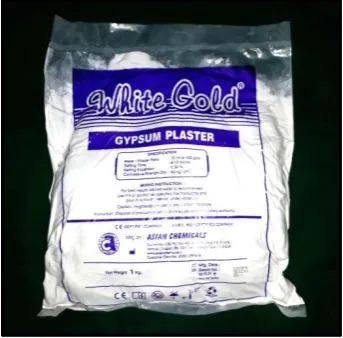
Fig:12 Plaster of Paris
Fig:13 Mis seven demo implant
Fig:14 Mis implant analog internal hex
Fig:15 Mis open tray impression coping
Fig:16 Custom made mould
Fig:17 Wax Knifeand Carver
Fig:18 Laboratory Micromotor with Acrylic Trimmer
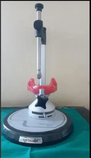
Fig:20 Surveyor
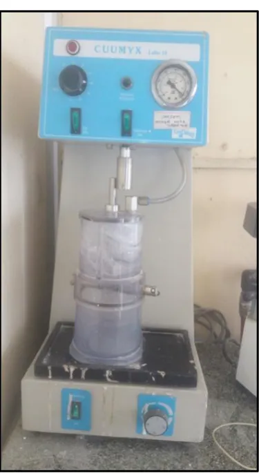
Fig:21 Vaccum mixer with vibrator
Fig:22 Edentulous mandibular mould
Fig:23 Co-ordinate Measuring Machine
Fig:24 Custom trays
Fig:25 Alpha Bio Torque wrench
Fig:26 Dental flask with clamp
Fig:27 A Wax Model
Fig: 28 A Wax Model mounted on Surveyor
Fig:29 Reference Model
Fig:30 Primary Cast
Fig:31 Wax placed Primary Cast
Fig:32 Flasking Done
Fig:33 Reference model was splinted with pattern resin
Fig:34 Putty Index
Fig:35 Reference model was splinted with BisGMA Material
Fig:36 Impression removed from the reference model
Fig:37 Master Cast
Fig:38 Co-ordinate Measuring Machine
Fig: 39 Measuring from implant replica 1 is taken as zero(Left to Right).
ANNEXURE III LIST OF GRAPHS
Graph No: Title
Graphs:1 Comparison of Inter-Implant distance in X-Axis Values
Graphs:2 Comparison of Inter-Implant distance in X-Axis(D1X)
Graphs:3 Comparison of Inter-Implant distance in X-Axis(D2X)
Graphs:4 Comparison of Inter-Implant distance in X-Axis(D3X)
Graphs:5 Comparison of Inter-Implant distance in Y-Axis Values
Graphs:6 Comparison of Inter-Implant distance in Y-Axis(D1Y)
Graphs:7 Comparison of Inter-Implant distance in Y-Axis(D2Y)
Graphs:8 Comparison of Inter-Implant distance in Y-Axis(D3Y)
Graphs: 9 Comparison of Inter-Implant distance in Z-Axis Values
Graphs:10 Comparison of Inter-Implant distance in Z-Axis(D1Z)
Graphs:11 Comparison of Inter-Implant distance in Z-Axis(D2Z)
Graphs:12 Comparison of Inter-Implant distance in Z-Axis(D3Z)
Graphs: 13 Comparison of Implant angulation to Horizontal Plane in Z-Axis
Graphs:14 Comparison ofImplant angulation to Horizontal Plane in Z-Axis (Angle 1)
Graphs:15 Comparison of Implantangulation toHorizontal Plane in Z-Axis (Angle:2)
Graphs:16 Comparison of Implant angulation to Horizontal Plane in Z-Axis (Angle:3)
Graphs:17 Comparison of Implant angulation to Horizontal Plane in Z-Axis (Angle:4)
Graph:18 Difference In Inter-Implant Distance In X-Axis
Graph:19 Difference In Inter-Implant Distance In Y-Axis
Graph:20 Difference In Inter-Implant Distance In Z-Axis
INTRODUCTION
Osseointegrated implants have provided better result than conventional
complete denture prosthesis for the edentulous patients38. The use of dental
implant is one of the fixed treatment option given to the patient. The
endosseous implants have showed the higher survival rates and long term success
rate. The diagnosis and treatment planning, gentle surgical procedure, accurate
impression making, passive fit of prosthesis, development of proper occlusion
scheme and recall maintenance are the important factor for the success rate of
implant. The failure of implant may be due to improper surgical procedure,
inaccurate prosthodontic procedure, lack of passive fit of prosthesis, presence of
occlusal discrepancies17.
One of the important factor for long term implant success is dependent
upon the accurate design of prosthesis which should have an impeccable, passive fit
to the implant. This prevents mechanical and biological failures in implant treatment.
The biomechanical problems like screw loosening, fatigue, fracture of implant
components, peri- implantitis, bone loss and later disintegration occur due to lack
of passive fit of the frame work9. This is the matter of greater concern especially
in multiple implant conditions such as partially edentulous and fully edentulous
situations.
Various clinical studies have been reported that range of 10µm to 15µm is
acceptable level of discrepancy of the framework25. The precise transfer of the
spatial relationships of implants from mouth to the master cast with an accurate
impression procedure is the first and critical step for designing the passive fit
of implant framework29. The accurate inter implant relationship in working cast
is obtained by the accurate impression techniques. Recent lab procedures like
CAD/CAM with digital impression technique, soldering procedure, laser welding
are some of the procedure that are followed to fabricate an impeccable passive
prosthesis.
The ultimate goal of passively fitting implant prosthesis is an important
factor in implant dentistry is achieved using accurate transfer of implant
position to working cast. The various factors influence the accuracy of
impression are impression technique, different connection level (implant level
and abutment level), different impression trays, impression material, implant depth,
time delay for stone pouring30.
The splinting of impression copings is necessary for accurate implant
impression in multiple implant situations. There various types of
impression techniques include direct and indirect impression technique and
impression material, available for implant impression making9,48.
Indirect impression technique (closed tray) involves the use of tapered
impression copings which do not get picked up in the impression. It needs the
repositioning of impressions with analogs attached back to the impression. The
advantages of this technique is that the implant replicas are visually fastened
to the impression copings and therefore ensuring its complete seating. The
disadvantages of this technique is reseating of the copings in the impression
may not be accurate, which indicate the error in the inter implant relationship
in a vertical axis41,58.
Direct impression technique (open tray) uses impression copings that are
picked up in the impression and analogs are connected to the copings. The
advantage of this technique is coping remains in the impression and analogs
are attached to coping. This reduces the error during cast pouring55. Among the
direct impression technique, the splinted impression technique was more
accurate than the non-splinted impression technique 18,37.
Splinting of open tray impression copings has been suggested by many
authors in order to maintain a more accurate inter implant relationship, when
compared to that obtained with non-splinted copings. Although splinting with
pattern resin, impression plaster, silicones and bite registration polyether have
been used as splinting material in several studies15,39,29.Rigid splinting of
impression coping with pattern resin have been advocated to achieve accurate
open tray impression by various authors19.
Recently a newer material, Bis GMA was used to splint the impression
copings, because of its advantages such as easy handling, less time consuming,
less technique sensitive which is readily available46.
Impression materials such as vinyl polysiloxane (VPS) and polyether
(PE) impression materials are commonly used to produce final impression in
fixed and implant prosthodontics. VPS and PE exhibit excellent dimensional
stability under different test and storage condition. PE produced satisfactory
dimensional stability under dry and moist condition. PE produced better surface
details than VPS under moist conditions. In 2009, vinyl polyether silicone
impression material was commercially introduced. This impression material is
composed of VPS and PE and is promoted as a hydrophilic material. Various
studies proven the dimensional stability of this material. Studies comparing the
dimensional stability of VPES and PE materials showed similar results and
also VPES behaves more like PE. Hence VPES material was used in this study34.
Several methods have been advocated in the literature for comparing the
accuracy of impressions includes strain gauge method and measuring method.
Measurement of the distances between the implant replicas in the master model and
comparing them with that of the experimental model have been reported in the
previous studies. Devices like travelling microscope, digital micrometer, measuring
microscope, optical scanner, profile projector have been used for this
purpose 9,28,14,26,27,48,49,39. It is necessary to study the inter implant distances in x, y
and z axis and also the angular measurements in z-axis in order to study the linear and
rotational distortion of the impression copings and implant replicas. Coordinate
measuring machine (CMM) is an appropriate device to measure the inter implant
distances and angulations in the three axes. A Coordinate measuring machine
is a device which measures the distance of the analogs from a reference point in
the three different axes (x, y and z axes) and also calculate the amount of
rotational distortion, linear rotation, as well as measure the inter implant
angulation29,43.
Many studies evaluated the positional accuracy of implants with different
impression materials, and have reported higher positional accuracy with VPS
impression material. Also comparative studies on the positional accuracy of
implants with different splinting materials and have reported pattern resin
showed more accuracy47.Various impression materials and splinting techniques
are advocated in several studies but accuracy in impressions are still lacking.
In light of the above considerations, the aim of this study was conducted
to compare and evaluate the positional accuracy of implants with two different
splinting materials with two different elastomeric impression materials.
1. To evaluate the positional accuracy of implant using pattern resin
splinting material and impression making with Vinyl poly siloxane.
2. To evaluate the positional accuracy of implant using Bis GMA splinting
material and impression making with Vinyl poly siloxane .
3. To evaluate the positional accuracy of implant using pattern resin
splinting material and impression making with Vinyl poly ether silioxane.
4. To evaluate the positional accuracy of implant using Bis GMA splinting
material and impression making with Vinyl poly ether silioxane.
5. To compare the positional accuracy of implant using pattern resin
splinting material and impression making with Vinyl poly siloxane and
Vinyl poly ether silioxane.
6. To compare the positional accuracy of implant using Bis GMA splinting
material and impression making with Vinyl poly siloxane and Vinyl poly
ether silioxane.
7. To analyse the comparative evaluation of the positional accuracy of
implant impression using pattern resin and Bis GMA splinting material
and impression making with Vinyl poly siloxane and Vinyl poly ether
silioxane.
REVIEW OF LITERATURE
W.B.Eamest et al (1979)12 There are five steps involves in achieving accurately fitting casting are impression material, die, wax pattern, investment
and casting procedure. The impression materials are chosen according to their
accuracy, dimensional stability, working time, shelf life, electroplating capabilities
and taste.
Mark R.Spector et al (1990)44 The passively fitting prosthesis is important for fabrication of superstructure which is fitted into osseointegrated implants.
The failure in passive fit lead to loss of fixture integration, progressive
treatment failure. The micro fractures of a bone caused due to forced tightening
of the superstructure.
Robert M.Humphries et al (1990)21 Oral rehabilitation success is dependent
on the accurate registration of structure that supports the prosthesis.
The impression must be accurate and then only master cast duplicate the clinical
condition. The accuracy of master casts fabricated from three impression
techniques commonly used with the Branemark system was measured.
Alan B.Carr et al (1991)10 A five implant mandibular model was used to produce seven casts by both the indirect and direct transfer coping
technique. The dental cast framework fitted to the master cast is compared for
accuracy of the technique used. The direct impression techniques with open tray
provide better accuracy.
Alan B.Carr et al (1992)11 The understanding of the accuracy and precision of all phases of fabrication and connection, is required for passively fitting implant
superstructures. There was no significant difference was found between the
splinted and unsplinted indirect technique on comparing.
Paolo Vigolo et al (1993)50 The achievement of an accurate passive fit of a prosthesis on osseointegrated implants obviously demands an accurate master cast.
An endosseous implant distributes the physiologic load imposed on it into the
supporting tissues. The maximum accuracy is achieved by splinting the transfer
coping together with any resin materials.
Chi-Chi Hsu et al (1993)20 An accurate master cast is a prerequisite for the fabrication of a precise dental prosthesis. The accurate transfer impression procedure
is important for construction of implant superstructure and it help in avoiding
the prosthesis errors.
J.N.Walton (1994)54 The clinical problems such as unstable occlusion, improper oral hygiene, speech difficulties are caused due to improper fit of
prosthesis to the implant. Evaluating the success of an implant-supported prosthesis
includes assessing maintenance needs, specifically adjustments and repairs, and
patient satisfaction.
David Assif (1996)3 The misfit of implant supported prosthesis due to the lack of tensile, compressive and bending forces. A primary factor in increasing the
precision fitting of prosthesis is dependent on the accurate impression procedure.
The direct impression technique shows better accuracy.
Gamal Burawi (1997)8 Accurate impressions and working casts are essential for conventional prosthodontics procedures on natural abutment. A passive fit of
framework to the abutments of the osseointegrated implant supported prosthesis
is important for the success of the restoration.
Joseph Y.K.Kan (1999)25 The successful long term osseointegration is depends upon passive fit of implant framework and underlying structure. The
acceptable level of misfit of prosthesis to the implant support prosthesis is 150µm
is said by Jemt.
Alving.Wee (2000)55 The impression made with polyether and addition silicones are not having any significant difference between the accuracy of
direct implant impression said by Barret et al.
M.Lorenzoni (2000)31 The impression material polyether and polyvinylsiloxane is particularly suitable because of their favourable physical
characteristics, their stability with regard to dimension.
Jason Burns (2003)9 The rigid custom trays produced significantly more accurate impression than polycarbonate stock trays. Direct impression copings
procedure more accurate impressions. The rigid elastomeric impression material
maintains impression accurately and dimensionally stable.
Charles J.Goodcare (2003)17 The surgical complications, implant loss, bone loss, peri-implant soft tissue complications, mechanical complications, and
esthetics/phonetics complication are six major categories of complication have
been reported.
Paolo Vigolo (2003)49 The verification of cast procedure in the framework fabrication process is done by the framework reorientation procedure. The cross
wing design that was rotated into contact with an adjacent coping and
connected with autopolymerizing acrylic resin.
Paolo Vigolo (2004)48 The definitive cast was achieved due the splinting of square impression copings joined together by autopolymerizing acrylic resin
is improve the accuracy of cast. The implant has 4mm deep internal engagement
with thick coronal walls and uses a system of engagement that confirms proper
seating of different components.
Eduardo Batista Franco (2007)14 Vinylpolysiloxane suggested to be more dimensionally stable than polysulfide and condensation silicones. Because of the
dimensional stability of vinylpolysiloxane became popular material for dental
impression. The stability of material depends on extact moment of pouring stone
dies. To avoid the distoration of the impression.
Sina Jannesar (2007)23 To make implant impression by using modified dual impression technique using the custom tray. This impression technique used to
register the residual ridge under the load and anatomic condition using two impression
materials.
Assuncao Wiriey Goncalves (2008)4 The accuracy of impression procedure is one of important factor for success of implant prosthesis. The airborne
adhesive-coated on impression coping. To decrease the micro movement of coping inside the
impression material from impression making to cast pouring and to increase the
accuracy of the cast.
Heeje Lee (2008)28 There was no effect of implant depth on the dimensional accuracy. During the cast fabrication procedure, the splint technique was more
accurate this was due to accuracy of the implant impression over multiple
laboratory procedures.
Mary P.Walker (2008)53 The impression technique affects the accuracy of the cast which may lead to misfit of prosthesis. The indirect impression technique
using screw-on metal impression at implant level yield more accuracy than
abutment level impression.
Hans-JurgenWenz (2008)56 The long- term clinical success of the implant restoration depends upon accuracy of impression material used, passive fit of the
prosthesis. The dimensional accuracy achieved by non-splinted direct technique or
splint indirect technique, impression material used was addition cured silicone
result in most accurate cast.
Heeje Lee (2008)30 The rigidity to hold the impression copings and to prevent accidental displacement. The minimal positional distortion between
implant replica are the two requirements for impression material for the direct
implant impression technique.
Humberto Gennari Filho (2009)13 During the transfer impression technique, the square coping was splinted using prefabricate acrylic resin, have decreased the
polymerization shrinkage and increase the system stability.
Hariharan Ramasubramanian (2010)19 In direct technique both splinting and non-splinting have been advocated for accurate impression. Splinting the
impression copings helps in rigidity and dimensional stability of such interocclusal
recording materials.
Glen H.Johnson (2010)24 The dual arch tray with VPS produce greater success than full tray with PE. The VPS impression material shows greater
impression success during implant level impression procedure. The VPS impression
material was most commonly used material.
Sujatha S.Reddy (2011)45 The VPS impression material have better elasticity and dimensional stable in comparison to polyethers. So VPS is most
widely used impression material in restorative and prosthetic dentistry.
Sang-Jik Lee (2011)29 VPS bite registration material used as splinting material is better than acrylic resin splint and unsplinted group. The impression
made with square impression coping.
D.R.Prithiviraj (2011)38 In order to make the exact position of the implants during the processing of the master cast and which help in passivity of
the framework casting to it supporting abutments without interference between
the prosthesis connections is achieved by accuracy of impression procedure is
one of most important factor for success of implant prosthesis.
D Ongul (2012)35 Splinting impression copings with acrylic resin provide better result than the non-splinted techniques or splinted using a light curing
composite. Clinical situations where impressions of multiple implants in
edentulous arches must be made and the pick-up implant impression technique
is used.
Preeti Agarwal Katyayan (2012)26 There two forms of hydrophobic nature of VPS impression material. The first form describes the surface energy of
unpolymerized liquid phase of the impression material. The ability to moist the oral
tissues during impression making. The second form describe the surface energy of
the solid polymerized VPS and the high contact angle that ideally forms when the
VPS impression material are moist with dental gypsum material.
Ozcelik Tuncer Buark (2012)36 In implant supported over denture condition, the implant and soft tissues have different resilience. The functional impression
technique used to record the both mucosa and implant components along the alveolar
tissues in the same time. The major benefit of this technique is that records implant
components and the supporting tissue in accurate manner.
G.Vivekananda Reddy (2012)51 The nature of impression material to be used is important to achieve an impression with accurate details of oral
structure. The contact angle play the important role in determining the nature of
the impression material and to make an accurate cast
Oliver Schaefer (2012)41 The parameters such as impression material, tray selection, rheological properties, impression technique are help to achieve the
accuracy. The wetting behaviour, moisture displacement capability, flow under
pressure are physiochemical properties have also been investigated as important
character for accuracy of impression.
Gracis et al (2012)18 The factors such as implant connection type, the design of the connection, lack of parallelism between multiple implants, the
impression materials and the technique employed has influence the accuracy of
implant level impression.
S Reddy (2013)40 The impression material like polyvinylsiloxane and polyether have similar dimensional accuracy for transfer procedures in parallel
and angulated implant. The impression making in parallel and angulated
implant polyvinylsiloxane and polyether material are recommended.
Nassar et al (2013)34 The Exalence impression material has the properties of both VPS and PE and has more dimensional stability property.
The cast pouring immediately after impression making is more accurate than
delayed pouring of cast.
Kurtulmus-Yilmaz S et al(2014)27 For parallel implants, more accurate impressions were obtained with splinted direct technique. The VPS shows most
accurate impression material and splinted direct technique was most accurate in
presence of angulated implant situations.
Sunantha Selvaraj (2014)46 The splinting material like acrylic resin and Bis GMA is used to splinted the impression copings together during implant level
impression in direct technique. On Comparison both the material exhibits same
results.
Pujari Malesh (2014)39 The cast obtained use of square impression coping is more accurate than non-modified impression coping during implant level impression.
The square impression coping is commonly used during implant level impression.
Alikhasi et al (2015)1 The implant impression materials like PVS and PE are most commonly, used impression material because of dimensionally stable due to the
polymerization reaction involves no loss by products. The PVS and PE have the good
physical and mechanical properties. It has more accurate surface detail reproduction.
Vojdani et al (2015)52 In clinic practice common finding during implant surgery, lack of implant parallelism and lack of parallelism between implant and
tooth. This is caused due to anatomical consideration and esthetics limitation. Implant
impression cause distortion because of undesirable path of impression with drawal.
Sreeramulu Basapogu (2016)6 In 1970 VPS impression material were introduced. The VPS is used implant dentistry because it has low polymerization
shrinkage, low creep property, good surface reproduction, dimensional stability,
because they do not release by product.
Prakash S (2016)37 The success of implant therapy depends upon the following factor impression techniques, like transfer and pickup technique, open and
closed techniques, splinted or nonsplinted techniques, accuracy of impression depends
upon the angulations of implant depth, copings used.
AyseGozde Turk (2016)5 The VPS and PE impression material were clinically acceptable material of choice in implant level impression. The accuracy of
impression material depends upon the composition of impression material, size of
filler particles, and fluid mechanics of flow into very small spaces.
Sonam Gupta (2017)43 The vinylsiloxanether, is the newer generation elastomeric material in combination of both polyvinylsiloxane and ployether material.
It has both material properties as one impression material. It is commercially available
material. It is used in implant dentistry.
Sama Nassar (2017)33 The small dimensional changes occur in the addition silicone and polyether at percentage of -0.15 to -0.20 respectively with half of the 24
hour contraction occur within the first hour after setting. The ploymerization due to
cross-linking and rearrangement of bonds in polymer chains cause contraction in
elastomeric impression material.
Jajira Nausheen (2017)22 The essential prerequisite for maintaining osseointegration is by passive fitting of prosthesis. There are two type of technique for
implant impression like direct and indirect technique. The dimensional accuracy of
implant definitive is depends upon the technique used, the open tray and closed tray
exhibits no significant difference on comparison.
MATERIALS AND METHODS
The aim of the present in-vitro study was conducted to compare and
evaluate the positional accuracy of implants with two different splinting materials
using two different elastomeric impression materials.
MATERIALS EMPLOYED:
Modelling Wax No:2 (Hindustan dental products, Hyderabad, India) (Fig:1)
Heat cure acrylic resin (DPI-Heat cure polymer and monomer, Mumbai, India)
(Fig:2)
Cold cure acrylic resin (DPI-cold cure polymer and monomer,Mumbai,India)
(Fig:3)
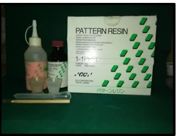
Pattern Resin (GC Corporation, Tokyo) (Fig:4)
ProtempTM4 Temporization Material (3M ESPE, Germany) (Fig:5)
EXA’lence VPES Impression Material (GC America) (Fig:6)
EXAMIXTMNDS Impression Material (GC America) (Fig:7)
Honigum-Putty Impression Material (DMG, Germany) (Fig:8)
Tray Adhesive (Coltene, Maharshtra) (Fig:9)
Die Stone (Pearl stone, Asian chemicals, Gujarat) (Fig:10)
Alginate (DPI Algitex, Karnataka) (Fig:11)
Plaster of Paris (White Gold, Asian Chemicals, Gujarat) (Fig:12)
Misseven demo implant standard platform with a dimension of
3.75x11.50mm (Fig:13)
Mis implant analog internal hex (Fig:14)
Mis open tray impression coping (Fig:15)
Custom made mould (Fig:16)
INSTRUMENTS AND EQUIPMENTS EMPLOYED:
Wax Knife and Lecron Carver (GDC,Hoshiarpur, Punjab) (Fig:17)
Laboratory Micromotor (NSK, Japan) (Fig:18)
Classic Rubber Bowl and Straight Spatula (GDC, Hoshiarpur, Punjab)
(Fig:19)
Surveyor (Bio art- Delineador, Netherlands) (Fig:20)
Vaccum mixer with vibrator,( Cuumyx, confident ,Bangalore) (Fig:21)
Edentulous mandibular mould ( Nissin, Japan) (Fig:22)
Co-ordinate Measuring Machine( Tesa, Chennai) (Fig:23)
Twenty Custom trays (Fig:24)
Torque wrench (Alpha – Bio, Israel) (Fig:25)
Dental flask with clamp (Jabbar, Uttar Pradesh) (Fig:26)
DESCRIPTION OF VINYL POLY SILOXANE (Monophase) IMPRESSION MATERIAL (VPS):
VPS is an elastomeric impression material because of its thixotropicity offers
exceptional dimensional stability, elastic recovery and tears strength, and “immediate
pour” capability. Since it is a hydrophobic material by adding surfactant enhances the
material's wetability, reducing contact angles and surface tension so it reaches all
areas for precise replication. It also allows stone to flow more evenly into the
impression and produce accurate models. VPS has excellent elastic recovery and tear
strength for easy removal with no distortion or damage to models. It offers stable
impressions that can be used up to two weeks26.
DESCRIPTION OF VINYL POLY ETHER SILICONE (Heavy body and Light body) IMPRESSION MATERIAL (VPES):
VPES impression material is a blend of a polyether and a vinyl polysiloxane
(VPS) material. This provides the hydrophilic (wetting) properties of a polyether
along with the higher tear strength of VPS that allows it to perform well in critical
area such as in the gingival sulcus. Better hydrophilicity means more precise flow
subgingivally with fewer voids and bubbles. Additionally, the better tear strength
subgingivally provides more accurate replication of the subgingival anatomy,
including the preparation margin, implant level impression34.
DESCRIPTION OF VINYL POLY SILOXANE (Putty) IMPRESSION MATERIAL:
VPS has excellent thixotropic property, precise detail reproduction and
outstanding stability in the tray as well as intraorally. It has remarkable flow
properties under light pressure, balanced hydrophilicity, and pleasant odour and has
adequate working time. It is used for crown and bridge, inlay/onlay,and full mouth
restorations.
DESCRIPTION OF PATTERN RESIN SPLINTING MATERIAL:
Pattern Resin is a self-curing, general purpose acrylic resin used for making
patterns for splinting the impression coping during implant impression. Fabrication of
copings for FPD, post and core build-ups, lingual and palatal bars, implant
attachments, adhesion bridges, clasps, telescopic crowns16. Certain pre-soldering
techniques also. It sets quickly with minimal shrinkage, allows both direct and
indirect pattern making, and leaves no residue after burnout.
DESCRIPTION OF BIS-GMA SPLINTING MATERIAL:
BisGMA temporisation material has set another milestone in temporary crown
and bridge materials. BisGMA has been applied its expertise in nanotechnology to
create the first bis-acrylic composite with a new generation of sophisticated fillers.
The result is unparalleled achievements in strength, handling and aesthetics. Reliably
tough temporaries due to its highest fracture resistance, better abrasion stability and
also suitable for long-term temporisation. It has the advantage of esthetics and a
comfortable fit through a smooth surface, natural shine, fluorescence and has higher
colour stability. Easy, fast handling and fabrication due to the reduced smear layer
and has good glossy surface.
DESCRIPTION OFCOORDINATE MEASURING MACHINE:
A coordinate measuring machine (CMM) is a device that measures the
geometry of physical objects by sensing discrete points on the surface of the object
with a probe. Various types of probes are used in CMMs, including mechanical,
optical, laser, and white light. Depending on the machine, the probe position may be
manually controlled by an operator or it may be computer controlled. CMMs typically
specify a probe's position in terms of its displacement from a reference position in a
three-dimensional Cartesian coordinate system (i.e., with X, Y, Z axes). In addition to
moving the probe along the X, Y, and Z axes, many machines allow the probe angle
to be controlled to allow measurement of surfaces that would otherwise be
unreachable. It is used to find out the angle formed between the axis of
implant to the base of the model and cast respectively to the horizontal.
METHODOLOGY:
I. Reference model fabrication
II. Evaluation of reference model using Coordinate measuring machine
III. Custom made mould
IV. Custom tray fabrication
a. Preparation of primary cast
b. Preparation of spaced primary cast
c. Fabrication of custom tray
d. Grouping of the Sample
V. Preparation of master casts
VI. Evaluation of master casts using Coordinate measuring machine
VII. Results and statistical evaluation
I. REFERENCE MODEL FABRICATION:
A wax model (Fig: 27) of the edentulous mandibular arch was obtained by
flowing modelling wax into an edentulous mold. The wax model was then mounted
on a dental surveyor (Fig: 28) and four implant replicas of 3.75x11.50mm MIS were
placed into the edentulous wax model in the mandibular symphyseal region to mimic
clinical situation. The analogs were placed in a manner such that the one of the
trilobes was facing labially. It was also ensured that the 2mm polished collar
remained outside the model to ensure visualisation in coordinate measuring machine.
Two stops were cut in the land area of the wax model, 2mm x 2mm, one on either side
molar region, to act as stops for the custom tray during impression making. The stops
were made to ensure similar orientation of all the custom trays on the reference
model. Cover screws were screwed on to the implant replicas and an acrylic reference
model was obtained by processing the wax model in heat cure acrylic resin (DPI Heat
cure, India) (Fig: 29). The reference model was finished and kept undisturbed for 24
hours.
II. EVALUATION OF REFERENCE MODEL USING COORDINATE MEASURING MACHINE:
The reference model was evaluated using a Coordinate measuring machine
(CMM, Tespa calibration centre, Chennai, India) which is capable of measuring in x,
y and z axes with an accuracy of ±5μm. The CMM was connected to a data processor
which gave the measured values. In order to measure the three dimensional accuracy
of the reference model, the inter implant distances in x, y and z axes were measured
and the angle between the implant replicas and base of the cast were evaluated. The
implant replicas were numbered 1 to 4 starting from the left to the right.
The probe used in the CMM was first calibrated. The reference model was
measured to obtain the reference values. The model was screwed in the base for
measuring. In order to obtain similar orientation of the reference model and all the
master casts, the centre of replicas1and4 were aligned in the CMM and then the
measurements were made.
Measurements were made in all the three axes namely x, y and z. The distance
between replica 1 and 2 was denoted as D1. The distance between replica 1and 3 was
denoted as D2. The distance between replica 1 and 4 was denoted as D3. The
angulation in replica1 was denoted as Angle 1. The angulation in replica 2 was
denoted as Angle 2. The angulation in replica 3 was denoted as Angle 3. The
angulation in replica 4 was denoted as Angle 4
Measuring distance in x axis:
The coordinates of the centre of replica 1 was measured and zeroed. Keeping
this position as a reference, the positions of the centre of replica 1 and 2(D1X), 1 and
3(D2X), and 1 and 4(D3X) were measured in the X plane x-axis.
Measuring distance in y axis:
The coordinates of the centre of replica 1 was measured and zeroed. Keeping
this position as a reference, the positions of the centre of replica 1 and 2(D1Y), 1 and
3(D2Y), and 1 and 4(D3Y) were measured in Y plane Y-axis.
Measuring distance in z axis:
Then the probe was used to measure the plane formed by the platform of
replica 1. The open tray impression copings were connected to the implant replicas
and screwed at 15Ncm torque46. The plane formed by the flat surfaces of each
impression coping were measured. The distance between the planes formed by the
replica platforms were measured. The distance between the plane formed by the
replica platform number 1 and 2 (D1Z), 1 and 3 (D2Z) and 1 and 4 (D3Z) were
measured to get the inter implant distance in the z axis.
Measuring angulations in z axis:
In order to find the angular relationship between the replicas, the open tray
impression copings were connected to the implant replicas and screwed at 15Ncm
torque. The plane formed by the flat surfaces of each impression coping were
measured. The angle formed between the implant replicas 1 (Angle1), 2 (Angle 2), 3
(Angle 3), 4 (Angle 4) were measured by calculating the angle formed by the flat
surfaces of the respective impression copings. Each measurement on the reference
model in all the three axes were measured 5 times and the mean measurements were
obtained. All the measurements were made by a single operator to avoid inter operator
error.
III. CUSTOM MADE MOULD:(Fig: 16)
The custom made mould was made up of stainless steel. It had upper and
lower plates. Lower plate consists of four compartments with dimensions of 25mm x
2mm x 2mm. It has two screws on top of upper plate. The screw head was made up of
plastic. The pattern resin was placed in all compartments and closed with upper
plate and tightened with screw. After setting of the pattern resin, the screws were
loosened and pattern resin was removed from plate. Now the pattern resin was
ready for splinting. The custom made mould was used to standardize the
thickness of pattern resin, with 2mm thickness which was used in this study. This
mould was used to minimize the polymerization shrinkage of pattern resin. The
length is cut according to inter implant distance between implants placed in the
reference model.
IV. CUSTOM TRAYS FABRICATION:
a. Preparation of primary cast:
Four impression copings were screwed onto the implant replicas of the
reference model at a torque of 15Ncm using a manual torque wrench. An irreversible
hydrocolloid impression was made and the impression coping was repositioned in the
impression. Stone cast was obtained using type IV dental stone. This cast was used as
the primary cast (Fig: 30).
b. Preparation of spaced primary cast:
To maintain the uniform thickness of the special tray, spacer of 2mm
thickness with modelling wax was adapted and two tissue stops were cut (Fig:31). An impression of this primary cast with wax spacer was made using irreversible
hydrocolloid and a cast was poured using type IV dental stone to obtain a spaced
primary cast. All the custom trays to be used in this study were fabricated using the
spaced primary cast for open tray impression techniques.
c. Fabrication of custom tray:
20 custom trays, for open tray impression technique were fabricated using cold
cure polymerising acrylic resin. The open tray was fabricated using flasking method
(Fig: 33). The putty index was made over primary cast. Then conventional flasking procedure was carried (Fig: 32). After the gypsum products set, flask counterpart
was opened and cold cure acrylic resin was mixed and packed over the cast and
flask was closed ,tightened with clamp. After 30 minutes of curing, deflasking was
done. Excess material was trimmed and open tray window was created on the
anterior part of the tray. The finger rest were placed in lingual side of anterior part
of the tray. In this manner, 20 custom trays were made (Fig: 16). All the trays were
left undisturbed for 24 hours, to minimize polymerisation shrinkage prior to
impression making.
d. Grouping of the samples:
A total of twenty custom trays were fabricated, of these ten samples
were designated as group I, and other ten samples as group II, The samples within
group I and II were further randomly divided into group I (A) and II( A), and I(B)
and II (B) based on impression and splinting material. Open tray impression
copings were screwed into implant analog at 15Ncm torque.
GROUP- I (A) : Direct impression technique with open tray impression copings
splinted with prefabricated pattern resin and final impression was made using
Vinyl Poly Siloxane impression material.
GROUP-II (A) : Direct impression technique with open tray impression copings
splinted with prefabricated pattern resin and final impression is made using
Vinyl Polyether Silicone impression material.
GROUP- I (B) : Direct impression technique with open tray impression copings
splinted with Bis-GMA and final impression is made using Vinyl Poly Siloxane
impression material.
GROUP- II (B) : Direct impression technique with open tray impression copings
splinted with Bis-GMA and final impression is made using Vinyl Polyether
Silicone impression material.
Total of 20 master casts were made. Evaluation of casts using coordinate measuring
machine.
The open tray impression copings with long guide pins were screwed onto the
implant replicas of the reference model at a torque of 15Ncm using the calibrated
manual torque wrench. The Prefabricated pattern resin was made from custom
made mould before 24hours and that was splinted to impression coping using
brush bead technique at the time of impression making (Fig:33). After the
polymerisation the putty index was made over pattern resin splinting in order to
maintain the same thickness of 2mm which was used for splinting the Bis GMA
splinting material (Fig:34).
The custom tray were coated with a tray adhesive and allowed to dry
prior to impression making. VPS monophase and VPES heavy body and light body
both were loaded separately on the respective custom tray. The tray was then
positioned over and seated on to the reference model and the impression was
made.
It was made sure that the tray was seated completely in the two stoppers that
were made in the reference model to ensure complete seating and proper positioning
of the custom tray. The excess material that had flown over the top of the posts
through the window in the custom tray was removed to expose the screws. The
impression was allowed to set undisturbed according to the manufacturer’s
recommendation. After ensuring the complete set of impression material, the long
guide pin of the impression coping were unscrewed and the impression was removed
from the reference model (Fig: 36). A total of twenty impressions were made for the
four groups in the same manner.
V. PREPARATION OF MASTER CASTS:
After the impressions were made, the casts were poured after half an hour as
per manufacturer’s recommendation. Implant replicas were screwed onto the
impression posts that were picked in the open tray impressions. Casts were poured
using die stone. The die stone was vaccum mixed with water as per the
manufacturer’s recommendation ratio of 100 gram to 20ml and vibrated in a vibrator
to minimize air bubble incorporation. The same quantity of die stone was used for
pouring all the casts. The cast was allowed to set for one hour and later retrieved from
the impressions. For all the open tray impressions, the impression copings were
unscrewed before retrieval of the cast (Fig: 37). All casts were labelled 1 to 5
according to the group. A total of 20 master casts were thus obtained, grouping of
samples done.
VI. EVALUATION OF MASTER CASTS USING COORDINATE MEASURING MACHINE:
The casts obtained from the different impressions were grouped according to
the respective techniques and numbered from 1 to 5 in each group. All 20 casts of
Group A and Group B were evaluated using a Coordinate measuring machine
(Fig:23) (CMM, tespa, chennai, India) in a similar manner as it was done for the
reference model. The measurements were made in all the three axes namely
x, y and z.
VII. RESULTS AND STATISTICAL ANALYSIS:
The mean values of all the measurements for each group were obtained and they were
statistically analysed using one way ANOVA and Post hoc tests at a significance of
0.5 using SPSS 20.0 software, tabulated and inferences drawn.
METHODOLOGY-OVERVIEW
GROUP-I
PREPARATION OF TEST SAMPLES (CUSTOM TRAY FROM REFERENCE MODEL) N=20
GROUPING OF SAMPLES
GROUP-I-A PATTERN RESIN WITH VINYL POLY SILOXANE. GROUP-I-B PATTERN RESIN WITH VINYL POLY ETHER SILICONE GROUP-II-A BIS GMA WITH VINYL POLY SILOXANE GROUP-II-B BIS GMA WITH VINYL
POLY ETHER SILICONE
THE CAST WERE EVALUATED USING A
COORDINATE MEASURING MACHINE STATISTIC ANALYSIS GROUP-II MASTERCAST(TWENTY) RESULTS REFERENCE MODEL FABRICATION
MEASURING X, Y, Z AXIS AND IMPLANT ANGULATION USING CMM
ANNEXURE-II LIST OF FIGURES
[image:49.595.233.388.337.496.2]Fig:1 Modelling wax
Fig:2 DPI Heat Cure Denture Base Material.
[image:49.595.215.409.587.733.2]Fig:4 Pattern Resin
Fig:5 ProtempTM4 Temporization Material
Fig: 7 VPS impression material Fig:8 Honigum-Putty Impression Material
Fig:9 Tray Adhesive Fig:10 Die Stone
[image:51.595.361.533.518.687.2]
Fig:13 Mis seven demo implant Fig:14 Mis implant analog internal hex
Fig:15 Mis open tray impression coping Fig:16 Custom made Mould
Fig:18 Micromotor with hand and Fig:19 Rubber Bowl and acrylic bur placed Straight Spatula
Fig:22 Edentulous mandibular mould
[image:54.595.210.420.336.705.2]Fig:24 CustomTrays
Fig:25 Torque wrench and Hex Drive
Fig:27A EdentulousMandibular Wax Model
Fig:28 A Wax model mounted on Surveyor
[image:56.595.233.402.586.731.2]Fig:30 Primary Cast.
Fig:31A 2mm thickness of wax spacer was adapted over the Primary Cast.
[image:57.595.258.374.522.729.2]Fig:33 Reference model was splinted with pattern resin
Fig:34 Putty index
[image:58.595.220.410.553.714.2]Fig:36 Impression made with VPS(Monophase) and VPES(Heavy body,Light body) are removed from the reference model.
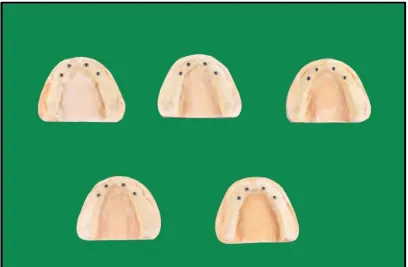
[image:59.595.112.520.315.582.2]
Fig:39 Measuring from implant replica 1 is taken as zero.
[image:61.595.171.461.362.718.2]RESULTS
The aim of present in vitro study was conducted to compare and evaluate the
positional accuracy of implants with different splinting materials using two different
elastomeric impression materials.
Twenty cast were made of which ten casts were obtained using pattern
resin splinting material, and VPS and VPES as impression material and ten casts
were obtained using BisGMA splinting material, VPS and VPES as impression
material. The samples were divided into four groups were comprising of five casts
each. The groups were designated as group I(A), II(A), I(B) & II(B).
Group I (A): Pattern resin as splinting material and VPS as impression
material were used.
Group II (A): Pattern resin as splinting material and VPES as impression
material were used.
Group I (B) : BisGMA as splinting material and VPS as impression material
were used.
Group II (B) : BisGMA as splinting material and VPES as impression material
were used.
The following results were obtained from the study which compared the inter
implant distances in x, y and z axis and the angular relationships of the implants to
horizontal plane in z axis using co-ordinate measuring machine. These four
parameters were compared between the reference model and test groups (Group I(A),
Group II(A), Group I(B) and Group II(B)). Mean and standard deviation (S.D) of all
the values for each group were obtained and they were statistically analysed by using
one way ANOVA and Post hoc test.
The following results were drawn from the study:
Table:1 to 16 Shows Basic Values, Mean And Standard Deviation Of Inter
Implant Distance In X-Axis, Y-Axis, Z-Axis and Implant Angulation for the Group I
(A),Group II (A),Group I (B),Group II (B) Samples (values in mm) and (Values in
Degree)
Table:17 to 20 Shows Difference in Inter-Implant distance in X-Axis,
Y-Axis, Axis (Values in mm) and Implant angulation to Horizontal Plane in
Z-Axis (Values in Degree)
Table: 21 to24Shows Comparison of Inter-Implant Distance in X-Axis,
Y-Axis, Axis (Values in mm) and Implant angulation to Horizontal Plane in
Z-Axis (Values in Degree
TABLE:1 BASIC VALUES, MEAN AND STANDARD DEVIATION OF INTER IMPLANT DISTANCE IN X-AXIS FOR THE GROUP I (A) SAMPLES.
SAMPLES 1 2 3 4 5 MEAN/SD
D1X(mm) 7.375 7.568 7.238 8.151 7.001 7.466/0.434 D2X(mm) 23.502 23.665 23.404 24.507 23.242 23.664/0.495 D3X(mm) 34.286 34.284 34.217 34.444 34.202 34.286/0.0958 INFERENCE:
D1X – distance between replica 1 and replica 2 in X-axis D2X – distance between replica 1 and replica 3 in X-axis D3X – distance between replica 1 and replica 4 in X-axis
For Group I (A) samples, the mean inter implant distance in x-axis, between replica 1
and replica 2 (D1X) is 7.466 mm, between replica 1 and replica 3 (D2X) is 23.664 mm and between replica 1 and replica 4 (D3X) is 34.286 mm.
TABLE:2 BASIC VALUES, MEAN AND STANDARD DEVIATION OF INTER IMPLANT DISTANCE IN Y-AXIS FOR THE GROUP I (A) SAMPLES.
SAMPLES 1 2 3 4 5 MEAN/SD
D1Y(mm) 9.072 8.618 9.258 8.116 9.299 8.872/0.501 D2Y(mm) 9.464 8.779 9.640 11.159 9.343 9.677/0.888 D3Y(mm) 1.498 0.840 2.372 2.278 1.498 1.129/2.104 INFERENCE:
D1Y – distance between replica 1 and replica 2 in Y-axis D2Y – distance between replica 1 and replica 3 in Y-axis D3Y – distance between replica 1 and replica 4 in Y-axis
For Group I (A) samples, the mean inter implant distance in Y-axis, between replica 1
and replica 2 (D1Y) is 8.872 mm, between replica 1 and replica 3 (D2Y) is 9.677 mm
and between replica 1 and replica 4 (D3Y) is 1.129 mm.