i
“ I hereby declare that I have read through this report entitle “Modelling and Analysis an Overcurrent Protection in Power System Network Using PSCAD” and found that it has comply the partial fulfillment for awarding the degree of Bachelor of Electrical
Engineering (Industrial Power)’
Signature : ……….
Supervisor’s Name : Dr. Mohd Hendra Bin Hairi………
ii
MODELLING AND ANALYSIS AN OVERCURRENT PROTECTION IN A POWER SYSTEM NETWROK USING PSCAD
MOHAMAD HISHAM BIN KHAIRUL MASRI
A report submitted in partial fulfillment of the requirements for the degree
of Electrical Engineering (Industrial Power)
Faculty of Electrical Engineering
UNIVERSITI TEKNIKAL MALAYSIA MELAKA
iii
I declare that this report entitle “Modelling and Analysis an Overcurrent Protection in Power System Network Using PSCAD” is the result of my own research except as cited in the references. The report has not been accepted for any degree and is not concurrently submitted in candidature of any other degree.
Signature : ………
Name : Mohamd Hisham Bin Khairul Masri …
iv
v
ACKNOWLEDGMENT
With the name of Allah the most gracious and the most merciful. The success and the final outcome of the project requires a lot of assistance and guidance from many people. Finally I am able to complete for my final year project entitled Modelling and Analysis an Overcurrent Protection in Power System Network Using PSCAD. I would like to express my gratitude to my respected supervisor Dr. Mohd Hendra Bin Hairi for his guidance, encouragement and valuable time throughout completing this project.
I would also like to thank all my lecturers and faculty for all the experiences and knowledge that I gained throughout my learning in Universiti Teknikal Malaysia Melaka (UTeM). Besides, all my friends whom involve directly or indirectly in this project.
vi
ABSTRACT
vii
ABSTRAK
viii
TABLE OF CONTENT
CHAPTER TITLE PAGE
SUPERVISOR DECLARATION i
PROJECT TITLE ii
DECLARATION iii
DEDICATION iv
ACKNOWLEDGEMENT v
ABSTRACT vi
ABSTRAK vii
TABLE OF CONTENT viii-xi LIST OF ABBREVATIONS xii
LIST OF TABLES xiii
LIST OF FIGURES xiv-xv LIST OF APPENDIX xvi
1 INTRODUCTION 1
1.1 Background 1
1.2 Problem Statement 2
1.3 Objectives 2
1.4 Scope of research 3
ix
2 LITERATURE REVIEW 4
2.1 Introduction 4
2.2 Fault type and effects 5
2.3 Overcurrent 6
2.4 Overcurrent Protection 6
2.5 Principles of Relay Operation 7
2.6 Overcurrent Relay 8
2.7 Classification of Over-Current Relays. 9 2.7.1 Instantaneous Overcurrent Relay. 10 2.7.2 Definite Time Overcurrent Relay. 10 2.7.3 Inverse Definite Minimum Time (IDMT) Overcurrent Relay. 10
2.8 IDMT Electromechanical Relay. 11
2.8.1 Mathematical Express. 12
2.9 Distributed Generation. 14
2.9.1 Protection issues in presence of DG units. 14
2.10 PSCAD 15
2.11 Summary 16
3 METHODOLOGY 17
3.1 Introduction 17
3.2 Flow Chart of Methodology 17
3.2.1 Design the circuit model 19
3.2.2 Apply the IDMT overcurrent relay to the protection scheme. 19 3.2.3 Apply fault in the circuit model. 19 3.2.4 Compare the relay operation time (ROT) between IDMT relay
x
3.2.5 Compare the ROT between IEC and IEEE curve standard 20 3.2.6 Compare the ROT before and after distributed generator (DG)
installation. 20
3.2.7 Data Analysis 20
3.3 Circuit Modelling 21
3.3.1 Circuit Components. 21
3.3.1.1 Three-Phase Voltage Source. 21
3.3.1.2 Transformer 22
3.3.1.3 Load 23
3.3.1.4 Measurement and Output Device. 24 3.3.1.5 Three phase fault logic. 25 3.3.1.6 Overcurrent relay. 25 3.3.2 Overcurrent relay modelling 26
3.3.2.1 Time-Dial Setting 27 3.3.2.2 Pickup-current setting. 27
3.3.3 Circuit Model. 29
3.3.4 Circuit analysis. 30
3.4 Summary 31
4 RESULT AND DISCUSSION. 32
4.1 Introduction. 32
4.2 Network Model. 32
4.3 Result & Discussion. 33
4.3.1 Various Type of Fault. 33
xi
4.3.1.4 Comparison Case 1, Case 2, and Case 3. 38
4.3.1.5 Conclusion. 38
4.3.2 Various Type of Relay Curve. 39 4.3.2.1 Comparison IDMT curve characteristic. 39 4.3.2.2 Comparison IEC 60255 & IEEE C37.112 Relay Curve
Standard 41
4.3.2.3 Conclusion. 42
4.3.3 Relay Operation With DG and Without DG Installation. 43
4.3.3.1 Network Model. 43
4.3.3.2 Relay Operation Time with DG and without DG. 44 4.3.3.3 Current Flow Study. 46
4.3.3.4 Conclusion. 49
4.4 Summary 50
5 CONCLUSION & RECOMMENDATION 51
5.1 Conclusion 51
5.2 Recommendation and Future Work 52
REFERENCE 53
xii
LIST OF ABBREVIATIONS
UTEM Universiti Teknikal Malaysia Melaka FKE Fakulti Kejuruteraan Elektrik
TNB Tenaga Nasional Berhad
IDMT Inverse Definite Minimum Time SLG Single-Line-to-Ground
DLG Double-Line-to-Ground TPG Three-Phase-to-Ground
IEEE Institute of Electrical and Electronic Engineer IEC International Electrotechnical Commission SI Standard Inverse
VI Very Inverse
EI Extremely Inverse
TDS Time Dial Setting
MV Mega Volt
xiii
LIST OF TABLES
TABLE TITLE PAGE
2.1 ANSI/IEEE and IEC constants for standard overcurrent relays. 13 3.1 a) Pickup current for normal circuit, b) Pickup current for 28
circuit with DG.
4.1 Relay Operation Time (ROT) at Phase A. 34
4.2 The Relay Operation Time (ROT) at Phase B. 36
4.3 Relay Operation Time (ROT) at Phase C. 37
4.4 Relay Operation Time (ROT) for IDMT Relay Curve 39 Characteristic.
4.5 Comparison relay model between curve characteristic. 40 4.6 Relay Operation Time (ROT) of IEEE C37.112 and IEC 60255. 42
4.7 Relay Operation with DG and Without DG. 44
xiv
LIST OF FIGURES
FIGURES TITLE PAGE
2.1 The condition of faults in three phase system. 5
2.3 The protective scheme logic operation. 7
2.4 Logical representation of Over-Current Relay. 8
2.5 IDMT Relay Mechanism. 9
2.6 Inverse Time Characteristic Curve 11
2.7 PSCAD software. 16
3.1 Flowchart of Methodology. 18
3.2 Three-phase voltage source. 22
3.3 3-Phase 2-Winding Transformer. 22
3.4 Load 23
3.5 Current Meter and output meter. 24
3.6 Three phase fault logic. 25
3.7 Overcurrent Relay. 25
3.8 Functional Block Diagram of an Overcurrent Relay. 26
3.9 Simulation model of MV distribution network. 29
3.10 Circuit model for analysis study. 30
xv
xvi
LIST OF APPENDIX
APPENDIX TITLE PAGE
A IEC 60255 TIME-CURRENT CURVE CHARACTERISTIC 57
B IEEE C37. 112 TIME-CURRENT CURVE CHARACTERISTIC 58
C SINGLE LINE DIAGRAM FOR TNB MV DISTRIBUTION 59
NETWORK.
D CURRENT RECORDED AT NORMAL CIRCUIT 60-61
1
CHAPTER 1
INTRODUCTION
1.1 Background
Power system protection is one of the branch in electrical power engineering. The protection term give a significant meaning in the electrical power engineering, where it is a division in electrical power engineering that concerned with the detection and isolations of fault and other type of unusual situation in power system. These fault often occur at the worst possible time and cause the maximum amount of inconvenient to the customer utility [11]. Thus the protection system is needed in providing the quick isolation of fault and faulty area from the service. This is to allow the largest possible part of the power system to continue in service.
There are several types of protection system that have been applied in the power system distribution by the utility company. The common protection system in distribution power system including distance protection, overcurrent protection and differential protection. This project focused on overcurrent protection scheme which is widely used in power system distribution for many years. Overcurrent protection system is use to detect the current magnitude which exceeds the specified adjustable current magnitude. This type of protection system is used with the overcurrent relay as the measuring instrument which it is respond to the current magnitude of the input current [1].
2
system in service. Besides, the impact of installation distributed generation (DG) into power system to the protection scheme also studied.
1.2 Problem Statement
Protection is one of the important element in the power system. A power system must not only capable of meeting the present load but also requires the flexibility to meet. The system must be kept in operation continuously without major breakdown [1]. A good protection scheme must achieve the basic features of protection system such as selectivity, stability, speed and sensitivity [4]. However, sometimes the relay that should be operated due to the fault does not work properly- delay in operation or does not function at all. It might be due to the problems from the setting of the relay or several condition. So, related to the problem, the study will be focused to performance of overcurrent relay based on relay operation time. Several cases were performed in order to investigate and study the relationship between relay operation times with the condition or event happened. The PSCAD is used as the platform to performed and demonstrate performance of the proposed overcurrent protection scheme under various scenarios [8].
1.3 Objectives
The objectives of this project are:
a) To model an overcurrent protection circuit in the power system network.
b) To analyze the relay operation time of overcurrent protection for the power system network based on type of relay characteristic curve, type of fault and their location.
3
1.4 Scope of research
This project totally focused on the overcurrent protection in distribution system. The circuit design involved five or less bus-bars and the power rating for the distributed generation is up to 10MW or less. The scopes for this research are specifically detailed as follows:
a) To analyze the effect of IDMT characteristic curve on relay operation time based on IEC 60255 and IEEE C37.112 standard.
b) Fault applied are three-phase-to-ground, double-phase-to-ground and single-phase to the ground.
c) To compare relay operating time between circuit without DG and circuit with DG installation.
d) The circuit modeled for distribution system of 132/33kV and 33/11kV. e) Analysis using PSCAD software.
1.5 Thesis Outline.
This thesis consists of five chapters which are introduction, literature review, methodology, result and conclusion. The first chapter had reviewed the objective and scope of this project with background of the study. Follow by chapter 2 which focused more on the theory and literature review of past research that relevant to the project, topic on overcurrent relay, IDMT relay curve characteristic and protection components have been focused in this chapter.
4
CHAPTER 2
LITERATURE REVIEW
2.1 Introduction
Electric power is generated and transmitted to the consumer through the large grid connection. The generation of electric power started from the power plant or generator, then the voltage will be step up before transmitting the electric power to the consumer. This practice is applied in order to minimize the losses of electric power through the transmission. The power is then transmitted to the commercial or residential consumers.
The main objective of all power system is to maintain and reliable power supply to the end user. In the normal condition, the power system will be works accordingly to the design. The current is distributed and flow in the pre-design value which suitable to the electrical power elements ratings. However, in some undesired condition the fault can be occurred. This conditions occur due to the natural event or human error such as weather, lightning, wind damage, human vandalism, insulation deterioration, falling tree and etc. This circumstances will lead to the unwanted situation where connection between phase conductor of transmission line and phase conductor to the ground happened.
5
2.2 Fault type and effects
Fault is a failure or unusual condition that experience by the power system where it comes from several condition including lightning and etc. Fault can be divided into two main areas, which are ‘Active’ and ‘Passive’ fault. [1]
The ‘Active’ fault happening when the actual current flow from one phase of conductor to the other phase of conductor which also known as phase-to-phase fault, or the flowing of current from one phase of conductor to the ground known as phase-to-ground. The active fault also can be divided into two other type of faults which are ‘solid’ fault and ‘incipient’ fault [1].
The ‘solid’ fault is happened as the result of immediate complete breakdown of insulation happen when the pick struck of cable or cable was dug up by bulldozer and etc [1]. These circumstances will lead to the very high of fault current where it can resulting to the explosion. Besides, the ‘incipient’ fault is a fault that start in a small way before it changes into catastrophic failure afterwards [1].
While for the ‘passive’ faults is actually not a real fault where it is a condition that are stressing the system beyond its design capacity. The typical example of passive fault such as over voltage, power swing, and under frequency. But this type of fault can ultimately change to active fault.
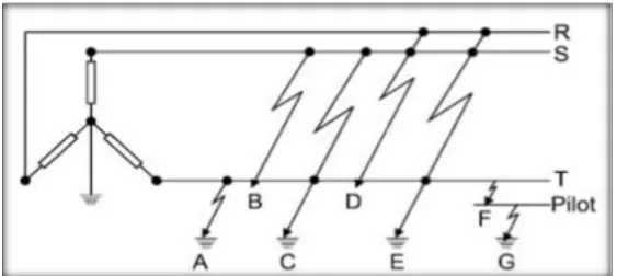
[image:21.595.164.446.597.723.2]Furthermore, there are several type of faults that can occur in a three-phase A.C. system where the power distribution system is globally a three-phase. The following figure shows the condition of faults that can occur in the three phase system.
6
(A)Phase-to-ground fault (B)Phase-to-phase fault
(C)Phase-to-phase-to-ground fault (D)Three-phase fault
(E)Three-phase-to-ground fault (F)Phase-to-pilot fault
(G)Pilot-to-ground fault
2.3 Overcurrent
Based on the National Electrical Code, the overcurrent is a phenomenon when the current of conductor or equipment is larger or excess than the equipment rating or the ampacity of a conductor. This situation may result from short circuit, ground fault or overload. [2]
Heat is always produce from the flowing of current in a conductor. The higher the current, the more the heat produced. Heat produced from the conductor can damage the electrical components if it is too high, which cause by the excessive current flow. For that reason, conductors have a rated continuous current carrying capacity or ampacity [2]. To protect the conductor from the excessive flow of current, the overcurrent protection devices are used. The protective devices are used to protect the circuit conductors from overheating by allow certain level of current to flow through it where it is should not higher than the rated current [2].
2.4 Overcurrent Protection
7
than the usual load current after the fault occurs. The overcurrent is divided into two subtypes which are instantaneous overcurrent and inverse-time overcurrent. The instantaneous overcurrent will operates instantaneously if the input current is larger than the setting value. For the inverse-time overcurrent it is operates in the way which the operating time is inversely with the input current [4].
2.5 Principles of Relay Operation
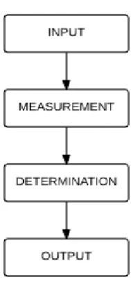
[image:23.595.257.352.522.729.2]There are a lot of different type of relays used in protective scheme. However, they are follow the same logic pattern. Figure 2.3 shows the protective scheme logic chart. There are inputs, measurement, determination and output. The input will represent current, voltage, frequency or perhaps other value that exist in protective circuit at any instant in time. The relay measures this values and then determines the circuit operating condition whether within in a normal parameters. Under normal operating condition output is zero which it is set to open or close contact at rest. However, in any intolerable fault level, the relay will imposes operating signal value under control circuit usually in terms of DC volt. This tripping signals is then fed into one or more circuit breaker to cause them to open, so as to isolate the faulty part from the rest of unfaulty power system.
8
2.6 Overcurrent Relay
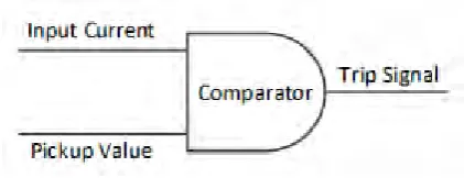
[image:24.595.199.410.352.433.2]An overcurrent relay provides protection against over currents. This type of relay uses current input from the CT and compare with the preset current. Figure 2.4 shows the logical representation of this type of relay. If the input current is exceeds the value of preset current the relay detects an overcurrent and send the trip signal to the circuit breaker which open its contact to disconnect the protected equipment [12]. When relay detects a fault, the condition is called fault pickup. In case the relay is instantaneous overcurrent relay the relay will issuing the trip signal to the breaker instantaneously after picking up the fault or it can delay for a specific time before send a trip signal to the breaker in case of time-overcurrent relay. This time delay is also known as the operation of the relay, and is computed by the relay on the basis of the protection algorithm incorporated in the microprocessor [19].
Figure 2.4: Logical representation of Over-Current Relay.
The overcurrent relay usually combine both instantaneous and time overcurrent units. Instantaneous response provided by moving armature units which functioning to operate on a very large currents. Time response is provided by the inverse induction disk unit and it is set to operate at a lower noise current.
Induction disc unit operates on the same principle as a motor. As in the figure 2.5, metal plate attached to the shaft can rotate freely. The coil current is specified. The eddy current is induced in the metal disc by magnetic field that generated by current. Then, the magnetic field of stationary coil interacts with the magnetic field of eddy current which generates a torque on the disc.