„‟I hereby declare that I have read through this report entitled “Modeling and Analysis of an Overcurrent Protection and Coordination in Power System Network using PSCAD Software” and found that it has complied the partial fulfillment for awarding the degree of
Bachelor of Electrical Engineering (Industrial Power)”
MODELING AND ANALYSIS OF AN OVERCURRENT PROTECTION AND COORDINATION IN POWER SYSTEM NETWORK USING PSCAD SOFTWARE
MUHAMMAD SHAFIQ BIN MUSLIM
A report submitted in partial fulfillment of the requirements for the degree of Electrical Engineering (Industrial Power)
Faculty of Electrical Engineering
UNIVERSITI TEKNIKAL MALAYSIA MELAKA
I declare that this report entitled “Modeling and Analysis of an Overcurrent Protection and Coordination in Power System Network using PSCAD Software” is the result of my own research except as cited in the references. The report has not been accepted for any degree and is not concurrently submitted in the candidate of any other degree.
DEDICATION
To my beloved father MUSLIM BIN NGADI
To my lovely mother RAFEAH BINTI JAJURI
Relatives and Siblings
ACKNOWLEDGEMENT
In the name of Allah S.W.T, the most gracious and merciful, praise to Allah the lord of universe and may blessing and peace of Allah be upon his messenger Muhammad S.A.W. First of all I would like to thank Allah for granting me the courage and health for the completion of this project report.
I would like to thank my supervisor Dr. Mohd Hendra Bin Hairi who taught me how to become a researcher. His professional behavior and excellent guidance in this project makes all the difficulties an easy one.
I have spent 3 months of my final year project in Power System Computer Aided Design Software (PSCAD) to complete my simulation. Mostly, thank Dr. Mohd Hendra Bin Hairi for very helpful to introduce and supervise me about PSCAD software.
During these 22 years of being a student, I have had many teachers who worked hard to educate me. I am aware of the great influence they have had on my life. I say thanks to all my teachers.
ABSTRACT
The case study in this project to analysis of an overcurrent protection and coordination in power system which is represent by using software of Power System Computer Aided Design (PSCAD). Protection against overcurrent by using coordination system benefits to protect the power system against any fault in order to limit the amount of duration during any interruption between breakers. To maintain high integrity of power system, this system could be minimizing damage in the system and components. Actually, faults may occur due to several reasons and they cannot be avoided such as lightning or other mechanical and natural causes.
ABSTRAK
Kajian dalam projek ini adalah untuk menganalisis sistem perlindungan lebihan arus dan koordinasi dalam sistem kuasa dengan menggunakan perisian Reka Bentuk Berbantukan Sistem Kuasa Komputer (perisian PSCAD). Perlindungan terhadap arus lebih manfaat dengan menggunakan sistem koordinasi untuk melindungi sistem kuasa terhadap apa-apa gangguan dan menghadkan jumlah tempoh masa gangguan antara pemutus. Untuk mengekalkan integriti yang tinggi sistem kuasa, sistem ini boleh mengurangkan kerosakan dalam sistem dan komponen. Sebenarnya, kesilapan boleh berlaku kerana beberapa sebab dan tidak boleh dielakkan seperti kilat atau sebab-sebab mekanikal dan semula jadi lain.
TABLE OF CONTENTS
CHAPTER TITLE PAGE
ACKNOWLEDGEMENT i
ABSTRACT ii
ABSTRAK iii
TABLE OF CONTENTS iv
LIST OF FIGURE viii
LIST OF TABLE xi
LIST OF GRAPH xii
1 INTRODUCTION 1
1.1 Introduction 1
1.2 Project Background 2
1.3 Problem Statement 3
1.4 Project Objectives 3
1.5 Scope 4
1.6 Expected Project Outcome 4
1.8 Report outline 5
2 LITERATURE REVIEW 6
2.1 Literature Review Overview 6
2.2 What Is Power System Protection 6
2.3 What Is Protection And Coordination 7
2.4 PSCAD Software 11
2.4.1 What Is PSCAD Software 11
2.4.2 Application of PSCAD Software 11
2.4.3 PSCAD Master Library 12
2.5 Faults Analysis Studies 13
2.6 Relay 15
2.6.1 Characteristics of Relay 16
2.6.2 Relay Speed 18
3 METHODOLOGY 23
3.1 Literature review 23
3.2 Collecting data 23
3.3 Design the simulation 24
3.3.1 Construct single line diagram 24
3.3.2 Transformer 26
3.3.3 RMS meter 27
3.3.4 Relay setting 28
3.4 Troubleshoot the simulation 33
3.5 Relay setting problem 33
3.6 Methodology flowchart 37
4 RESULT AND DISCUSSION 39
4.1 Introduction 39
4.2 Result and discussion 39
4.3 1st CASES 40
4.3.1 Time margin for protection coordination 40
4.3.2 Overcome supply interruption 44
4.3.3 Relay signal in different type of fault 45
4.4 2nd CASES 46
4.4.1 Time margin for protection coordination 46
4.4.2 Overcome supply interruption 50
4.4.3 Relay signal in different type of fault 51
4.5 3rd CASES 52
4.5.1 Time margin for protection coordination 52
4.5.2 Overcome supply interruption 56
4.5.3 Relay signal in different type of fault 57
4.6 4th CASES 58
4.6.1 Time margin for protection coordination 58
4.6.2 Overcome supply interruption 62
4.7 5th CASES 64
4.7.1 Time margin for protection coordination 64
4.7.2 Overcome supply interruption 68
4.7.3 Relay signal in different type of fault 69
4.8 6th CASES 70
4.8.1 Time margin for protection coordination 70
4.8.2 Overcome supply interruption 74
4.8.3 Relay signal in different type of fault 75
5 CONCLUSION AND RECOMMENDATION 76
5.1 Introduction 76
5.2 Conclusion 76
5.3 Future Recommendations 78
REFFERENCE 79
APPENDICES 81
Appendices A: Inverse Definite Minimum Time (IDMT)
82
Appendices B: Letter Of Confirmation From Tenaga Nasional Berhad
LIST OF FIGURE
FIGURE TITLE PAGE
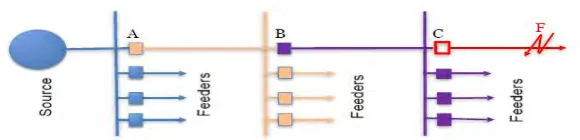
1.2.1 Coordination for Radial System 2
2.3.1 Time Versus Current Fuse to Fuse Coordination 8 2.3.2 Time Versus Current Auto-Recloser to Fuse Coordination 9 2.3.3 Time Versus Current Circuit Breaker to Fuse
Coordination
9
2.3.4 Time Versus Current Circuit Breaker to Fuse Coordination
10
2.3.5 Time Versus Current Circuit Breaker to Auto Recloser Coordination
10
2.4.1 Power System Computer Aided Design 11
2.4.2 Master Library in PSCAD 13
2.5.1 Example of Short Circuit 14
2.5.2 Unbalanced Fault 15
2.6.1 Three-Layer Structure of Power System 15
2.6.2 Reliability of Protection System 16
2.7.1 Time-Current Characteristics Of Definite Time (DT) And Inverse Definite Minimum Time (IDMT) Relay
19
2.7.2 Effect of Changing Plug Setting (PS) 21
2.7.3 Effects of Changing Time Multiplier Setting (TMS) 22 3.3.1 Single Line Diagram of Distribution System 25
3.3.2 Three Phase Two Winding Transformer 26
3.3.3 Transformer 1, T1 26
3.3.4 Multi-meter 27
3.3.5 Inverse Time of Overcurrent Relay for 3L5 and AR4003A 28 3.3.6 Inverse Time of Overcurrent Relay for 4L5 and AR4001A 29 3.3.7 Inverse Time of Overcurrent Relay for AR4001A and
ARJ100
29
3.3.8 Inverse Time of Overcurrent Relay for ARJ100 and ARJ1001
30
3.3.9 Inverse Time of Overcurrent Relay for ARJ101 and ARJ104
30
3.3.10 Inverse Time of Overcurrent Relay for AR J101 and AR 331
31
3.3.11 Three Phase Fault 31
3.3.12 Line-to-Ground 31
3.3.13 Double Line-to-Ground 31
3.3.14 Timed Fault Logic 32
3.3.15 Type of Fault 32
3.4.2 Relay setting for 4L5 and AR4001A 34 3.4.3 Relay setting for AR J100 and AR4001A 34 3.4.4 Relay setting for AR J101 AND AR J100 35 3.4.5 Relay setting for AR J104 and AR J101 35
3.4.6 Relay setting for AR 331 AND AR J101 36
3.5.1 Methodology Flowchart 38
4.3.1 Operation of Relay at AR4003B and 3L5 40
4.3.2 Case 1 Backup Supply Interruption 44
4.4.1 Operation of Relay at AR4001A and 4L5 46
4.4.2 Case 2 Backup Supply Interruptions 50
4.5.1 Operation of Relay at ARJ100 and AR4001A 52
4.5.2 Case 3 Backup Supply Interruptions 56
4.6.1 Operation of Relay at ARJ101and ARJ100 58
4.6.2 Case 4 Backup Supply Interruptions 62
4.7.1 Operation of Relay at ARJ104 and ARJ101 64
4.7.2 Case 5 Backup Supply Interruptions 68
4.8.1 Operation of Relay at AR331 and ARJ101 70
LIST OF TABLE
TABLE TITLE PAGE
2.7.1 Relay Characteristics to IEC 60255 20
LIST OF FIGURE
GRAPH TITLE PAGE
4.3.1 Fault current AR4003B and 3L5 41
4.3.2 Relay Operation Time Tripping for AR4003B 41 4.3.3 Relay Operation Time Tripping for 3L5 42
4.4.1 Fault current for AR4001A and 4L5 47
4.4.2 Relay Operation Time Tripping for AR4001A 47 4.4.3 Relay Operation Time Tripping for 4L5 48
4.5.1 Fault current for ARJ100 and AR4001A 53
4.5.2 Relay Operation Time Tripping for ARJ100 53 4.5.3 Relay Operation Time Tripping for AR4001A 54
4.6.1 Fault current for ARJ101 and ARJ100 59
4.6.2 Relay Operation Time Tripping for ARJ101 59 4.6.3 Relay Operation Time Tripping for ARJ100 60
4.7.1 Fault current for ARJ104 and ARJ101 65
CHAPTER 1
1
INTRODUCTION
1.1 Introduction
Major electrical power systems are generation, transmission, and distribution. From the generation of electricity, power supply will distribute through the transmission line. The transmission line will reach the distribution system to separate the power supply. In distribution system, there are including primary and secondary distribution system. This system runs the power supply from the substations going to the customer.
Protective relay is one of the components that very important in protection and coordination. These components give an advantage to reduce harmful damage to both electrical equipment and public when there have any interruption fault occur. The characteristics of relay design to get action as fast as possible when the fault current happens.
1.2 Project Background
The simple design of power system network should describe the real situation of power system flow. The value of power, voltage and current is given to fulfill the relation. The design also include fault to operate the function of circuit breaker. Three phase fault was applied because it was the worst fault and high current. The function of protection and coordination is to limit the duration during interruption or fault. This is because when fault happen, the transient of fault will cause damage of electrical equipment. To overcome this problem, time dial of relay must be small and probably fast action to trip.
[image:19.595.162.452.603.673.2]In electrical power system, fault happen when there have an abnormal current condition. For example, short circuits happen when the accidentals low resistance connection or current bypass through the normal load. There some interruption or failures that can cause the open-circuit fault happen. In three phase systems, fault can happen during phase or ground fault. There is only happen either phase fault or ground fault or both phase and ground fault. In power system, protective device was design to stop the faults when occur and protect the device from damage(Chen et al., 2012).
1.3 Problem Statement
Power system is the flow of power to supply electricity to customer. To give full of power supply to customer, there might be not have any disturbance or interruption in power transportation. Protection system is one of the most necessary ways to protect the transportation of power supply. During the transportation of power supply, there has much electrical equipment that influence in the system. The electrical components that influence in the system are transformer, buss bar, transmission line and etc. When an interruption occurs, the overcurrent will interrupt the electrical component. Each of the components has the limitation to support the overcurrent fault. Time is the most factors that can attach damage to the electrical element. The exposing of equipment to the interruption longer than usual time will take the equipment to damage.
In Overcurrent Protection and Coordination, there have many circuit breaker that will take action in one circuit which is „protective‟ circuit breaker and „protecting‟ circuit breaker. Protecting circuit breaker will take action first when fault happen. If protecting circuit breaker fail to isolate the fault, so it will affected the second circuit breaker. Now the damage taken during fault increasing to two damage circuit breaker. During this interruption, the disadvantage will effect to the customer. Customer will don‟t have any power supply until the maintenance complete by worker. Therefore, the maintenance cost will increase compare the damage of one circuit breaker than two circuit breaker that get damage.
1.4 Project Objectives
The objectives of this project are stated below:
1. Modeling a simulation of overcurrent protection and coordination power system network.
2. Reduce exposure and isolate problem.
1.5 Scope
In this project, there are some limitations are made:
Using Power System Computer Aided Protection (PSCAD) to design the power network.
Only use current transformer and Inverse Time Over Current (itoc51) as relay.
Overcurrent protection and coordination in distribution system.
Faults apply in three phase, double phase and single phase. Three phase fault is used as the worst fault.
The distribution system will discover in 132kV-33kV distribution system in Behrang.
There are some limitations during this project. First is to find the true information about generation, transmission line, distribution and circuit breaker. To get the trusted information, journal and IEEE standard is taken from the library and revision book. Next, this project will do only in a design by using PSCAD. There is no outside observation has been done. To analyze the correction of data inserted, calculation has been done to confirm the data input.
1.6 Expected Project Outcome
1.7 Significant of project
The research of signal in relay operation of overcurrent protection and coordination, there has a time margin between two signals of operation relay. The relay will operate when fault occur. To improving the protection coordination, the main system of tripping needs a backup system to flow the power supply through the customer.
1.8 Report outline
The main focus of this report was to discuss about the overcurrent protection and coordination system in distribution system. Modeling the simulation of protection coordination by using Power System Computer Aided Design (PSCAD) was used as a simulator in this report. This report will divide into five parts which are introduction, literature review, research methodology, results and conclusion.
CHAPTER 2
2
LITERATURE REVIEW
2.1 Literature review overview
This part discuss about the reviews and information data about protection and
coordination. The information data must be understood to complete the project. Every data and standard was collect from revision book, journals and world web.
2.2 What is Power System Protection?
Protection can be define as “the science, skill, and art of applying and settings relays or fuses to provide maximum sensitivity to faults and undesirable conditions, but to avoid their operation on all permissible or tolerable condition”-Blackburn(Durand, 2010).
[1]
Power system protection is used to protect power system against any fault in order to: i. Prevent danger and accident to public.
ii. Minimize damage to equipment. iii. Minimize supply disruption.
iv. Maintain high integrity of power system quality.
Power system protection works through detection of fault and subsequent isolation of the fault using relay combination with circuit breaker or fuse. With correct setting of relay and selection of fuse rating, proper fault isolation can be achieved.
Main function of protection system in electrical power system is to ensure the continuity of the electrical power supply. To fulfill this condition, protection device must be able to detect the abnormal current condition in electrical equipment or circuit. It does also can detect the location where the faults occur. To execute the isolate zone, protective device must have true decision to take action. Protection also can protect the other equipment from taking damage and can flow current depend on rating(Homburg, Power, Engineer, & Services, 2011). [2]
2.3 What is Protection and Coordination?
Protection and coordination is a protective device that can manage the best timing of tripping when interruption occurs. The main advantage is to minimize the total damage of electrical component(IEEE, 1997)[4]. Besides, it can increase the lifespan of the electrical component.