Available Online at www.ijergs.in
Volume - 5, Issue - 4, July – August - 2019, Page No. 10 - 22
10
Comparative Analysis of Power System Total Harmonics During Fault using Overcurrent Relay Implementing
Fuzzy Logic Controller
Ravindra Nath1, Department of Electrical Engineering, Arya Institute of Engineering & Technology, Jaipur, India
E-Mail Id : [email protected]
Deepak Sharma2, Department of Electrical Engineering, Arya Institute of Engineering & Technology, Jaipur
E-Mail id: [email protected]
Rajkumar Kaushik3, Asst. Professor, Department of Electrical Engineering, Arya Institute of Engineering & Technology,
Jaipur
E-Mail id: [email protected]
Abstract
To manage overcurrent, relay is used namely overcurrent relay and to optimize reactive power FACTS devices are in
trend. In this work, four-unit system is created and a fault is introduced for analysis. To manage reactive power
STATCOM is implemented. The reason to work with these traditional controllers is to optimization their performance
using latest technologies. Similarly, in this work overcurrent relay is optimized using additional trip mechanism and
STATCOM is optimized its performance using PID and Fuzzy logic controller (FLC). Comparative analysis is conducted
for PID and fuzzy logic controller for output results. Parameter considered for these comparisons is voltage, current,
Total harmonic distortion (THD), active power and reactive power.
The system is designed in MATLAB/ Simulink software with separate modelling of PID and Fuzzy logic controller.
Keyword: Over current Relay, FACTS, STATCOM, Fuzzy Logic Controller, THD
Introduction
Relays play an important role in protection of any electrical system. Relay prevents the system by separation from faulty
area / part so it can’t damage health area. Proper use of relay and its tuning gives a strong system and prevent from break
down. FACTS devices along with relay are best to increase the efficiency of power system.
Power System Structure
As shown in Fig. 1.1, a specific power system consists of generation units, transmission networks, distribution networks
and loads. Electric power is produced by the synchronous generator located in the power plants, which convert a primary
source of energy to electrical power. Generally, the generated voltage of power is running from 10kV to 25kV. This
voltage has then increased from 230kV to 765kV high voltage level through step-up transformer. After this, the electrical
power transmission on these high voltages is transmitted through the network. In the substation, the voltages run down to
the lower level. There, electric energy is distributed on the basis of the needs of the customers to load through primary
and secondary distribution feeders.
Overcurrent protection
e
11
e
11
e11
e
11
e11
e
11
e11
e
11
e11
e
11
e
11
e
11
e
11
e11
e
11
e11
e
11
e11
e
11
e11
e
11
operated when the stream exceeds the threshold. Both transient and time-delayed trips are common. Overcurrent
protection is simple, cheap and reliable. Although it performs best in the radial system because the selection system is
difficult or sometimes it is impossible to obtain in fake system configuration.
Short Circuit Overcurrent Protection
Normally, during the event of a mistake, there is a considerable increase in the normal operation in respect of normal
operation. This behavior is used by short circuit overcurrent protection so that the operation of the fault can be separated
from normal operation.
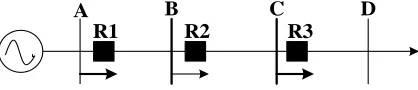
A B C D
R1 R2 R3
Fig. 1. A Radial Fed System Equipped with Non-Directional Overcurrent Protection.
In Figure 1, a radial fade system is shown where each line section is equipped with a non-directional overcurrent relay. In
order to achieve proper operation, each relay should be given an operation current, which is larger than the largest
possible surcharge, obviously the operation current should be less than the smallest possible fault current. To calculate
the smallest possible mistake, a phase-to-phase fault in the current stage is usually applied to the remote terminal for the
shortest possible short circuit power in the feeding terminal. To achieve selectivity, a high operational value relay is
given closer to the source where the relay is located. Typically, selectivity cannot be achieved exclusively by current
settings. To ensure satisfactory selectivity, a certain time delay is given to the relay. Generally, the relay in the busiest
distance is operated immediately, whereas the time delay for feeder near the feeder increases.
Fig. 2. Overcurrent Device Coordination for the Relays
In case of lattice system configurations, it may be impossible to give overcurrent protection settings as discussed above,
which provides a selective security system. Therefore, the overcurrent unit which is specially based on the current
magnitude, is complemented by a directional element. The name of this application is usually "Directional overcurrent
protection". Often fixed overcurrent relay relays are replaced by an inverse-time feature as shown in 2. With the delayed
time of the inverse time, the time of increasing relay increases with increasing time. Therefore, a large fault current will
be tripped faster than a small fault current. An inverse-time overcrowd relay enables the combination of short-circuit
protection and overload protection in the same device.
Statcom (Static Synchronous Compensator)
The first SVC with the voltage source converter, which was known as the situation in 1999, has the basic features of
12
12
12
12
12
12
12
12
12
12
12
12
12
12
12
12
12
12
12
12
12
than the synchronous condenser.In many ways, there is better mobility in it, along with less cost of maintenance, along
with investment costs and operating costs also decreases. The operating structure and basic structure of STATCOM is
shown in Figure 3. Where V is the voltage and I have the source current.
The reactive power is completely independent from the actual generated voltage at the connection point; This is the main
advantage of STATCOM, due to which STATCOM maintains its full potential at the most critical contingencies, the use
of voltage source converters for grid interconnection in today's distributed energy field is common. The combination of
energy storage on the DC-side of the converter is the next step of STATCOM development. [2-3]
Fig.3. STATCOM structure and voltage / current characteristic
Fuzzy Logic Controller (Optimization Techniques)
Fuzzy control takes an advantage of fuzzy set theory to state a non-linear controller that was first developed by Mamdani
in 1975.
A fuzzy controller has three components:
1. A fuzzyfier,
2. A rule base and
3. A de-fuzzyfier.
The inputs given to the controller are numbers and the outputs are also the numbers, but all complications inside the
controller is done with the help of fuzzy variables. The first step is preceded by transforming the crisp inputs to
memberships of each fuzzy set defined for the inputs. This operation is called fuzzyfication and the block which is
responsible for this operation is called a fuzzyfier. These membership functions are used in the rule base that co-relates
fuzzy values of the given inputs to the output of the rule base. The output of the rule base is also a set of membership
tools of the fuzzy sets those known for the variables of the output. The fuzzy variable requires to be converted back to a
perfect number in order to interface with the physical world. This process is perfected by the Defuzzyfier.
Design And Implementation
Over current replay is designed for four generating sources. The system is controlled using relay and a STATCOM device
for reactive power. Modeling of system is designed in MATLAB / Simulink. Voltage source of 735 mw each is
e
13
e
13
e13
e
13
e13
e
13
e13
e
13
e13
e
13
e
13
e
13
e
13
e13
e
13
e13
e
13
e13
e
13
e13
e
13
and the result in the form of waveform and analysis is performed using controller of Fuzzy Logic at STATCOM terminals
and represented in next chapter of thesis.
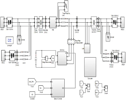
The implementation of proposed system in MATLAB / Simulink. This system is designed with four area voltage source
of 735 MW each connected with transmission line. Load of 200MW each is connected before fault, near to sending point
after load. As represented for controlling reactive power STATCOM is used with its controlling system.
Fig. 4.MATLAB Model for proposed system.
Fig. 5. MATLAB diagram of overcurrent relay in system.
14
14
14
14
14
14
14
14
14
14
14
14
14
14
14
14
14
14
14
14
14
Implementation of overcurrent relay with breaker is shown in figure 6 with bus A and Bus B. over current relay reacts to
the fault occur at 0.04 Ts and disconnects the system for protection. The relay is tuned at 50% TPS that reacts with the
current value reactive from line. Instantaneous overcurrent relay works for the system at current parameter rating exceeds
then rated current line seviour fault occur due to lightening etc.
STATCOM is used to control reactive power generated in line. As show in figure 7 it is designed in MATLAB / Simulink
with semi controller devices.
Fig.7. MATLAB model for STATCOM Controller.
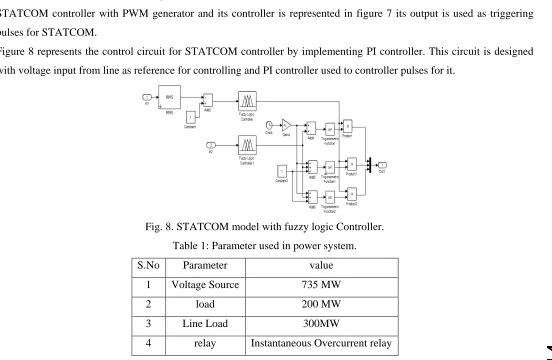
STATCOM controller with PWM generator and its controller is represented in figure 7 its output is used as triggering
pulses for STATCOM.
Figure 8 represents the control circuit for STATCOM controller by implementing PI controller. This circuit is designed
with voltage input from line as reference for controlling and PI controller used to controller pulses for it.
Fig. 8. STATCOM model with fuzzy logic Controller.
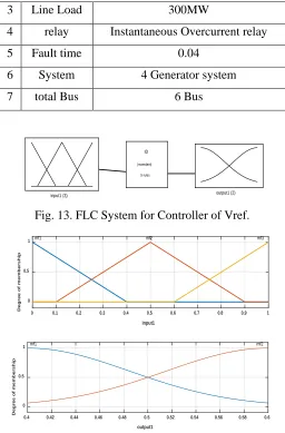
Table 1: Parameter used in power system.
S.No Parameter value
1 Voltage Source 735 MW
2 load 200 MW
3 Line Load 300MW
e
15
e
15
e15
e
15
e15
e
15
e15
e
15
e15
e
15
e15
e15
e15
e15
e
15
e15
e
15
e15
e
15
e15
e
15
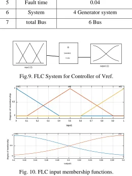
5 Fault time 0.04
6 System 4 Generator system
7 total Bus 6 Bus
input1 (3) output1 (2) ID
(mamdani)
5 rules
Fig.9. FLC System for Controller of Vref.
0 0.1 0.2 0.3 0.4 0.5 0.6 0.7 0.8 0.9 1
input1 0
0.5 1
Degree of membership
mf1 mf2 mf3
0.4 0.42 0.44 0.46 0.48 0.5 0.52 0.54 0.56 0.58 0.6
output1 0
0.5 1
Degree of membership
mf1 mf2
Fig. 10. FLC input membership functions.
input1 (3) output1 (2)
IQ (mamdani)
4 rules
Fig. 11. FLC System for Controller for Vdc.
Results And Analysis
Power system is designed in MATLAB/Simulink software. Overcurrent relay is used to trip system in case of fault. Fault
is injected in the system to analysis of parameter performance. STATCOM is connected to control reactive power in
system and manage distortions. For better performance PID and Fuzzy logic controllers(FLC) are compared and analysis
is performed in the form of waveforms shown in this chapter. Overall results represent better performance of FLC with
parameters as bus voltage and current, Total Harmonic Distortion (THD) and active & reactive powers in the system.
0 1000 2000 3000 4000 5000 6000 7000 8000 9000 10000
Time -20 -15 -10 -5 0 5 10 15 20 Voltage
16
16
16
16
16
16
16
16
16
16
16
16
16
16
16
16
16
16
16
16
16
3 Line Load 300MW
4 relay Instantaneous Overcurrent relay
5 Fault time 0.04
6 System 4 Generator system
7 total Bus 6 Bus
input1 (3) output1 (2) ID
(mamdani)
5 rules
Fig. 13. FLC System for Controller of Vref.
0 0.1 0.2 0.3 0.4 0.5 0.6 0.7 0.8 0.9 1
input1 0
0.5 1
Degree of membership
mf1 mf2 mf3
0.4 0.42 0.44 0.46 0.48 0.5 0.52 0.54 0.56 0.58 0.6
output1 0
0.5 1
Degree of membership
mf1 mf2
Fig. 14. FLC input membership functions.
input1 (3) output1 (2)
IQ (mamdani)
4 rules
Fig. 15. FLC System for Controller for Vdc.
Results and Analysis
Power system is designed in MATLAB/Simulink software. Overcurrent relay is used to trip system in case of fault. Fault
is injected in the system to analysis of parameter performance. STATCOM is connected to control reactive power in
system and manage distortions. For better performance PID and Fuzzy logic controllers(FLC) are compared and analysis
is performed in the form of waveforms shown in this chapter. Overall results represent better performance of FLC with
e
17
e
17
e17
e
17
e17
e
17
e17
e
17
e17
e
17
e17
e17
e17
e17
e
17
e17
e
17
e17
e
17
e17
e
17
0 1000 2000 3000 4000 5000 6000 7000 8000 9000 10000
Time -20 -15 -10 -5 0 5 10 15 20 Voltage
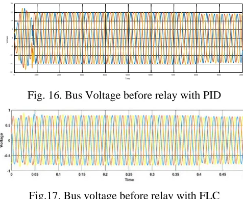
Fig. 16. Bus Voltage before relay with PID
Fig.17. Bus voltage before relay with FLC
Figure 14 & figure 15 represented the bus voltage of bus before relay with PID and FLC respectively it shows that the
voltage in PID circuit is not controlled by rating as compared with circuit connected with Fuzzy Logic Controller. FLC
used with STATCOM also controls the voltage Parameter in power system.
0 1000 2000 3000 4000 5000 6000 7000 8000 9000 10000 Time -25 -20 -15 -10 -5 0 5 10 15 20 25 Voltage
Fig. 18. Bus voltage after relay with PID
Fig. 19. Bus voltage after relay with FLC
Figure 16 & Figure 17 represented bus voltage of bus connected after relay with PID and Fuzzy Logic Controller
respectively. These waveform shows the control of voltage and relay operation after fault condition. As in PID there is
leakage in voltage where as in FLC the voltage is completely cutoff as relay is operating condition. Overcurrent relay
oprates at 0.05 μs in FLC.
0 1000 2000 3000 4000 5000 6000 7000 8000 9000 10000
Time -6000 -4000 -2000 0 2000 4000 6000 Current
18
18
18
18
18
18
18
18
18
18
18
18
18
18
18
18
18
18
18
18
18
Fig. 21. Current in bus before relay with FLC
Figure 18 & figure 19 shows current parameter of bus connected before over current relay and fault with PID and FLC
respectively. This shows that with PID the current gets zero before relay conditions, due to fault but in condition of FLC
it will remain in normal condition as the fault occur after this bus. So FLC is working more effectively in the System.
0 1000 2000 3000 4000 5000 6000 7000 8000 9000 10000
Time
-400 -300 -200 -100 0 100 200 300 400
Current
Fig. 22. Bus current after relay in PID
Fig. 23. Bus current after relay in FLC
Working condition of bus current in case of PID & FLC is represented in fig. 20 & fig. 21 respectively. It shows that
there is leakage current in case of PID where in FLC it is controlled.
Fig. 24. THD in bus voltage before relay in PID
e
19
e
19
e19
e
19
e19
e
19
e19
e
19
e19
e
19
e
19
e
19
e
19
e19
e
19
e19
e
19
e19
e
19
e19
e
19
Total harmonics Distortions (THD) in bus voltage connected before relay and fault is shown in figure 22 & figure 23. It
shows that with PID level of distortions is high whereas with FLC it is almost zero.
Fig. 26. THD in bus voltage after relay in PID
Fig. 27. THD in bus voltage after relay in FLC
Total harmonics Distortions (THD) in bus voltage connected before relay and fault is shown in figure 24& figure 25. It
shows that with PID level of distortions is high whereas with FLC it is almost zero.
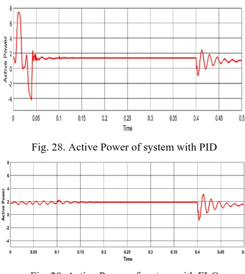
Fig. 28. Active Power of system with PID
Fig. 29. Active Power of system with FLC
Active power of system is represented in figure 26 & figure 27 with PID and FLC respectively. These waveform shows
that with PID there is variation at system output power whereas with FLC this variation is negligible. So working of FLC
20
20
20
20
20
20
20
20
20
20
20
20
20
20
20
20
20
20
20
20
20
Fig. 30. Reactive Power of system with PID
Fig. 31. Reactive Power of system with FLC
As shown in figure 28 & figure 29, reactive power of system with PID and FLC respectively. The waveform shows that
with FLC there is decreased in distortions as compared with PID system.
Conclusion
The proposed system is designed for analysis of overcurrent relay and STATCOM for micro grid system with four units.
System that is designed in MATLAB/ Simulink is using PID and fuzzy logic controller for optimization of reactive power
and working of overcurrent relay in case of fault.
Overview of system is presented in chapter-4 with mathematical modelling and its analysis using comparison of PID and
FLC is in chapter-5 with waveforms. The overall analysis of proposed system shows that fuzzy logic controller is more
optimized as compared to PID.
While using PID controller relay works with either buses connected to and fro where it contains harmonics in its output.
Similarly, on other hand fuzzy logic controller works for that bus where fault occurs and it controls active and reactive
power also in optimized conditions.
References
1. H. M. Sharaf, H. H. Zeineldin and E. El-Saadany, "Protection Coordination for Microgrids With Grid-Connected and
Islanded Capabilities Using Communication Assisted Dual Setting Directional Overcurrent Relays," in IEEE
Transactions on Smart Grid, vol. 9, no. 1, pp. 143-151, Jan. 2018.
2. Y. Yuanbo, X. Min, H. Taigui, W. Wei and C. Xiaodong, "Research on Condition-Based Maintenance in Relay
Protection," 2017 4th International Conference on Information Science and Control Engineering (ICISCE),
Changsha, 2017, pp. 1627-1631.
3. S. Makhzani, M. Zarghami, B. Falahati and M. Vaziri, "Hardware-in-the-loop testing of protection relays in
distribution feeders with high penetration of DGs," 2017 North American Power Symposium (NAPS), Morgantown,
e
21
e
21
e21
e
21
e21
e
21
e21
e
21
e21
e
21
e
21
e
21
e
21
e21
e
21
e21
e
21
e21
e
21
e21
e
21
4. K. Narendra, R. Midence, A. Oliveira, N. Perera and N. Zhang, "Commissioning process and acceptance test of a
sub-harmonic protection relay," 2017 70th Annual Conference for Protective Relay Engineers (CPRE), College
Station, TX, 2017, pp. 1-13.
5. E. Patrashkin and A. Andreev, "IEC-61850 use in central relay protection and automation network systems," 2017
International Conference on Industrial Engineering, Applications and Manufacturing (ICIEAM), St. Petersburg,
2017, pp. 1-5.
6. S. T. P. Srinivas and K. S. Swarup, "Optimal relay coordination and communication based protection for
microgrid," 2017 IEEE Region 10 Symposium (TENSYMP), Cochin, 2017, pp. 1-5.
7. H. F. Xiao, Z. Fang, D. Xu, B. Venkatesh and B. Singh, "Anti-Islanding Protection Relay for Medium Voltage Feeder
With Multiple Distributed Generators," in IEEE Transactions on Industrial Electronics, vol. 64, no. 10, pp.
7874-7885, Oct. 2017.
8. M. Išlić, A. Marušić and J. Havelka, "Distance protection relays installation prioritization in distribution networks
using analytic hierarchy process and cost-benefit analysis," 2017 25th Mediterranean Conference on Control and
Automation (MED), Valletta, 2017, pp. 534-540.
9. C. C. Teixeira and H. Leite, "The influence of a VSC based HVDC link on distance protection relay assessed by
CAPE software," 2017 IEEE Manchester PowerTech, Manchester, 2017, pp. 1-4.
10. E. L. Kokorin and S. A. Dmitriev, "Relay protection and automation equipment operability evaluation on the basis of
the graph probabilistic model," 2017 XX IEEE International Conference on Soft Computing and Measurements
(SCM), St. Petersburg, 2017, pp. 315-318.
11. M. Abdi-Khorsand and V. Vittal, "Modeling Protection Systems in Time-Domain Simulations: A New Method to
Detect Mis-Operating Relays for Unstable Power Swings," in IEEE Transactions on Power Systems, vol. 32, no. 4,
pp. 2790-2798, July 2017.
12. O. Liura, I. Sabadash, N. Vozna and I. Ostrovka, "Project of structural solutions and components of special processor
of relay protection in high-voltage lines of electricity transmission," 2017 XIIIth International Conference on
Perspective Technologies and Methods in MEMS Design (MEMSTECH), Lviv, 2017, pp. 70-73.
13. H. Zhan et al., "Relay Protection Coordination Integrated Optimal Placement and Sizing of Distributed Generation
Sources in Distribution Networks," in IEEE Transactions on Smart Grid, vol. 7, no. 1, pp. 55-65, Jan. 2016.
14. D. K. Singh, A. K. Singh and S. R. Mohanty, "An adaptive transmission line protection and modelling of numerical
distance relay with analog antialiasing filter," 2017 IEEE International Conference on Industrial Technology (ICIT),
Toronto, ON, 2017, pp. 388-393.
15. B. Vandiver, "Why testing digital relays are becoming so difficult! Part 3 advanced feeder protection," 2016 69th
Annual Conference for Protective Relay Engineers (CPRE), College Station, TX, 2016, pp. 1-6.
16. C. Pritchard, D. Costello and K. Zimmerman, "Moving the focus from relay element testing to protection system
22
22
22
22
22
22
22
22
22
22
22
22
22
22
22
22
22
22
22
22
22
17. N. Lizunov, R. S. Misbakhov and I. Z. Bagautdinov, "The centralized system of relay protection and automation for
substations of medium voltage," 2016 2nd International Conference on Industrial Engineering, Applications and
Manufacturing (ICIEAM), Chelyabinsk, 2016, pp. 1-6.
18. P. S. Kireev and S. V. Sarry, "Mathematical and physical modeling of arc transient resistance for relay protection
operating estimation," 2016 2nd International Conference on Industrial Engineering, Applications and
Manufacturing (ICIEAM), Chelyabinsk, 2016, pp. 1-4.
19. D. K. Singh, A. K. Singh, S. R. Mohanty and N. K. Singh, "Wind power generation by PMSG and fault protection
using over-current and differential frequency relay," 2016 IEEE Region 10 Humanitarian Technology Conference
(R10-HTC), Agra, 2016, pp. 1-6.
20. M. V. Andreev, Y. S. Borovikov and N. Y. Ruban, "Study of impact of relay protections operation on transients in
electric power systems using mathematical simulation," 2016 11th International Forum on Strategic Technology
(IFOST), Novosibirsk, 2016, pp. 187-190.
21. Z. Chen, Y. Zheng and Y. Liu, "Research of relay protection automatic testing technology for smart substation," 2016
International Conference on Smart Grid and Clean Energy Technologies (ICSGCE), Chengdu, 2016, pp. 19-23.
22. Jiang Chen, Junfang Wang, Yutao Song, Hao Xu, Guangjun Gong and Zhijun Chen, "Dynamic reliability quantitative
assessment of the relay protection system," 2016 IEEE International Conference on Power and Renewable Energy
(ICPRE), Shanghai, 2016, pp. 314-318.
23. M. A. Chowdhury, K. T. Reza, M. D. Alam and E. Basher, "Third harmonic differential over current relay based
protection system for stator ground fault in synchronous generator," 2016 9th International Conference on Electrical
and Computer Engineering (ICECE), Dhaka, 2016, pp. 606-609.
24. Y. Ateş and A. R. Boynueğri, "Adaptive protection and relay coordination approaches for next generation electricity
networks," 2016 National Conference on Electrical, Electronics and Biomedical Engineering (ELECO), Bursa, 2016,
pp. 43-47.
25. M. Sun, H. Wang and X. Zhu, "Fault characteristics of photolvoltaic power station and its influence on relay
protection of transmission line," 5th IET International Conference on Renewable Power Generation (RPG) 2016,