Article
An Integrated Pedal Follower and Torque Based
Approach for Electronic Throttle Control in a
Motorcycle Engine
Ashok B.
1,a, Denis Ashok S.
1,b,*
, and Ramesh Kumar C.
1,cSchool of Mechanical Engineering, VIT University, Vellore, Tamil Nadu 632 014, India
E-mail: a[email protected], b[email protected] (Corresponding author), c[email protected]
Abstract. Nowadays, electronic throttle control system is widely adapted in the motorcycle for better drivability, fuel economy and reduces the emissions. In such systems, pedal follower or torque based approach are used for calculating the required throttle angle for the given torque demand by driver. This work presents a throttle control system for the precise estimation of throttle angle based on the integrated pedal follower and torque based approach for the given accelerator position and torque demand by the driver. A mathematical model for an electronic throttle body is developed to understand the effects of nonlinearities due to friction and limp home dual springs. A PID controller with compensators are developed to handle the nonlinearities due to the friction and limp home dual springs in the proposed electronic throttle control system. A simulation study has been carried out using software in loop and hardware in loop simulation approaches for step, sinusoidal, and ramp input signals. The responses of electronic throttle body for opening the throttle angle and error are analyzed for the given input signals. The simulation result shows that the proposed compensators has significant advantage in reducing the throttle angle error and gives the desired output.
Keywords: Throttle angle estimation, electronic throttle control, throttle angle, compensators, limp home, friction.
ENGINEERING JOURNAL Volume 21 Issue 1
1.
Introduction
In recent years, electronic throttle body is widely preferred to control the air intake for regulating the engine torque in order to meet the performance and emission requirements of motorcycles. This system is gradually increasing in the modern motorcycles in order to provide a multiple technical benefits such as better vehicle response, high performance in terms of improving the fuel economy and trim down the emissions. In addition also for adapting with other system such as catalyst heating, cruise control, traction control, etc [1-5]. A typical electronic throttle body (ETB) is a mechatronic device which consists of a butterfly valve operated by a DC servo motor through a set of gear arrangements, a dual return spring in order to place the valve in LH (Limp Home) position, a redundant position sensor to measure the actual angle of throttle valve for the feedback [6-9]. Based on the driver requirements, the throttle angle has to be precisely maintained in order to obtain the better throttle response and drivability [10]. However, the presence of nonlinearities in the system, such as friction and limp-home position affects the position accuracy of the throttle valve.
Control system design of electronic throttle body for motorcycle engine is proposed by very few researchers. Panzani et al. proposed an adaptive control for the electronic throttle control for a sports bike. A hybrid feedforward–feedback friction compensator is introduced along with a PID controller to tackle the nonlinearity caused by the friction effects in the throttle body [11, 12]. Matteo et al. developed gain scheduler controller for ride by wire motorcycle application. A model-based gain-scheduled position control system for throttle position tracking has been proposed by means of linear parameter varying (LPV) method the stability of the closed-loop system is well proved [13, 14, 28]. Also a sliding mode throttle control for the motorcycle is proposed by Beghi et al. to deal with the nonlinearity caused by friction in the system. In order to avoid the electromechanical system modeling complexities, a state observer is proposed to estimate the states of the system. Then the estimated values are fed as input to the discrete-time sliding mode controller with integral action and by means of this controller the friction nonlinearity in the system is dealt [15, 16]. Also many of the electronic throttle control system related works are carried in the automobile related aspects. Chang Yang has developed a model based electronic throttle control with an added friction shaker to deal with the nonlinear effects caused by the friction alone. They found that the behavior and response time matches very well with theoretical analysis [17]. Andreas and Lars proposed a control system using the two concurrently active compensators to counter the nonlinear effects and approximately makes the system linear along with a PID controller [18]. Danijel et al. has developed an adaptive strategy consists of auto-tuning and self-tuning algorithms. The auto-tuner provides desired control performance, regardless of variations in electronic throttle body parameters due to production deviations, external conditions variations, and effects on aging also. Self-tuning strategy deals with process parameter variations which occur during a single engine run [19, 20]. Also the control systems developments by some of researches have focused to deal with the electronic throttle nonlinearities, based on neural network [21, 22] and fuzzy logic [23].
This work features the design of position control system for the throttle valve based on the drivers torque demand for a 305cc SI engine using a Bosch ETB. Within this context, this work focus on the design of the control system for throttle angle estimation based on the drivers torque demand and positioning the throttle valve by considering the nonlinearities such as friction and limp home return spring in the electronic throttle body for a motorcycle engine is developed. The proposed work is organized in following sections. Section 2 deals with the modeling of electronic throttle body to understand the behavior of the system. In section 3 the proposed control logic for the throttle angle estimation and throttle control system are discussed. While section 4, discuss the simulation and experimental results for the proposed strategy.
2.
Electronic Throttle Body (ETB) Modeling
Precise positioning of the throttle valve is important for regulating the airflow and torque requirements of the engine. However, there is variation in the actual position of the throttle valve as compared to desired throttle angle input due to the nonlinearities such as friction and limp home position in the system. In order to study the nonlinear effects on the angular position of throttle, an integrated model has been developed in the present work and it is explained in the subsequent sections.
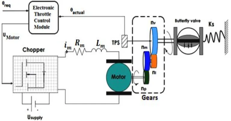
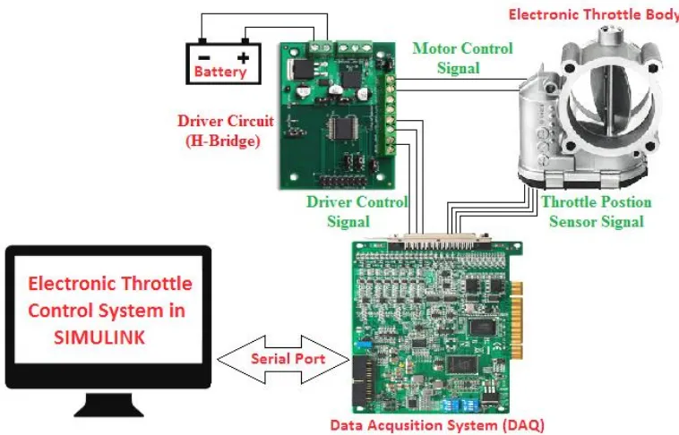
Fig. 1. Schematic of electronic throttle body system components.
Figure 1 shows a typical electronic throttle body consisting of DC servo motor, gearbox and dual no-return spring. For the desired throttle angle input ( , the throttle control system provides a motor voltage (UMotor) signal to the H-Bridge driver circuit.For actuating the motor, H-bridge creates a motor
armature current with an equivalent direction and duty cycle. In order to reduce the position error of the throttle valve a closed loop feedback control system is accomplished by using a throttle position sensor signal [29-34].
2.1. Modeling of DC Motor
The precise positioning of the throttle valve angle is changed by using the DC motor and it consists of an inductor, resistor and a back emf voltage due to the motor rotation is given as in Eq. (1).
*
m
motor m m m backemf motor
di
U R i L K W
dt
[image:3.595.126.510.308.509.2]2.2. Gear Arrangements
The butterfly valve is linked to the motor by means of the gear arrangements as shown in Fig. 1. The gear set consist of pinion gear(np), motor gear(nm), an intermediate gear(ni) and valve gear(nv). The equation for
the gear ratio (Gr) between the motor shaft and throttle plate is give as in Eq. (2),
*
motor v m
r
throttle i p
W n n
G
W n n
(2)
By substituting Eq. (2) and Kbackemf Kbackemf *Gr
*
m
backemf
motor m m m throttle
di
U R i L K W
dt
(3)
2.3. Limp Home Position Spring Model
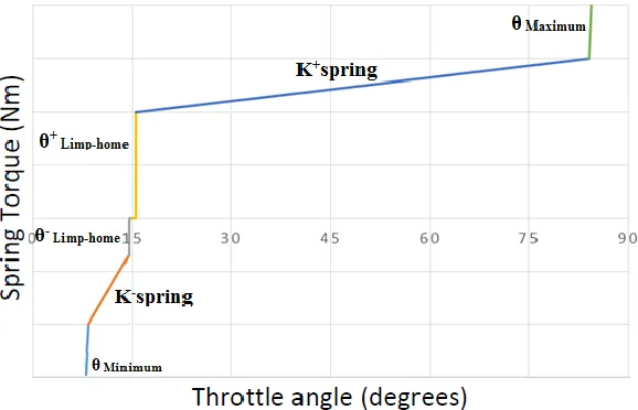
Electronic throttle body has two inbuilt springs to keep the throttle valve open at a default position in the event of malfunction in the electronic throttle or other systems. Each spring is acting independently on its respective direction, and both are pre-compressed. The throttle body used for this work has the spring balance point or the limp home position which varies between 14.5° (θ-Limp-home) and 15.5° (θ+Limp-home). This variation in limp positive and negative is due to the construction flaws in the throttle body, aging, etc. Their mean position is assumed as limp-home position (i.e. 15°). The mean position of the throttle plate was called as limp home region which is the fail safe location. The positions of limp home, maximum and minimum angle for the throttle body are varied for the different category of engine throttle bodies according to the requirements [33].
Fig. 2. Variation of spring torque with the throttle angle.
[image:4.595.154.443.427.613.2]( )
2 * ( )
2 * ( )
(
pre load spring throttle Limp throttle Limp
pre load Limp throttle Limp throttle Limp
spring
pre load throttle Limp Limp throttle Limp
pre load spring throttle
T K if
T if T T if T K
Limp) ifLimp throttle
(4)
2.4. Friction Model
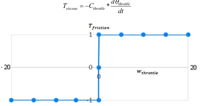
As the throttle valve moved by the servo motor, it has to overcome frictional forces created by the gearbox and as well as in the throttle valve which act as a nonlinear phenomenon in the system. The frictional forces create a frictional torque (Tstatic friction) which opposes the direction of the motion. For the modeling of
throttle body system, dry (Coulomb) friction and viscous friction are considered. A signum function is used to assess the direction of frictional torque depending on the direction of angular velocity. The signum function given as in Eq. (5),
( ) [ 1 1,0 0, 1 1]
sign x for x for x for x (5)
As there are two different springs are acting in their respective active region, direction of friction is dependent on the direction of motion. Thus the frictional torque acting upon the system is related to the throttle movement direction (i.e. sign of velocity of throttle plate movement) as shown in Fig. 3. This condition is included by using signum function and the static frictional torque is modeled using coulomb friction which is represented as in Eq. (6),
* ( )
static coulomb throttle
T T sign W (6)
Another friction factor is the viscous friction and is directly proportional to the throttle angular velocity. Its direction is always opposite to movement. Hence torque due to viscous friction is given as in Eq. (7), * throttle viscous throttle d T C dt
(7)
Fig. 3. Variation of frictional torque with throttle angular velocity.
2.5. Dynamic Motion of Electronic Throttle Body
[image:5.595.137.463.466.639.2]. throttle
motor motor motor motor motor motor motor
r
T
T K i J W C W
G
(8)
Behavior of the throttle valve load torque, which is transmitted through the reduction of gear trains, is governed as follows in Eq. (9),
throttle throttle throttle throttle throttle spring friction
T J W C W T T (9)
Combining Eq. (9) and (10) gives the motor torque as follows in Eq. (10),
.
motor
motor motor equivalent throttle equivalent throttle spring friction
T K i J W C W T T
(10)
where
2 2
( ), ( ) .
equivalent r motor throttle equivalent r motor throttle motor motor r
J G J J C G C C and K K G (11)
The mathematical model of electronic throttle body on load side is given by Eq. (10), considering the limp home position dual spring, dc motor with gear arrangements and friction. It is useful in analyzing the dynamic behavior of electronic throttle body, parameter estimations and control system design process. Using the integrated model of the electronic throttle body, the nonlinearities which affect the throttle angle position accuracy such as friction and limp home spring position can be controlled by the robust control system design.
3.
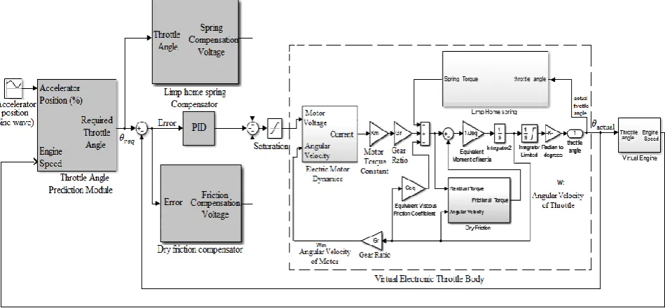
Proposed Electronic Throttle Control System
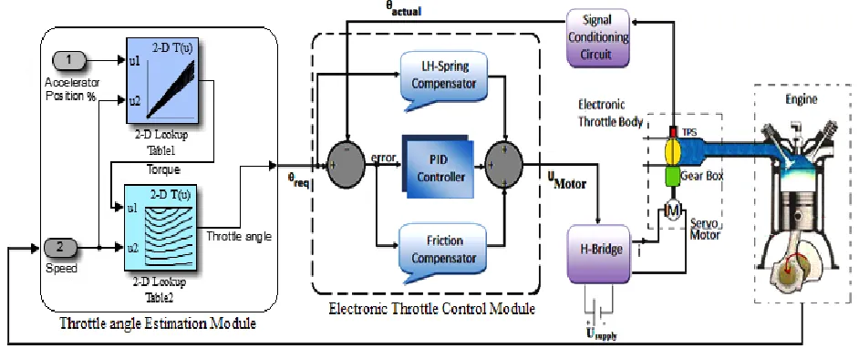
The proposed electronic throttle control system of a motorcycle engine consists of mainly two modules, one is throttle angle estimation module and other is the electronic throttle control module as shown in Fig. 4. In the proposed approach, torque demand by the driver is estimated for the given accelerator position and speed of the engine, further, the required throttle for the given torque demand is calculated and provided to the control system. The following section gives the description these two control modules in detail.
[image:6.595.85.556.521.712.2]3.1. Throttle Angle Estimation Module
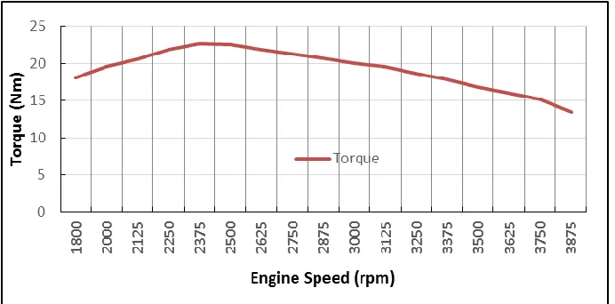
The throttle angle estimation module is the primary part of the electronic throttle control system. The proposed method for the throttle angle estimation follows an integrated approach of pedal follower and torque based strategies. In our proposed approach, the pedal follower method along with the consideration of driver torque demand is included for the throttle angle estimation strategy. The estimation module consist of two lookup tables, such as accelerator position map to interpret the driver torque requirement based on the accelerator position and the other one is throttle angle estimation map which is used to calculate the necessary throttle opening angle for achieving the torque demand. These two maps are simulated from the actual torque curve of the engine taken at the full throttle condition as shown in Fig. 5.
Fig. 5. Engine torque curve.
3.1.1. Accelerator position map
For the given accelerator position and speed of the engine, the torque demand by the driver is estimated as in Eq. (12):
Torque required = * Max torque at corresponding rpm (12)
[image:7.595.126.472.215.386.2]Fig. 6. Accelerator position map.
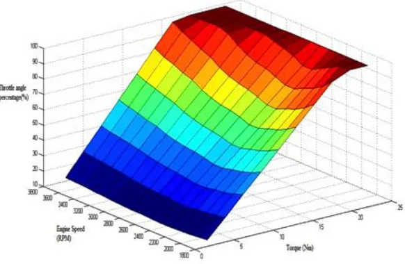
3.1.2. Throttle angle estimation map
For the required torque demand from the accelerator position map, the necessary throttle opening angle is obtained as in Eq. (13):
( (13)
Throttle angle estimation map shown in Fig. 7, is developed using the above equation for the driver torque demand from the previous map. Hence, the throttle angle is calculated based on the driver torque demand and corresponding engine speed. The estimated throttle angle ( is used as the input to the electronic throttle control system for accomplishing the driver demand by varying the position of the throttle valve.
Fig. 7. Throttle angle estimation map.
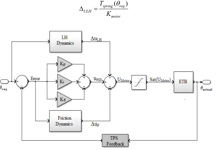
[image:8.595.183.449.85.278.2] [image:8.595.170.461.491.681.2]3.2. Control System Structure of Electronic Throttle Body
Based on the throttle angle requirement from the estimation module, the throttle control module has to adjust the position the throttle valve by considering the actual position (Ɵactual) of the valve by means of the
throttle position sensor (TPS). There is a position error of throttle valve (Ɵreq-Ɵactual) due to the nonlinear
behavior of the spring and friction characteristics in the throttle body, hence PID based closed loop control system along with compensators is followed for maintaining the throttle angle using the TPS signal act as a feedback shown in Fig. 8.
3.2.1. LH spring compensator
In the limp home dynamic region of the throttle valve, the initial torque is non-zero and there will not be any spring force acting because of the dual return spring. When the throttle is moved from mean position, there is a variation in the spring torque which creates the nonlinearity in the system. To eliminate the non-linearity created by the dual return springs at the limp home position, a feedforward compensator was developed based on the spring model as discussed in Section 2.3. Gain compensation is provided based on various reference throttle angle at the given limp home position. The spring torque compensation is calculated based on the different reference throttle angle using the different cases mentioned in Eq. (4). Hence the compensated voltage (∆ULH) is given in Eq. (14), and Km gives a relation between motor stall
voltage and corresponding stall torque. The resulted spring compensation voltage is feedforward into the throttle body system.
( )
spring req ULH
motor
T K
(14)
Fig. 8. Electronic throttle body control system module with compensators.
3.2.2. Friction compensator
Throttle plate creates a frictional torque (Tstatic) which opposes the direction of motion of butterfly valve
while opening or closing. Unlike viscous friction which is a linear function, dry friction has to be compensated because of its non-linear relationship due to the change in the direction of the throttle. Based on the angular velocity in the model, the friction value and sign are determined in the system. Hence, the parameters such as the throttle angle error, direction of throttle valve, and angular velocity are used for the estimating the friction compensation voltage (∆UF) which is given in Eq. (15). The corresponding voltage is
[image:9.595.125.478.367.613.2]( )
sstatic error UF
motor
T K
(15)
3.2.3. PID controller
PID controller provides the required correction (UPID) by comparing the required throttle angle with the
actual value obtained from the throttle position sensor and it continues till the required throttle angle is achieved by minimizing the error between the required and actual throttle angle values. The tuning of the PID is accomplished through the Ziegler-Nichols method, in order to give the better stability in the control system which is given as in Eq. (16),
0
( ) ( ) ( )
t
PID p req actual I req actual D req actual
d
U K K dt K
dt
(16)The final control system output voltage (UMotor) to the motor in the electronic throttle system is the
summation of the compensating voltages from limp home and friction compensators along with output from the PID controller (UPID) as in Eq. (17),
Motor PID ULH UF
U U U (17)
4.
Simulation Results and Discussion
A SIMULINK model for the proposed control system is developed as shown in Fig. 9 and a simulation study has been carried out to study the response of the throttle body for the step, sine wave and ramp input signals using hardware in loop (HIL) simulations and the results are presented in the following sections.
[image:10.595.79.554.437.657.2]Fig. 10. Schematic of Hardware in Loop (HIL) simulation of electronic throttle control.
The schematic experimental arrangement for HIL simulation consists of a data acquisition system, electronic throttle body with motor, position sensor, H-bridge driver circuit which provides the motor control signal to the motor as shown in Fig. 10. The actual throttle angle feedback is provided to the control system, by means of the position sensor through the data acquisition system.
4.1. Parameter Estimation of Electronic Throttle Body
The various parameters in the mathematical model of the electronic throttle body such as motor constant, spring constant, preload torque, etc. have to be estimated for the simulation and optimization of the electronic throttle body control system. In order to establish the various parameters of the throttle body, parameter estimation toolbox in MATLAB is used in this work. For the initial software in loop simulation of virtual throttle body, the values from the work done by [32, 34] are used. Model parameters of the throttle body are obtained by means of the multiple iterations and the final obtained values using estimation toolbox are tabulated in the Table 1.
In order to validate the obtained data, the Bosch electronic throttle body is tested for the different operating voltages to evaluate some of the parameters experimentally by means of motor stall test. Thus, the obtained values of the motor are such as the resistance (R) is 1.572 Ω, inductance (L) is 1.523mH and Kback emf is 0.0041Vs/rad. Hence the experimental values of the above mentioned parameters are closely
matched with the estimated parameters.
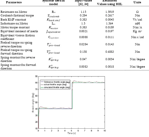
The response of the throttle body from the estimated parameters for the step input throttle angle signal is shown in Fig. 11. It can be seen that simulated and experimental curves are closely matching with the step input signal. Hence the estimated parameters can be used for the proposed control system design of the electronic throttle body.
4.2. Response of the Estimated Throttle Angle for the Sinusoidal Accelerator Position
For testing the performance of the control system, the simulation is carried out in SIL and HIL mode for the sinusoidal accelerator position. The throttle angle estimation module calculates the required throttle valve angle for given the accelerator position input as a sine function and the estimated values of throttle angle ( , is shown in Fig. 12.
the accelerator position, it is due to the variations of the torque demand at each position as the calculations for estimated throttle angle is based on the torque demand at different engine speed for the various accelerator positions.
Table 1. Estimated parameters of the electronic throttle body.
Parameters Symbols used in model Input values [32, 34] Values using HIL Estimated Units
Resistance on Motor Rm 1.15 1.5919 Ω
Coulomb frictional torque 0.284 0.2617 Nm
Back EMF constant 0.383 0.0045 Vs/rad
Inductance on Motor Lm 1.5 1.564 mH
Motor torque constant 0.383 0.0189 Nm/A
Equivalent moment of inertia 0.0021 0.0197 Kg. m2 Equivalent viscous friction
coefficient Cequivalent 0.0088 0.0111 Nm.s/rad
Preload torque on spring
reverse direction 0.0284 0.0143 Nm
Preload torque on spring
forward direction 0.158 0.6883 Nm
Spring constant for reverse
direction 0.047 0.0054 Nm/degree
Spring constant for forward
[image:12.595.66.563.162.644.2]direction 0.0083 0.0018 Nm/degree
[image:12.595.66.566.171.631.2]Fig. 12. Estimated throttle angle (Ɵreq) from throttle estimation module for accelerator position sine input.
4.3. Performance of the Proposed Control System with Compensator
The performance of the proposed control system against the nonlinearities such as friction and limp home spring position is examined for the sinusoidal accelerator position signal. The response of throttle body with the compensators for limp home and friction in the control system is represented in Fig. 13 (a).
It can be seen that actual throttle angle follows the required throttle angle signal closely with a very marginal error in both cases of simulated and actual conditions, however, there is a step cut in the output response of the throttle body at peak point of the input signal, as the maximum angle of 84.110 to avoid the
abnormal behavior of the engine and the minimum angle is found to be 8.30 to avoid the stalling of engine.
These results demonstrate the robustness of the proposed control system against nonlinearities such as friction and limp home spring position.
[image:13.595.79.525.505.732.2]Figure 13(b) shows the throttle angle error (Ɵreq-Ɵactual) between actual and simulated conditions, it
indicates that there is very small variation in the order of 0.5 degree variations in the regions other than peak and dip of the required throttle angle response, but the error during the peak of the required throttle angle is in the range of 1.5 degrees and during the dip is in the range of 2.2 degrees. These errors may be due to the aging effects of throttle and position sensor, variations of external temperature and battery voltage, production deviation etc., which are not considered in the control system design.
Fig. 13(b).Comparison of throttle angle error with compensator for sine input.
[image:14.595.70.552.186.406.2] [image:14.595.76.528.448.675.2]4.4. Performance of the Proposed Control System without Compensator
The response of throttle body without compensators in the control system, for the sinusoidal accelerator position input is shown in Fig. 14(a). It indicates that there is a larger deviation between the actual and simulated throttle angle as compared to the actual throttle angle provided by the control system with compensator as shown in Fig. 13(a). It can be seen from Fig. 14(b) that the throttle angle variation is in the range of 2 degrees at the peak and 3 degrees during dip of the curve.This error is due to the nonlinear effects of limp-home and friction which causes the response of throttle angle variation and affects the performance of the control system. Hence the curve clearly indicates that the there is a need of improving the response of the control system in those regions by extending the PID controller along with the limp home and friction compensators. This result proves the necessity of the compensators in the control strategy in order to tackle the nonlinearities of the system
Fig. 14(b). Comparison of throttle angle error without compensator for sine input.
4.5. Response of Throttle Body for the Ramp Input Signal with Compensator
Figure 15 shows the response of the throttle angle for the accelerator position input as ramp signal. It can be seen that the response of the throttle body shows a deviation at the beginning as compared with the input ramp signal so as to maintain the minimum position of throttle angle of 8.340deg and reaches up to
the maximum position at the peak position of 840deg. From these results, it is concluded that the proposed
[image:15.595.77.538.245.456.2]Fig. 15. Simulated and actual throttle angle for accelerator position input with compensators for ramp input.
5.
Conclusion
The work presented in this paper discuss the combination of pedal follower and torque based approach for the precise estimation of throttle angle required for the given torque demand. In the proposed method, the mass airflow is not considered for the throttle angle calculation which causes the lesser computational time and storage memory in the controller. As the torque demand is also included in the throttle angle estimation, proposed electronic control system can be easily integrated with the other systems such as catalyst heating, traction control, etc. In the proposed control system, the complexity in controlling the electronic throttle system due to non-nonlinearities such as friction and limp home spring is also addressed in this work using the mathematical and compensators. Performance of the proposed control system with compensators was tested using step, sinusoidal and ramp input signals and the results prove that the designed control system has the ability to follow the calculated throttle angle for both simulated and actual conditions. Also the throttle angle error value was found to be very marginal with compensators to handle the nonlinearities in the system.
References
[1] J. Wengert, D. Rommel, and R. Krzok, “Electronic throttle control for motorcycles,” SAE Technical Paper No. 2007-32-0044, 2007.
[2] R. Conatser, J. Wagner, S. Ganta, and I. Walker, “Diagnosis of automotive electronic throttle control systems,” Control Engineering Practice, vol. 12, no. 1, pp. 23-30, 2004.
[3] M. Tanelli, C. Vecchio, M. Corno, A. Ferrara, and S. M. Savaresi, “Traction control for ride-by-wire sport motorcycles: A second-order sliding mode approach,” IEEE Transactions on Industrial Electronics, vol. 56, no. 9, pp. 3347-3356, 2009.
[4] J. B. Song and K. S. Byun, “Throttle actuator control system for vehicle traction control,” Mechatronics, vol. 9, no. 5, pp. 477-495, 1999.
[5] M. Corno and S. M. Savaresi, “Experimental identification of engine-to-slip dynamics for traction control applications in a sport motorbike,” European Journal of Control, vol. 16, no. 1, pp. 88-108, 2010. [6] R. Grepl and B. Lee, “Modeling, parameter estimation and nonlinear control of automotive electronic
throttle using a rapid-control prototyping technique,” International Journal of Automotive Technology, vol. 11, no. 4, pp. 601-610, 2010.
[image:16.595.74.527.84.305.2][8] K. Hazu and M. Yokoyama, “Model based control system design and control strategies on ETC,” SAE Technical Paper No. 2008-32-0038, 2008.
[9] B. Smither, J. Allen, P. Ravenhill, G. Farmer, P. Grosch, and E. Demesse, “Development of electronic throttle actuation for a 50cc 2-stroke scooter application,” SAE Technical Paper No. 2011-32-0581, 2011.
[10] S. Satou, S. Nakagawa, H. Kakuya, T. Minowa, M. Nemoto, and H. Konno, “An accurate torque-based engine control by learning correlation between torque and throttle position,” SAE Technical Paper No. 2008-01-1015, 2008.
[11] G. Panzani, M. Corno, and S. M. Savaresi, “On adaptive electronic throttle control for sport motorcycles,” Control Engineering Practice, vol. 21, no. 1, pp. 42-53, 2013.
[12] G. Panzani, M. Corno, and S. M. Savaresi, “Design of an adaptive throttle-by-wire control system for a sport motorbike,” in 18th IFAC World Congress, 2011, vol. 18, no. 1, pp. 4785-4790.
[13] M. Corno, M. Tanelli, S. M. Savaresi, and L. Fabbri, “Design and validation of a gain-scheduled controller for the electronic throttle body in ride-by-wire racing motorcycles,” IEEE Transactions on Control Systems Technology, vol. 19, no. 1, pp. 18-30, 2011.
[14] M. Corno, M. Tanelli, S. M. Savaresi, and L. Fabbri, “Electronic throttle control for ride-by-wire in sport motorcycles,” in Proc. IEEE International Conference on Control Applications, 2008, pp. 233-238. [15] A. Beghi, L. Nardo, and M. Stevanato, “Observer-based discrete-time sliding mode throttle control
for drive-by-wire operation of a racing motorcycle engine,” IEEE Transactions on Control Systems Technology, vol. 14, no. 4, pp. 767-775, 2006.
[16] A. Beghi, L. Nardo, and M. Stevanato, “A sliding mode throttle controller for drive-by-wire operation of a racing motorcycle engine,” in Intelligent Control, 2005. Proceedings of the 2005 IEEE International Symposium on Control and Automation, pp. 557-562.
[17] C. Yang, “Model-based analysis and tuning of electronic throttle controllers,” SAE Technical Paper No. 2004-01-0524, 2004.
[18] A. Thomasson and L. Eriksson, “Model-based throttle control using static compensators and IMC based PID-design,” in IFAC Workshop on Engine and Powertrain Control, Simulation and Modeling, 2009. [19] J. Deur, D. Pavkovi, N. Peri, M. Jansz, and D. Hrovat., “An adaptive nonlinear strategy of electronic
throttle control,” SAE Technical Paper No. 2004-01-0897, 2004.
[20] D. Pavkovic, J. Deur, M. Jansz, and N. Peric, “Adaptive control of automotive electronic throttle,”
Control Engineering Practice, vol. 14, no. 2, pp. 121-136, 2006.
[21] M. Baric, I. Petrovic, and N. Peric, “Neural network-based sliding mode control of electronic throttle,” Engineering Applications of Artificial Intelligence, vol. 18, no. 8, pp. 951-961, 2005.
[22] X. Yuan and Y. Wang, “Neural networks based self-learning PID control of electronic throttle,”
Nonlinear Dynamics, vol. 55, no. 4, pp. 385-393, 2009.
[23] G. Lifeng and C. Ran, “A fuzzy immune PID controller for electronic throttle,” IEEE Second International Symposium on Computational Intelligence and Design, vol. 1, pp. 72-75, 2009.
[24] G. Banish, Engine Management: Advanced Tuning. CarTech Inc., 2007.
[25] J. Hartman, “How to tune and modify engine management systems,” in Motorbooks International, 2004. [26] G. L.Solliec, F. L.Berr, G. Corde, and G. Colin, “Downsized SI engine control: A torque-based design
from simulation to vehicle,” SAE Technical Paper No. 2007-01-1506, 2007.
[27] N. Heintz, M. Mews, G. Stier, A. J. Beaumont, and A. D. Noble, “An approach to torque-based engine management systems,” SAE Technical Paper No. 2001-01-0269, 2001.
[28] P. Bumroongsri and S. Kheawhom, “MPC for LPV systems based on parameter-dependent Lyapunov function with perturbation on control input strategy,” Engineering Journal, vol. 12, no. 2, pp. 61-72, 2012.
[29] H. Jimbo and H. Nakayama, “Development of DBW system for motorcycles with fast response and layout flexibility,” SAE Technical Paper No. 2012-32-0051, 2012.
[30] U. Montanaro, A. Gaeta, and V. Giglio., “Robust discrete-time MRAC with minimal controller synthesis of an electronic throttle body,” IEEE/ASME Transactions on Mechatronics, vol. 19, no. 2, pp. 524-537, 2014.
[31] T. Abe, Y. Asada, M. Tsuyuguchi, R. Yamazaki, and K. Hotta, “Research of electronically controlled throttle system for large motorcycles,” SAE Technical Paper No. 2009-01-1047, 2009.
[33] T. Sakamoto, T. Oshima, T. Yoshiaki, M. Fukuuchi, and S. Kuratani, “Development of fail-safe method for motorcycle’s electronic throttle control system,” SAE Technical Paper No. 2009-32-0124, 2009.