Effects of Nanofluid Flow in Micro channel Heat
Sink for Forced Convection Cooling of Electronics
Device: A Numerical Simulation
Arvind Kumar Patel, Sushant Bhuvad, S.P.S. Rajput
Abstract: A computational study is carried out on a rectangular microchannels heat sink using nanofluids flow for cooling of electronics device under uniform heat flux condition. In the present investigation water, ethylene glycol and a mixture of ethylene glycol (20%wt) and water are considered as base fluids with varying concentration of five different nanoparticles includingAl2O3, TiO2, CuO, SiO2 and ZnO. Numerical computations are performed using ANSYS Fluent software by considering the single phase model and results are validated with available experimental and numerical data. Further parameters like thermal resistance, pumping power, local heat transfer coefficient and temperature variation of IC chip are presented and analysed. It was noted that with addition of nanoparticles there is sharp increment in local heat transfer coefficient and decrements in local thermal resistance compared to base fluid but at same time viscosity of fluid increases that provide more drag or pressure drop which ultimately increases the pumping power.
𝑪𝒖𝑶-Water nanofluid of concentration 1% and 4% give large improvement in heat transfer parameters and at the same time there is little enhancement in pressure losses or pumping power also it has less cost and more stability in base fluid as compared to other nanofluids.
Keywords: Electronics cooling; Nanofluid flow; Microchannel; ANSYS Fluent; Local heat transfer coefficient; Pumping power
I. INTRODUCTION
Despite the development in the field of electronics device to manufacture high performance IC (Integrated Circuit) chip, the remove of heat from IC chips is main concerned. Since now days IC chips are more compact leading to produce higher heat flux in smaller area which increase its working temperature that causes decreasing device efficiency or life span if it is not properly cooled. Even water or some dielectric fluid flow cooling, using mini-channels or micro-channels heat sink cannot meet requirement of some of high heat flux IC chips. Hence there is increased in interest of nanofluids flow through microchannels heat sink since the study shows that there is large enhancement in thermophysical properties of base liquid even for a smaller addition of nanoparticles. Nanofluids considered as mixture of two-phase flow, composed of base liquid and extremely fine particles having dimension below 100 nm. Azizi et al. [1] examined the heat dissipation performance of cylindrical shape microchannels in a liquid heat sink to cool electronics devices using CuO– Water nanofluid.
Revised Manuscript Received on December 05, 2019.
Arvind Kumar Patel, Department of Mechanical Engineering, Maulana Azad National Institute of Technology, Bhopal 462003, INDIA
Sushant Bhuvad, Department of Mechanical Engineering, Maulana Azad National Institute of Technology, Bhopal 462003, INDIA
S.P.S. Rajput, Department of Mechanical Engineering, Maulana Azad National Institute of Technology, Bhopal 462003, INDIA
The concrete observations made that, for concentrations of 0.05, 0.1 and 0.3 mass percentages of CuO–Water nanofluid the Nusselt numbers increases by 17%, 19% and 23% respectively in contrast with water.
Ramon Ramirez et al. [2] demonstrates numerical study to improve heat transfer parameters for laminar nanofluids flow in case of straight microtube, for constant wall temperature and uniform heat flux conditions. It was studied that there is enhancement in Nusselt number up to 16% for 4% concentrations of Al2O3 in water as compared to water
and 8% for Al2O3-Turbine oil as compared to turbine oil.
Dongsheng et al. [3]performed experiment using Al2O3nanoparticles with water as a base fluid in case of
laminar fluid flow in circular tube and studied that local heat transfer coefficient increases up to 47% for 1.6% concentration. Kim et al. [4] demonstrates the nanofluids flow in tube under laminar and turbulent condition. They found that increment in heat transfer coefficient near inlet is due to Brownian motion take place in nanofluids. Piyanut et al. [5] examined TiO2-Water nanofluid in microchannel heat
Effects of Nanofluid Flow in Micro channel Heat Sink for Forced Convection Cooling of Electronics
Device: A Numerical Simulation
Nomenclature
Lelea et al. [
Error! Reference source not found.
] performs simulation studies of Al2O3-Water nanofluids instraight microtube for efficient cooling purpose in various applications. Single-phase approach method is used to perform the simulations. In this analysis Reynolds numbers taken as a constant; from results studied that the heat transfer characteristics enhanced in case of nanofluids compared to water but for constant pumping power the results achieved from nanofluids were very close to water case coolant. That indicates; here nanoparticles did not effectively reduce surface temperature as compared to water base fluids. W. Escher et al. [7] used silica nanoparticles suspensions in aqueous medium for electronics device cooling through microchannels sinks. Authors studied nanofluids for three different sizes of nanoparticles and find out the thermal- characteristics by varying the flow rate through microchannels. They observed that size of nanoparticles affects the thermal-characterises of system. From all the above literature survey, it is evident that sufficient research has been carried with regard to mini or microchannels heat sink using different concentration of nanoparticles in base fluid and also for different geometry models for various applications. However, little has been reported with respect to specific study in case of IC chips for various combinations of nanoparticles and also by varying their concentration in different base fluids like in case of Ethylene glycol and water mixture type base fluid. Further optimises the dimensions of geometry, velocity, nanoparticles concentration and also study nanofluids effects on pressure drop which affect the pumping power. Therefore, in the present work this particular aspect will be investigated thoroughly with a view that an optimum geometric configuration and nanoparticles concentration in particular base fluid ought to have greater heat transfer coefficient and consequently leading to better cooling
efficiency also less pumping power requirement. In this paper, five different oxide nanoparticles; by varying their concentration in three types of base fluids using optimise dimensions of rectangular microchannels heat sink will be analysed numerically using commercially available CFD software ANSYS Fluent.
The remaining part of this research article is divided into four sections and each section subdivided further. In the next section physical model and computational domain for numerical analysis is studied also thermos-physical properties of nanofluid and basic formula used in this article is discussed. This is followed by a mathematical formulation section which is subdivided in 3 parts. Here governing equation, boundary conditions, numerical approach for simulation and grid independency test is presented. In the results; validation of geometry and other parameters is performed by comparing the outcomes of simulation with previous work and then effects of nanoparticles in base fluid on different heat transfer characteristics and pumping power is analysed. In final section some remarks are concluded from this article.
II. PHYSICAL MODEL
2.1 Micro channel configuration:
Fig.1 is the illustration of heat sink with heat supplied through a 1cm x 1cm (𝐿ℎx𝑊ℎ) Integrated Circuit (IC) Chip
from bottom and it is removed by flowing fluid through microchannels. Chip is located near the inlet of the microchannels and centred across the width of heat sink as shown in Fig.1. A uniform heat flux q is provided through IC chip. The
inlet temperature of fluid is 293K. There are three different cases of microchannels dimensions are considered in this study and their dimensions are discussed in Table1. Case 3 dimensions are optimise by numerical
Fig.1. (a) Simplified diagram of microchannels; (b) Dimensions of the IC chip and sink.
Table1. Dimension for three different sets of micro channels
In
Numerical method it is difficult and time consuming to study whole heat sink body because of that a simplified single microchannel domain is consider as shown in Fig.2. But care must be taken while modelling this single domain as if an outer edge of microchannel heat sink is consider then here actual heat flux input may be zero or smaller than IC chip heat input. Therefore microchannel at the centre of heat sink is considered for our study. Here heat flux is almost same as an IC chip heat input because there is very little heat spreading towards outer side of sink. In case of experiment the top wall of heat sink is made of glass which is exposed to a surrounding ambient air. The conductivity of glass wall is quite lower compare to heat sink material so there are negligible heat transfer through this wall hence here top wall is considered as adiabatic. The remaining boundary conditions for this single domain are discussed in next sections. After selecting a domain Finite Volume Method (FVM) is used for analysis. There are number of scheme available to solve FVM problem; here second order up wind scheme is used as it is more stable. But at same time its accuracy is less than other scheme for same number of grid nodes hence more number of grid nodes is used here to improve accuracy.(a)
(b)
Effects of Nanofluid Flow in Micro channel Heat Sink for Forced Convection Cooling of Electronics
Device: A Numerical Simulation
2.2 Thermo physical Properties:
Here properties of base fluids, nanoparticles and heat sink material are considered as constant. The criteria for selection of the base fluid are; the stability for nanoparticles is high in
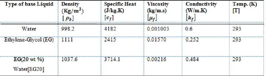
this base fluid, having low cost, higher boiling point and easy availability. There are three type of base fluid is considered here and their properties are given in
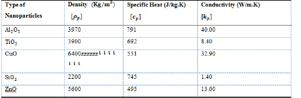
Table 2. In this study oxide nanoparticles of spherical size are considered as they have less cost, more stability in given base fluid as of other nanoparticles. Also they have good required thermal conductivity for effectively cooling of electronics device. The properties of five different nanoparticles are presented in Table 3. These properties are studied from research article [
Error! Reference source not found.
-Error! Reference
source not found.
]. Standard size of nanoparticles is considered in this study as size of nanoparticles affects the heattransfer parameters. In
Table 4 heat sink material properties are given. Here silicon is considered as heat sink material for validation purpose and for further study aluminium is selected as heat sink material as it has more thermal capacity and it also have more thermal conductivity than silicon so it can effectively remove heat from electronics device. For numerical analysis thermo-physical properties of nanofluid has to be known which can be found from the standard
available formula. In
[image:4.595.48.528.178.334.2] [image:4.595.86.299.428.788.2]Table 2. Thermophysical properties of base liquids.
[image:5.595.69.534.76.209.2]Table 3. Thermophysical properties of nanoparticles.
Effects of Nanofluid Flow in Micro channel Heat Sink for Forced Convection Cooling of Electronics
Device: A Numerical Simulation
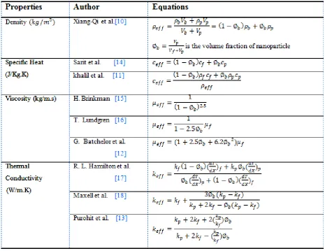
Table 5. Thermo physical properties equations of nanoparticle To find out different parameters of heat transfer
characteristics following equations is used, Local thermal resistance,
𝑅 =𝑇𝑚𝑎𝑥 𝑧 − 𝑇𝑖𝑛
𝑞 (1)
Here, R is local thermal resistance at z cm from the inlet 𝑇𝑚𝑎𝑥 𝑧 ,is maximum temperature of fluid at z cm from the
inlet
𝑇𝑖𝑛, is inlet temperature of fluid
q, is heat flux from IC chip Hydraulic diameter,
𝐷ℎ =
4𝐴 𝑃 =
2𝐻𝑐𝑊𝑐
𝐻𝑐+𝑊𝑐
(2)
Reynolds number, 𝑅𝑒 =𝜌𝑤𝑎𝑣𝑔𝐷ℎ
𝜇 (3) Local convection heat transfer coefficients, ℎ𝑧 =
𝑞 𝑇𝑤𝑎𝑙𝑙 − 𝑇𝑏
(4)
Where, 𝑇𝑤𝑎𝑙𝑙and 𝑇𝑏is average temperature of wall and bulk
mean temp of fluid at z cm plane respectively. Pump power,
𝑃𝑝𝑢𝑚𝑝 = ∆𝑝 𝑥 𝑄 𝑎 (5)
Where, ∆𝑝 = Pressure drop.
III. MATHEMATICAL FORMULATION
3.1
Governing equationsIn this paper Cartesian tensor system is used for solving the numerical problem. Some simplifying assumptions are made before applying continuity, momentum and energy equation, (1) No slip condition. (2) Fluid flow and heat transfer is in Steady state. (3) Fluid is incompressible. (4) Heat flux is uniform. (5) Constant solid and fluid thermo-physical properties (6) negligible radiation heat transfer. Boundary conditions
Hydrodynamic Boundary conditions,
For all boundary condition other than inlet and outlet, velocity is zero.
1. At inlet, u=0, v=0, w= 𝑉𝑖𝑛
For z=0, 𝑊𝑠
2<x< 𝑊𝑠
2+𝑊𝑐 and 𝐻𝑡− 𝐻𝑐 < 𝑦 < 𝐻𝑡
To calculate inlet velocity of fluid, assumption is made that fluid is evenly distributed in all microchannels
2. at outlet, 𝑃1= 𝑃𝑜𝑢𝑡
For z=𝐿𝑡, 𝑊𝑠
2<x< 𝑊𝑠
2+𝑊𝑐 and 𝐻𝑡− 𝐻𝑐 < 𝑦 < 𝐻𝑡
Thermal Boundary conditions,
Adiabatic conditions are assumed for all the boundaries of the solid region except at heat sink bottom wall; where uniform heat flux is applied.
𝜕2𝑇
𝜕𝑥2+
𝜕2𝑇
𝜕𝑦2+
𝜕2𝑇
𝜕𝑧2
= 0 (6) Which also follow the below boundary conditions,
1. −𝑘𝑠
𝜕𝑇 𝜕𝑦 =
𝑞 (7) For 0< z <𝐿ℎ,
𝑊𝑡−𝑊ℎ 2 < x<
𝑊𝑡+𝑊ℎ
2 and y=0
2. At inlet T=𝑇𝑖𝑛
For z=0,𝑊𝑠
2< x < 𝑊𝑠
2+𝑊𝑐 and 𝐻𝑡− 𝐻𝑐 < 𝑦 < 𝐻𝑡
3. Flow is considered to be fully developed at the channel outlet
∂2T
∂z2= 0 (8)
For z=𝐿𝑡, Ws
2< x < Ws
2 +Wc and Ht− Hc< 𝑦 < Ht
According to Langhaar equation,
The entrance length for fully developed laminar flow is =
0.057*Re*𝐷ℎ.
This is fulfilled here for all conditions. Continuity
𝜕𝑤
𝜕𝑧 = 0 𝑜𝑟 𝑤
= 𝑤(𝑥, 𝑦) (9) Momentum
Z-momentum 𝜕2𝑤
𝜕𝑥2+
𝜕2𝑤
𝜕𝑦2 =
1 𝜇 𝑑𝑃 𝑑𝑧 =1 𝜇 𝑑𝑃 𝐿𝑧 (10) Energy 𝑤𝜕𝑇 𝜕𝑧= 1 𝛼
𝜕2𝑇
𝜕𝑥2+
𝜕2𝑇
𝜕𝑦2+
𝜕2𝑇
𝜕𝑧2 11
Where, 𝛼 = 𝑘
𝜌𝑐
3.2 Numerical method:
This paper consists of numerical study of different nanofluids for improvement of heat transfer characteristics of base fluid and optimise fluid performance that is simulated on CFD software ANSYS FLUENT 13.0 using single phase approach method, broadly single phase approach (SPH) assumes that both nanoparticles and base fluid have same velocity filed and temperature. From this all assumption a 3-D microchannel heat sink model is developed. Standard Viscous-Laminar model is opted and a relaxation factor of 0.3 is taken as initial iteration value. In solver a steady time with absolute velocity formation is taken and solver is kept at simple pressure based. Momentum and species are of second order upwind spatial discretization. The Under-Relaxation factor for the pressure, momentum, energy and other species equation is 0.3, 0.7, 1.0 and 1.0 respectively. The residuals of the momentum and the other component
equations are set to
1 x 10
−4,
for
energy equation it is 1x 10⁻⁶ and for continuity equations 1x 10−3.3.3 Grid Independency:
(b)
[image:7.595.55.459.35.497.2](a)
Fig. 3. Optimum Grid system of model (a) Sectional view; (b) front partial view.
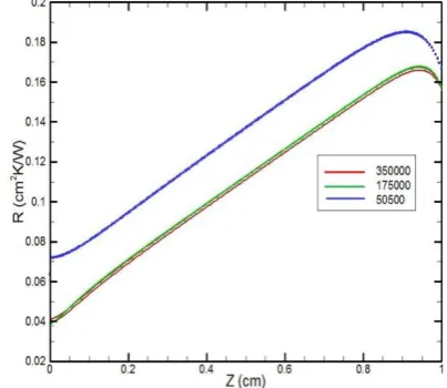
Fig. 3 demonstrates the partial grid of the microchannel modelled on the CFD software. To get reliable results mesh created is structured and uniform. To understand the influence of the grid size on results, grid independency test is performed by taking case 1 dimension; where similar results were compared at different values of grid sizes and the optimum grid size is selected that would not only give best results but reduce processing power required that leads to early convergence of results. Fig.4 compares variation of local thermal resistance along fluid flow axis at different grid sizes for water fluid. An error of 24.3 % was observed with 50500 numbers of elements despite early convergence of results, where as there is only 0.5% deviation in results between 175000 and 350000 elements. But higher number of elements increases the computation time which restricts number of trails possible in the time period and it also allotted more CPU memory, hence optimum grid size with 175000 elements is opted.
[image:7.595.307.532.54.307.2] [image:7.595.325.527.540.715.2]Effects of Nanofluid Flow in Micro channel Heat Sink for Forced Convection Cooling of Electronics
Device: A Numerical Simulation
IV. RESULTS AND DISCUSSIONS
4.1
Model validationTo verify the models the results obtained from simulation are validated with previous experiment and numerical work available from literature survey [
Error!
Reference source not found.
-Error! Reference source
not found.
]. (b)
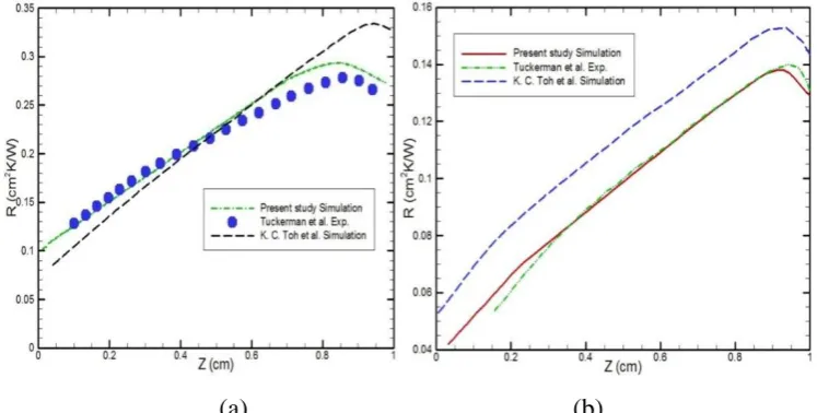
Fig. 5 (a) and (b) shows variation of thermal resistance for case 0 and case1geometries with water as a working fluid and silicon as a heat sink material for the simulation and experimental results respectively. The local thermal resistance calculated from present study from equation 1 is compared with K. C. Toh et al. [19] simulation and Tuckerman’s [20] experimental work as shown in
Table 6. The simulation results are in good agreement with experimental data. There is little deviation seen in present study graph and Tuckerman’s experimental work because of the assumptions made in present study such as adiabatic wall consider in this study but in experimental case there is glass wall at outer side of heat sink also there is some uncertainty in experimental reading measurement. There is
little deviation in present study and K. C. Toh simulation work because of difference between numbers of elements. From this simulations studied that thermal resistance is goes on increasing along a Z direction and it is maximum near Z=0.9 cm hence for further study this plane is selected for our analysis.
(a)
(b)
Fig. 5. Comparison of local thermal resistance with experimental and numerical study along fluid flow: (a) for case-0; (b)
case-1.
Table 6. Comparison of local thermal resistance [R] with previous work along fluid flow.
R (cm2K/W) For case 0 along z direction (cm) For case 1 along z direction (cm)
0.1 0.3 0.5 0.7 0.9 0.1 0.3 0.5 0.7 0.9
Present Study 0.1258 0.1761 0.2264 0.2768 0.2881 0.0513 0.0778 0.0987 0.1196 0.1375
Tuckerman’s experimental work
--- 0.1810 0.2197 0.2576 0.2756 ---- 0.0762 0.0999 0.1200 0.1379
K. C. Toh et al. simulation
0.1046 0.1662 0.2225 0.2790 0.3298 0.0688 0.0950 0.1156 0.1347 0.1524
[image:8.595.111.485.246.435.2](a)
[image:9.595.65.274.50.228.2](b)
Fig.6. Change in Reynolds Number: (a) variation of local thermal resistance at z =0.9 cm plane; (b) variation of
pumping power.
After performing validation of model successfully with previous experiment and numerical work now further study can be presented; here number of simulations is studied with combination of three different base fluid and five different nanoparticles by varying their concentration from 0-10% with respect to volume fraction and effects of various nanofluid on thermal resistance, convective heat transfer coefficient and power required by pump is analysed. 4.2 Effects of nanofluids by varying nanoparticles concentration in deionised Water.
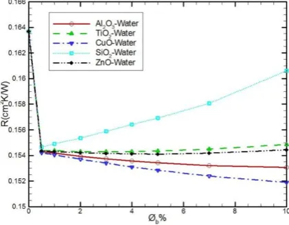
Aluminium is the material used for heat sink construction, IC chip is made of silicon material and case three dimensions are used here for numerical analysis. Fig.7a demonstrates local thermal resistance variation with change in percentage concentration of five oxide nanoparticles. Typically, it is evident that for volume fraction of 0.005 thermal resistances is decrease up to 5.62 percentages for all different nanoparticles except for SiO2 it
is decrease by 5.38 percentages. Thermal resistance decreases sharply with small concentration of nanoparticles mixture because even addition of a 0.5% concentration of Al2O3 in water increase thermal conductivity of base fluid
by 70.17 percentage. Al2O3 and CuO have large
conductivity so addition of higher concentration of them decreases thermal resistance further. In case of CuO decrement is more since its heat capacity (𝜌𝑐𝑝) is higher
than Al2O3. In case of other nanoparticles thermal resistance
remain constant or increases slowly as their concentration increase, as they have smaller thermal conductivity and heat capacity also at the same time their viscosity increases.
(a)
(b)
Fig.7. Effects of change in concentration of nanoparticles using base fluid as water: (a) On local thermal resistance at z =0.9cm plane; (b) on pumping power requirement.
[∅𝐛%=Percentage concentration of nanoparticles]
Fig.7b indicates that nanoparticles increases pumping power because of increasing wall shear stress or viscosity that produces more pressure drop. For smaller percentage of nanoparticles there is negligible change in pumping power but as concentration increases drag force or viscosity increases which increase pumping power. Above 4 percentage of nanoparticles concentration pumping power increases sharply. The pumping power is same for different nanoparticles because it only depends on viscosity of base fluid and concentration of nanoparticles in case of single phase approach method. Here Brownian motion effects cannot be analysed. The same effects is also analysed in G. Batchelor et al. [13] literature article.
Fig. 8 is a plot of change in local convection heat transfer coefficient at Z=0.9 cm plane for varying concentrations of nanoparticles which show that there is 47.35% of increment in heat transfer coefficient for 0.5% concentration of Al2O3
in water and for 4% of Al2O3 it is 61.53% when compared
with water. That indicates large improvement in heat transfer characteristics using nanofluids in microchannels. For smaller concentration improvement is almost equal for all nanoparticles but as a concentration increases there is divergence; for Al2O3and CuO it is more almost equal.
There is linear improvement in heat transfer coefficient as concentrations of nanoparticles are increases.
Fig. 8. Change in local heat transfer coefficient at z =0.9cm plane for different concentration of
[image:9.595.321.532.51.232.2] [image:9.595.64.275.616.780.2]Effects of Nanofluid Flow in Micro channel Heat Sink for Forced Convection Cooling of Electronics
Device: A Numerical Simulation
A concrete observation is made from above figures and through other studies that CuO nanofluid has to be first choice as it gave less thermal resistance, low pumping power, low cost and more stability in water compare to other nanoparticles in case of water base fluid and also there is large enhancement in local heat transfer coefficients or average heat transfer coefficient and second choice is Al2O3
nanoparticles which also give almost same improvement in heat transfer parameters compare to CuO but it have more cost, less stability in water and provide more thermal resistance for same concentration.
(a)
(b)
[image:10.595.327.526.51.247.2](d)
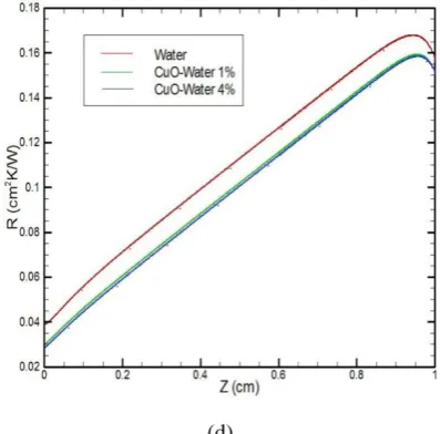
Fig. 9. Comparison with water for (a) and (c) variation in IC chip temperature; (b) and (d) change in local
thermal resistance along a flow: for 1% and 4% concentrations of 𝐀𝐥𝟐𝐎𝟑 and CuO in water case.
Further effects of CuO and Al2O3 nanoparticles on IC
chip temperature and thermal resistance along a fluid flow is studied. Comparison is made in between water, 1% and 4% of nanoparticles concentration as shown in above figures. Only this specific concentration of nanoparticles is studied in case of water base nanofluid since above 4% concentration pressure drop is more, stability is decreases and fluid cost also goes on increases but at same time there are negligible changes in heat transfer parameters.
From Fig. 9 seen that IC chip temperature and thermal resistance increases linearly throughout fluid flow direction except near inlet for vary short distance of region; which indicated that flow is thermally developing near inlet and after that short distance it is fully developed. Thermal resistance increases along fluid flow till 0.9 cm because along a flow its temperature goes on increasing as there is convection phenomena take place between fluid and heat sink which increases molecular momentum of fluid which oppose heat transfer phenomena and at same time IC chip provide uniform heat flux up to 1cm. After z=0.9 cm thermal resistance once again start decreasing as heat from IC chip near z = 1cm is spread not only along y direction but also along z direction in to the heat sink through conduction which decreases the IC chip temperature and thermal resistance. There is up to 1℃ decreasing in temperature of IC chip in case of Al2O3-Water and CuO-Water nanofluids
Fig. 10 represent the temperature variation in ANSYS Fluent at Z =0.9 cm plane for Al2O3and CuO nanoparticles
from 0 to 10 percentages concentrations. It seen that as concentration of nanoparticles increases the minimum
[image:11.595.81.516.47.355.2]temperature of fluid is increases because of increasing conductivity of fluids and at same time the heat sink maximum temperature is decreases that indicated increasing heat transfer coefficients which reduces chip temperature.
Fig.10. Temperature variation for different concentration of 𝐀𝐥𝟐𝐎𝟑-Water and CuO-Water nanofluids at Z= 0.9 cm
plane. 4.3 Effects of nanofluids by varying nanoparticles concentration in pure Ethylene Glycol (EG).
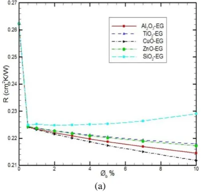
FromFig.11a studied that in case of ethylene glycol; same nature of graph is follow for respective nanoparticles when compared with water base fluid. There is sharp decrement in thermal resistance; in case of 0.5% nanoparticles concentration thermal resistance is decrease by 14.6 % and after that it is decreases effectively mostly in case of Al2O3 and CuO nanoparticles as their concentration
increases. Here thermal resistance is higher than water as ethylene glycol has low conductivity. Viscosity of ethylene glycol is very high compare with water so pumping power required is more; that is up to 450 watt for pure Ethylene Glycol. In Fig.11b pumping power variation with respect to concentration of nanoparticles is shown. Here only CuO-EG and Al2O3-EG graph is shown because as discuss in case of
water pumping power does not depend on type of nanoparticle. For the pumping power also graph follows same nature of trend as in case of water base fluid. For addition of 0.5 percentages of nanoparticles pumping power requirement increases up to 455 watt. From this study conclusion can be made that water is best choice to use as base fluid instead of ethylene glycol as it have low cost, make more effective cooling of electronics devices and required less power to operate. Ethylene glycol is preferable
for higher working temperature condition as it has higher boiling temperature than water which is not case here.
[image:11.595.326.528.527.721.2]Effects of Nanofluid Flow in Micro channel Heat Sink for Forced Convection Cooling of Electronics
Device: A Numerical Simulation
[image:12.595.68.277.51.244.2](b)
Fig.11. Effects of different concentration of nanoparticles using base fluid as Ethylene glycol: (a) on
local thermal resistance at Z= 0.9 cm plane; (b) on pumping power requirement.
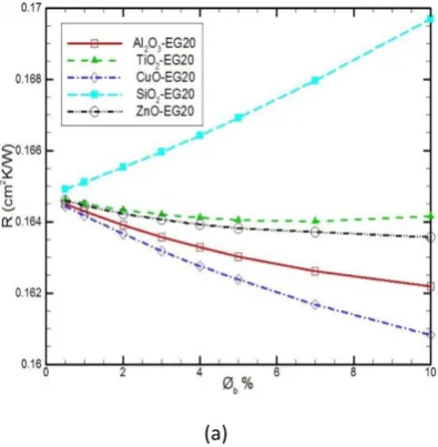
[image:12.595.320.529.53.252.2]4.4 Effects of nanofluids by varying nanoparticles concentration in EG-Water mixture Where 20 wt% of ethylene glycol is used in water [EG 20].
Fig.12a demonstrates thermal resistance variation with change in percentage concentration of five nanoparticles for EG20 base fluids. It analyzed that thermal resistance is decreases up to 36.52% in case of 4% concentration of CuO in base fluid and for same concentration of Al2O3 it is
36.13% when compare with pure ethylene glycol fluid. Here decrement in thermal resistance is very sharp as ethylene glycol have low conductivity and when water and nanoparticles is added in it, its conductivity increase up to 3 times. The viscosity of EG-20 is quite higher than water but lower than pure Ethylene glycol. Hence pumping power requirement of EG20 is in between the water and EG type base fluid. From Fig. 12b studied that in case of EG20 pumping power requirement is 63 watt and when 0.5 % of nanoparticles is added in it is increases up to 64 watt. For lower concentration of nanoparticles the increment is less but above 4% concentration pumping power requirement increases drastically. For 10% concentration it is increases up to 30.15%.
(a)
[image:12.595.71.269.564.766.2](b)
Fig.12. Effects of different concentration of nanoparticles using base fluid as EG (20% weight)-Water: (a) on local thermal resistance at z =0.9cm plane;
(b) on pumping power requirement.
From all above discussion, conclusion can be made that Al2O3 and CuO nanofluids with any given base fluids are
best choice for cooling of electronics device when compared to respective base fluid and other nanoparticles. Hence for further comparison of base fluid these nanoparticles are considered.
4.5 Comparison of water and EG20 base fluid with𝐴𝑙2𝑂3and CuO nanoparticles.
Typically, from Fig.13a it is evident that for base fluids EG20 thermal resistance is quite high as compare to water, it is because of lower conductivity of EG20. Hence even after adding 10% concentration of CuO in EG20 its thermal resistance is higher than 0.5% concentration of CuO in water by 7%. Also viscosity in case of EG20 is more compare to water that indicate more pumping power requirement for EG20 as shown in Fig.13b.
(a)
(b)
Fig.13. Comparison between water and EG20 based fluid for different conc. of Al2O3 and CuO nanoparticles, at Z=0.9
cm plane: (a) on local thermal resistance; (b) on pumping power.
Fig.14. Comparison of water and EG20 based nanofluid for varying concentration of 𝐀𝐥𝟐𝐎𝟑 and CuO
nanoparticles, at Z=0.9 cm plane: on local heat transfer coefficients.
From Fig.15 shows the effects of different nanofluids on IC chip temperature along a flow direction. At entrance all nanofluids give same cooling effects because of same velocity but as flow is move along a z direction the maximum temperature of chip is increase in case of EG20 as it has more viscosity so pressure drop along flow is more
which decreases flow velocity and eventually produce more thermal resistance. Hence from all the above discussion it can be seen that a CuO −water nanofluids is best choice with concentration of copper oxide vary from 1% to 4%.
(a)
(b)
Fig.15. Comparison of water and EG20 based nanofluid for 1% and 4% concentration of (a) CuO and (b) 𝐀𝐥𝟐𝐎𝟑
nanoparticles: on IC chip temperature.
V. CONCLUSIONS
Numerical simulation in ANSYS FLUENT 13.0 is performed to investigate the effects of varying concentration of different nanoparticles in given base fluids for rectangular micro-channel heat sink. Following are the observations: 1.Even a smaller concentration of nanoparticles in any base
fluids decreases its thermal resistance and increases local convection heat transfer coefficients and other heat transfer parameters effectively.
2. In case of ∅b=0.5%, the R decreases 5.62% for
CuO-water as compared to CuO-water, 14.6% for CuO-EG and 37.21% for CuO-EG20 as compared to pure ethylene glycol.
Effects of Nanofluid Flow in Micro channel Heat Sink for Forced Convection Cooling of Electronics
Device: A Numerical Simulation
Hence in nanofluids above 4% concentration of nanoparticles is not preferable.
4. Despite the sharp decrement in thermal resistance even for smaller ∅b in case of EG and EG20, their thermal
resistance still more compared to water base nanofluids because of lower conductivity of ethylene glycol.
5. In spite of higher local convective heat transfer coefficients in EG20 compared to water, still it is less effective for cooling of devices because of higher viscosity for same Reynolds number.
6. Water as base fluid is more preferable compared to Ethylene Glycol or EG20 for this specific application in electronics device. Ethylene Glycol or EG20 can be used as base fluid for higher working temperature condition as they have higher boiling point.
7. Pumping power does not depend on type of nanoparticles in case of single phase approach method but it may affect with size of nanoparticles.
8. From simulation study and comparison of all nanoparticleswith given three base fluids combination a concrete observation can be made that CuO-water nanofluid is more effective for cooling of electronics device. As with 4% ∅b in water, h increases up to 61.53% and also it have
less cost, more stability and power required by pump is also less.
ACKNOWLEDGEMENTS:
This research was supported by the mechanical engineering department at Maulana Azad National Institute of Technology, Bhopal.
Funding: This research did not receive any specific grant from funding agencies in the public, commercial, or not-for-profit sectors.
Conflicts of Interest: The authors declare no conflicts of interest.
REFERENCES
1. Z. Azizi, Alamdari et al. Convective heat transfer of Cu–water
nanofluid in a cylindrical microchannel heat sink. Energy Conversion and Management 2015;101:515–524.
2. Ramon Ramirez, Tijerina et al. Numerical Study of Heat Transfer
Enhancement for Laminar Nanofluids Flow. Applied Sciences 2018;8:5133-5141.
3. Dongsheng Wen, Yulong Ding. Experimental investigation into
convective heat transfer of nanofluids at the entrance region under laminar flow conditions. International Journal of Heat and Mass Transfer 2004;47:5181-5188.
4. Tehmina, Kim et al. Effect of fin shape on the thermal performance of
nanofluid-cooled micro pin-fin heat sinks. International Journal of Heat Mass Transfer 2018;126:245–56.
5. Piyanut Nitiapiruk et al. Performance characteristics of a
microchannel heat sink using TiO2/water nanofluid and different
thermophysical models. International Communications in Heat and Mass Transfer 2013;47:98-104.
6. D. Lelea. The performance evaluation of Al2O3/water nanofluid flow
and heat transfer in microchannel heat sink. International Journal of Heat Mass Transfer 2011;54:3891–3899.
7. W. Escher et al. On the cooling of electronics with nanofluids. Journal
of Heat Transfer 2011;133:510-526.
8. Ridha B. Mansour et al. Effect of uncertainties in physical properties
on Forced convection heat transfer with nanofluids. Applied Thermal Engineering 2007;27:240-249.
9. Georgia J. T. et al. New Measurements of the Apparent Thermal
Conductivity of Nanofluids and Investigation of their Heat Transfer capabilities. Journal of Chemical & engineering data 2017;62:491-507.
10. Xiang-Qi Wang, Arun S. Mujumdar. A review on nanofluids – part I:
theoretical and numerical investigation. Brazilian Journal of
11. Khalil Khanafer et al. A critical synthesis of thermophysical
characteristics of nanofluids. International Journal of Heat and Mass Transfer 2011;54:4410-4428.
12. G. K. Batchelor et al. The effect of Brownian motion on the bulk
stress in a suspension of spherical particles. Journal of Fluid Mechanics 1977;83:97-117.
13. S. Das et al. Temperature Dependence of Thermal Conductivity
Enhancement for Nanofluids. Journal of Heat Transfer 2003;125:567-574.
14. H. C. Brinkman. The Viscosity of Concentrated Suspensions and
Solutions. The Journal Chemical Physics 1952;20:571.
15. T. S. Lundgren. Slow flow through stationary random beds and
suspensions of spheres. Journal of Fluid Mechanics 1972;51:273-299.
16. R. L. Hamilton et al. Thermal Conductivity of Heterogeneous
Two-Component Systems. Industrial & Engineering Chemistry
Fundamentals 1962;1:182-191.
17. Maxwell, J.C.A. Treatise on Electricity and Magnetism, second
edition; Clarendon Press: Oxford, UK, 1881.
18. K.C. Toh, X.Y. Chen, J.C. Chai. Numerical computation of fluid flow
and heat transfer in Microchannels. International Journal of Heat and Mass Transfer 2002;45:5133-5141.
19. Tuckerman, Davic B. High- Performance Heat Sinking for VLSI.
IEEE Electron Device Journal 1981;2:126-129.
AUTHORS PROFILE
Arvind Kumar Patel, has done batchlor of Engineering from RGPV, Bhopal and M.Tech from MANIT, Bhopal. Currently he is pursuing Ph.D from MANIT, Bhopal. His area of research in Doctorate level is thermodynamic analysis of study of human body in Indian conditions. He has attended two conferences at international level and publishes a book in the field of Mechanical Engineering.
Sincerely,
Sushant Suresh Bhuvad,In May 2019, I completed
my graduate degree from Maulana Azad National Institute of Technology Bhopal, with an M. Tech. degree in Thermal Engineering. During graduation my research study has been focused on “Effects of Nanofluid Flow in Micro-channel Heat Sink for Forced Convection Cooling of Electronics Device: A Numerical Investigation”.In addition, the rigorous graduate curriculum in the thermal program placed a
strong emphasis on individual subject.Before beginning my graduate
studies, I finished a Bachelor's degree in Mechanical Engineering from the Mumbai University in 2016. Sincerely,