International Journal of Innovative Technology and Exploring Engineering (IJITEE) ISSN: 2278-3075, Volume-8 Issue-6S, April 2019
Abstract: This project focuses on the design and execution of MPPT scheme based on ANFIS.Which combines the benefits of fuzzy logic and neural networks for Maximum Power transfer of PV by using MATLAB simulation. The simulated solar PV with ANFIS MPPT is designed in hardware prototype by comparing the simulation results with the hardware and the hardware is modeled in the same methodology of the proposed system simulation model with the required power electronics components. In this paper the objective is to ensure nominal voltage in the system and the PV power and Load are to be balanced with available power.In this paper, Maximum power Point Tracking controller based on Adaptive Neuro-Fuzzy Inference System is anticipated and executed to track the extreme power under varying temperature, fuzzy logic and irradiation for Extreme power transfer of Photo Voltaic is existing by MATLAB.
Keywords: Adaptive Neuro Fuzzy Interference System, Maximum Power Point Tracking, PI Controller, Photovoltaic (PV), DC/DC Converters, PIC microcontroller
I. INTRODUCTION
Sustainable power source assets like solar energy, Bagasse based Cogeneration, Biomass and wind will end up option for future vitality needs because of expanding ecological concern, cost and the carbon effect of petroleum products. India is a country that aims at balancing the variable yield of sustainable power sources situated in few states and coordinating them into grids system. Renewable energy sources assume a crucial job in voltage generation. MNRE has fixed target of 8884 MW upto 2022 MW.As on 31.01.2019, the grid shared power generation from Renewable Energy Source within the state is 11795 MW with 2445 MW capability from solar PV itself.
Revised Manuscript Received on April 15, 2019.
A.Anne Gifta, Assistant Engineer, NCES,TNEB, Chennai
G. Hemavathi, Assistant Professor, Department of Electrical and
Electronics, Bharath Institute of Higher Education and Research, Chennai
In the solar Photovoltaic system, the PV module effectiveness is low and subsequently it is attractive to work the module at the pinnacle control point so that the most extreme power can be conveyed to the load under varying temperature and insolation conditions.
Consequently amplification of intensity improves the utilization of PV module. The proposed work is extended to implementation of hardware to verify the proposed system simulation output with the hardware output.ANN and FLC unit has two principle AI methodologies utilized for MPPT. In this paper, execution of ANFIS based for the most part MPPT topic that is interfaced with interleaved DC-DC support converter is discussed.
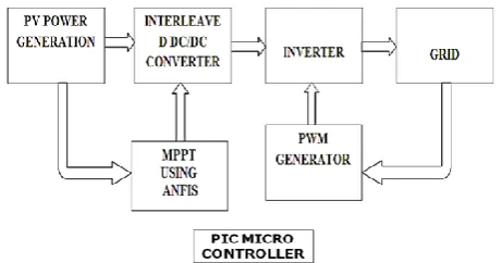
[image:1.595.311.542.402.523.2]The proposed methodology is designed in hardware and the ANFIS MPPT algorithm is added to microcontroller for control of interleaved boost converter output with boost efficiency.The ANFIS MPPT is implemented in PIC microcontroller for improving the dynamic stability of the system in hardware implementation.The rest of the power electronics components used to built the simulated system in a model circuit configuration with desired output efficiency.
Fig. 1 Block Diagram of ANFIS based MPPT controller Block Diagram
II. DESIGN IMPLEMENATATION OF PROPOSED SYSTEM
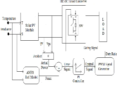
The block schematic of the MPPT consists of PV module, convertor, \ PI controller, signal generator and ANFIS model. For utilizing the ANFIS in a progressively effective and ideal way, we can utilize the best parameters acquired by genetic algorithm. The ANFIS reference model provides out the crisp value from the PV module at a particular temperature and irradiance level. The particular output power from the PV module at a specific temperature and irradiance level is determined on apparent voltage and currents. The powers are thought about and in this way the error is given to a corresponding essential (PI) controller, to get the executives signals.
Analysis of Grid Tied Solar PV System using
ANFIS Algorithm
The response of PI controller is provided to PWM generator, which regulates the PV module by controlling the duty cycle of converter.
A. ANFIS Fuzzy Interface System
An adaptive Neuro-fuzzy inference integrates fuzzy logic and neural networks principles. Its inference system relates to a set of fuzzy IF – THEN rules to approximate nonlinear functions.Hence, ANFIS is considered to be a universal estimator.
[image:2.595.74.262.97.234.2]Associate adaptation Neuro-fuzzy logical thinking system or ANFIS may be a quite ANN that's supported Takagi– Sugeno fuzzy logical thinking system. Hence it integrates each neural networks and logic principles, it's possible to detention the advantages of each in an exceedingly single framework.
Fig. 2 Block of ANFIZ Fuzzy System B. MPPT algorithm
Maximum power point tracking is a method utilized regularly with wind turbines and photovoltaic solar systems to extract maximum power under all conditions.
C. PV solar power system
Renewable Energy sources acquires a growing importance in the world due to its consumption and exhaustion of fossil fuels. The PV solar system is increasingly important and the most readily available source of Renewable energy due to its clean nature , less maintenance and operating without noise. Solar cells convert daylight squarely into power. Solar cells area unit often accustomed management adding machines and watches. They’re product of conductive materials like those utilised in computer chips. At the purpose once daylight is consumed by these materials, the alternative energy thumps electrons free from their particles, sanctioning the electrons to manoeuvre through the fabric to deliver power. This procedure of adjusting over light-weight (photons) to power (voltage) is thought because the electrical phenomenon (PV) impact.
Solar cells area unit often consolidated into modules that hold around forty cells; a number of these modules area unit mounted in PV clusters which will build the grade relating to a number of meters on a facet. These level plate PV clusters are often mounted at a settled purpose attempt south, or they will be mounted on a GPS beacon that takes when the sun, sanctioning them to catch the foremost daylight through the span of multi day. A number of associated PV clusters will provide enough capability to a family unit; for substantial electrical utility or trendy applications, many exhibits are often interconnected to form a solitary, expansive PV framework.
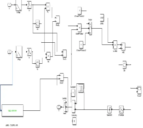
[image:2.595.311.543.283.454.2]III. SIMULATION OF PROPOSED SYSTEM The simulation of proposed system is simulated in MATLAB/Simulink Simulation software. The simulation model of the system is as shown in the figure 3.
Fig. 3 Simulation diagram of proposed system The system consists of PV solar system is also simulated and designed. The simulation model of solar PV system is as shown in the figure 4.
[image:2.595.334.535.527.712.2]International Journal of Innovative Technology and Exploring Engineering (IJITEE) ISSN: 2278-3075, Volume-8 Issue-6S, April 2019
[image:3.595.55.284.94.298.2]The proposed MPPT algorithm consists of hybrid technique called as ANFIS algorithm. The MPPT algorithm is as shown in the figure 5.
[image:3.595.313.538.107.273.2]Fig. 5 Simulation model of proposed MPPT Technique The implemented algorithm is as shown in the figure 6.
Fig. 6 ANFIS algorithm implemented MPPT technique Simulation model
The interleaved boost converter is used to convert DC to DC high output voltage is as shown in modelled as shown in the figure 7.
Fig. 7 Interleaved Boost converter Simulation Model
[image:3.595.59.280.336.501.2]IV. SIMULATION OUTPUT AND RESULTS The proposed system is successfully simulated using MATLAB/Simulink simulation software. The proposed system PV output voltage is as shown in the figure 8.
Fig. 8 PV output Voltage waveform
The proposed system generated the above voltage of about 80 voltage DC output from Solar PV panel.
[image:3.595.318.534.355.497.2]The DC voltage is boosted through interleaved boost converter the output voltage waveform is as shown in the figure 9.
Fig. 9 Interleaved Boost converter output voltage waveform
The MPPT algorithm proposed is as shown in the figure 10. The waveform generated by ANFIS algorithm.
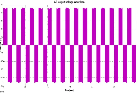
[image:3.595.315.535.565.707.2] [image:3.595.51.287.580.755.2]The boost converter output is fed into the inverter circuit is then converted into AC power. The AC Voltage power is as shown in the figure 11.
Fig. 11 AC output voltage waveform
[image:4.595.308.546.157.381.2]This purposed system is compared with the existing P and O algorithm. The P and O MPPT algorithm output pulse generation for interleaved boost converter is as shown in the figure 12.
Fig. 12 MPPT algorithm output pulse generation of P and O algorithm
Through this output pulse the boosted voltage is very less than the proposed system. The output AC voltage waveform of existing P and O algorithm is as shown in the figure 13.
Fig. 13 AC output voltage waveform of existing system
From the waveforms generated from this section the conclusions are made in the next section.
V. HARDWARE VERIFICATION OF PROPOSED SYSTEM
[image:4.595.56.281.327.521.2]The hardware implementation of proposed system is modelled as shown in the figure 1. The hardware model of the system is as shown in the figure 14.
Fig. 14 Hardware Model of proposed system The system consists of PV solar system is also simulated and designed. The circuit model of interleaved boost converter and inverter is as shown in the figure 15.
Fig. 15 Interleaved circuit model
[image:4.595.309.544.436.679.2] [image:4.595.54.285.603.759.2]International Journal of Innovative Technology and Exploring Engineering (IJITEE) ISSN: 2278-3075, Volume-8 Issue-6S, April 2019
Fig. 16 PIC microcontroller circuit model
[image:5.595.308.544.87.353.2]VI. HARDWARE OUTPUT AND RESULTS The proposed system is successfully designed in hardware with the output generated. The proposed system PV output voltage is as shown in the figure 17.
Fig. 17 PV output Voltage waveform
The proposed system generated the above voltage of about 12 voltage DC output from Solar PV panel. The DC voltage is boosted through interleaved boost converter the output voltage waveform.
The MPPT algorithm proposed is as shown in the figure 18. The waveform generated by ANFIS algorithm.
Fig. 18 MPPT algorithm of Proposed ANFIS algorithm output waveform
The boost converter output is fed into the inverter circuit is then converted into AC power. The AC Voltage power is as shown in the figure 9.
Fig. 9 AC output voltage waveform
PARAMETERS VALUE
SOLAR INPUT DC
VOLTAGE 12 VOLT
OUTPUT AC VOLTAGE 230 VOLT
VII.CONCLUSION
A new method called ANFIS is proposed for efficient solar PV system conversion for connecting it to either load or grid. The simulated solar PV with ANFIS MPPT is designed in hardware model for comparing the simulation results with the hardware results in the same methodology of the proposed system simulation model with the required power electronics components.
From this work, it is proved that the MPPT through ANFIS method has more advantages and also an efficient technique.
REFERENCES
1. S. Sherine, S. Prakash, A. Navaneethamoorthy, “Investigation on Solar
Panels with and Without Shading Effects in Series and Parallel Connections,” International Journal of Engineering and Advanced Technology (IJEAT) , Volume 8 Issue 3, 2019 ,pp. 354 – 357.
2. S. Prakash&K.Sakthivel, “Efficient Transformerless Mosfet Inverter
For Grid-Tied Photovoltic System,” International Journal of Pure and Applied Mathematics, Volume 119, Issue 12, 2018, pp. 7787-7796.
3. G.Hemavathi & S. Sherine, “A Hybrid Power Plant Using Maximum
Power Pointtracking,” International Journal of Pure and Applied
Mathematics, Volume 119, Issue 12, 2018, pp. 8355-8366.
4. D. Mlakić; S. Nikolovski. “ANFIS as a Method for Determinating
MPPT in the Photovoltaic System Simulated in Matlab/Simulink”, 39th
International convention on information and communication
technology, electronic and microelectronic MIPRO 2016, Opatija, Croatia, 2015.
5. “ANFIS as a Method for Determinating MPPT in the Photovoltaic
[image:5.595.61.275.304.484.2] [image:5.595.59.277.577.757.2]