UNIVERSITI TEKNIKAL MALAYSIA MELAKA
DEVELOPMENT OF CRACK ON COMPOSITE DETECTION
SENSOR USING MAGNETIC INDUCTION CONCEPT
This report is submitted in accordance with the requirement of the Universiti Teknikal Malaysia Melaka (UTeM) for the Bachelor of Electronics Engineering
Technology (Telecommunications) with Honours.
by
NURFARAH IZZATI BINTI ISMAIL B071410543
951028065118
DECLARATION
I hereby, declared this report entitled “PSM Title” is the results of my own research except as cited in references.
Signature :
iii
ABSTRAK
iv
ABSTRACT
v
DEDICATION
Special dedicated to
vi
ACKNOWLEDGEMENT
First and foremost, my greatest gratitude to Allah the Almighty, for His will, I managed to complete this study. Thanks a lot for giving me this strength and opportunity to finish this study. Indeed, the lessons learnt gained my knowledge and opened me up to new perspectives. In the name of Allah, most benevolent, ever-merciful, all praises be to Allah, Lords of all the worlds. Thank you Allah.
In this opportunity, I would like to express my heartfelt thanks and sincere appreciation to my supervisor Wan Norhisyam Bin Abd Rashid for his patient guidance and help to me to find out the information to complete this research (Final year project) in the given time. His help and constant encouragement have given me valuable inputs from time to time throughout my study.
vii
TABLE OF CONTENT
Abstrak iii
Abstract iv
Dedication v
Acknowledgement vi
Table of Content vii
List of Tables xi
List of Figures xii
List Abbreviations, Symbols and Nomenclatures xii
CHAPTER 1: INTRODUCTION 1.0 Introduction 1
1.1 Background of project 1 1.2 Problem Statement 2
1.3 Objective 3 1.4 Scope of Project 3 1.5 Thesis Structure 4 CHAPTER 2: LITERATURE REVIEW 2.0 Introduction 5
2.1 Non-destructive Testing (NDT) 5 2.1.1 Visual Inspection 6 2.1.1.1 Types of Discontinuities 6 2.1.2 Radiography 6
2.1.2.1 Types of Discontinuities 7 2.1.3 Ultrasonic 8 2.1.3.1 Types of Discontinuities 9 2.1.4 Eddy Current 10
viii 2.1.5.1 Types of Discontinuities 12 2.1.6 Penetrant Testing 13 2.1.6.1 Types of Discontinuities 13 2.1.7 NDT Methods Used for Evaluation of Materials 14
2.2 Composite 15
2.3 Magnetic Induction Sensor 15 2.3.1 Sensor Electronics 15 2.3.2 Operation of Magnetic Induction Sensors 16
CHAPTER 3: METHODOLOGY
3.0 Introduction 19
3.1 Project flow overview 19 3.2 Overview of the system 22 3.3 Magnetic Induction design at Comsol Multiphysic Software 23 3.3.1 Decide on the representative physics 23 3.3.1.1 Select 2D Axisymmetric as Space Dimension 23 3.3.1.2 Select Magnetic Field as Type of Physics 23 3.3.1.3 Select Frequency Domain as type of study 24 3.3.1.4 Define the geometry on which to solve the problem 25 3.3.1.5 Set the material properties 25
3.4 Sensor model 26
3.5 Bluetooth Electronics Application 26
3.6 Experiment Set-up 27
CHAPTER 4: RESULT & DISCUSSION
4.0 Introduction 28
4.1 Comsol Simulation 28 4.1.1 Relationship between qualities of crack and current value with
types of composite materials. 28
4.2 Hardware Results 33
ix
CHAPTER 5: CONCLUSION & FUTURE WORK
5.0 Conclusion 35
5.1 Significant Contributions towards Process Magnetic Induction Sensor 35 5.2 Recommendations for Future Work 36
REFERENCES 37
x
LIST OF TABLES
2.1 Summary of defects/properties evaluated by NDT
2.2 The existing technology of magnetic induction sensor
2.3 The existing technology of composite detection sensor
4.1 The relationship between distances, types of material and current value.
xi
LIST OF FIGURES
2.1 Principle of radiographic
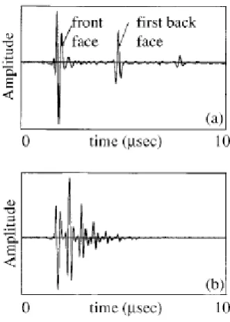
2.2 Ultrasonic ‘A-scan’ of composite material using a normal incidence compression probe
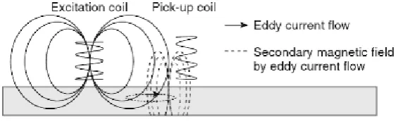
2.3 Schematic diagram of probe and specimen configuration for eddy current testing
2.4 Schematic of principle of MT testing with defect. 2.5 Oscillator circuit
2.6 Cross-section of induction loop sensor made of a multiturn coil wrapped around a permeable core.
3.1 Flowchart of the project 3.2 Block Diagram of the system 3.3 Space Dimension
3.4 Physics Interface 3.5 Study interface
3.6 Graphical User Interface of Comsol Multiphysics. 3.7 Geometry used in Comsol Multiphysics.
3.8 Material used in Comsol Multiphysics. 3.9 Bluetooth Electronics Application 3.10 Experiment Set-up
4.1 Mesh analysis of carbon steel material
4.2 Streamline of magnetic flux density and contour of induced current density for carbon steel
4.3 Mesh analysis of FR4 material
4.4 Streamline of magnetic flux density and contour of induced current density for FR4
xii 4.6 Streamline of magnetic flux density and contour of induced current density
for iron
4.7 Current value based on types of material and distance of the sensor with the material when there is no crack.
4.8 Current value based on types of material and distance of the sensor with the material when there is crack.
xiii
LIST OF ABBREVIATIONS, SYMBOLS AND
NOMENCLATURE
AC - Alternating Current
ADC - Analog to digital converter mm - millimeters
MIS - Magnetic induction sensor MIT - Magnetic Induction Tomography MT - Magnetic particle Testing
NDE - Non-destructive evaluation NDT - Non-destructive technique RC - Resistor-capacitor
1
CHAPTER 1
INTRODUCTION
1.0 Introduction
This chapter presents the overview for overall description for this project. It’s including the background of project, problem statement, objective and scope of study. The thesis structure of the report also state in this chapter for the preview of the report ahead. This will further explain in subtopic below.
1.1 Background of Project
Composites are widely used in high performance products, such as aerospace components or storage tanks. It often exposed to harsh loading conditions. This may lead to crack formation and propagation. However, visible cracking is one aspect that occasionally causes problems and dangers to community. Thus, a numerous crack detection have been develops in the past decades. In previous study, there was an implementation of crack by using various method of non-destructive technique (NDT). NDT have been widely used for evaluating the condition of composite. Visual inspection, radiography, ultrasonic, eddy current, magnetic particle and penetrant testing are the most widely applied NDT techniques.
2 and eddy current concept and was similar to eddy current testing technique of NDT. This project is carried out to show evidence that it is possible to detect crack in composite using magnetic induction concept. The basic principle is that magnetic induction is the process by which a substance, such as iron or steel, becomes magnetized by a magnetic field. According to Bird (2001), electromagnetic induction is when a conductor is moved across a magnetic field so as to cut through the lines of force (or flux), an electromotive force (e.m.f.) is produced in the conductor and causes an electric current to flow round the circuit. Hence an e.m.f (and thus current) is ‘induced’ in the conductor as a result of its movement across the magnetic field. This effect is known as ‘electromagnetic induction’. Eddy currents are loops of electrical current induced within conductors by a changing magnetic field in the conductor, due to Faraday's law of induction.
Magnetic induction sensor (MIS) can be classified as one of the type of non-destructive testing technique. This system is adopted from the Magnetic Induction Tomography (MIT) concept which a new imaging modality that being developed for the process industry and for medical imaging. Magnetic Induction method will be used for fatigue crack detection based on the alternating magnetic field produces around it. The focus of the test is to determine the changing of the current based on different types of composite material. Experimental using magnetic induction concept will be carried out on the not cracked and cracked composite materials to validate the simulation results.
1.2 Problem Statement
3 Sometimes it is difficult to distinguish between crack and not crack in composite material.
1.3 Objective
The goal of this project is to detect crack on composite. The specific objectives that need to be achieved are:
a) To develop a sensor that able to detect crack on composite. b) To make an inspection quality of the composite.
c) To distinguish between crack and not crack on composite material.
1.4 Scope of Project
This project will focus on development of crack on composite detection sensor using magnetic induction concept. The scope of the project have been defined as follows:
a) Develop a sensor to detect any crack in composite.
b) Using Bluetooth Electronic application for inspection whether there are any crack or not in the composite.
4
1.5 Thesis Structure
This report consists of five chapters. The first chapter is an introduction chapter that covers about introduction including background of the project, problem statement, and objective, scope of project and thesis structure of report.
The second chapter provides literature reviews which emphasize on theory magnetic induction, non-destructive testing method that available used in industry to detect crack on composite and some previous research paper related to the project.
The following chapter describes the detailed methodology used in this project. This chapter explains in detail the procedures and steps that have been done to complete this project.
In chapter four, the result and discussion involve are analyzed. This chapter describes the analysis, explanation and discussion of this project.
Lastly, chapter five concludes the outcome of this project and provides some recommendations to improve this project.
5
CHAPTER 2
LITERATURE REVIEW
2.0 Introduction
In this chapter will discuss the literature review of this project. A literature review will provide the review from previous research that is related to this final year project and will discuss a background study related to the project, which includes a fundamental and the history of the creation of the device in order to enhance the understanding of the concept that will be used throughout this research. This project is the new improving technology that is applied to the composite.
2.1 Non-destructive Testing (NDT)
6
2.1.1 Visual inspection
The basic procedure used in visual NDT involves illumination of the test specimen with light, usually in the visible region. The specimen is then examined with eye or by light sensitive devices such as photocells. The equipment required for visual inspection is extremely simple, but adequate illumination is absolutely essential. The surface of the specimen should be adequately cleaned before being inspected (Baldev Raj, 2002, p4). However, Allgaier et al (1993) said that the general advantages of visual inspection techniques of being straight forward and inexpensive may no longer hold. Careful surface cleaning and preparation is required with visual inspection.
2.1.1.1 Types of Discontinuities
a) Surface deposits b) Scaling
c) Erosion d) Discoloration e) Missing parts
2.1.2 Radiography
7 gamma rays, to penetrate objects. In general, the shorter the wavelength, the greater is the penetrating power (Baldev Raj et al, 2002, p55). MR Jolly et al (2015) claimed that radiography involves penetrating the object with short wavelength electromagnetic radiation. The amount of radiation that passes through the object is captured by a detector. The absorption is a function of density and thickness of the material. Cavities and discontinuities lead to a detectable variation in absorption. This statement is parallel with Baldev Raj et al (2008) and Prakash (1980). The advantages of this method are data is presented pictorially and permanent record is created which may be seen at a time and place distant from the test, suitable for thin sections, very sensitivity declared on each film and useful for any material. Radiography is an expensive NDT technique. Thick sections consume a substantial amount of time and energy cost associated is also high (Harara, 2008).
Figure 2.1: Principle of radiographic examination (Baldev Raj et al, 2002)
2.1.2.1 Types of Discontinuities
a) Cracks (parallel to the radiation beam) b) Porosity
c) Material thickness
8
2.1.3 Ultrasonic
Ultrasonic waves are sound waves with frequencies ranges from 500 kHz to 10 MHz. These are more directional than audible sound waves and travel freely in liquid & solid, depending on density and elastic properties of the medium. Ultrasonic waves are widely used for NDT applications that was stated by MR Jolly et al (2015) and supported by Adamowski (2008) which is applicable to most materials, metallic or non-metallic. By this method, surface and internal discontinuities such as laps, seams, voids, cracks, blow holes, inclusions, and lack of bond can be accurately evaluated from one side. The basic technique of ultrasonic inspection is simple: a transducer transforms a voltage pulse into an ultrasonic pulse (wave). One places the transducer onto a specimen and transmits the pulse into the test object. The pulse travels through the object, responding to its geometry and mechanical properties. The signal is then either transmitted to another transducer (pitch-catch method) or reflected back to the original transducer (pulse-echo method). Either way, the signal is transformed back into an electrical pulse, which is observed on a oscilloscope (Peter J. Shull, 2016).
9 example, pipes and storage tanks (Zahran et al, 2002). The advantages of this technique is ultrasonic NDT is a very flexible and robust technique, with applications in a wide range of industries. But ultrasonic techniques do have some disadvantages. First, they require a highly experienced technician. In addition, although noncontacting methods exists, in the majority of cases the transducer must be in contact with the object, though a water or gel coupling layer. Also, ultrasonic waves typically cannot reveal planar flaws (cracks) whose length lies parallel to the direction of wave travel.
Figure 2.2:Ultrasonic ‘A-scan’ of composite material using a normal incidence compression probe: (a) good area; (b) delaminated area (Zahran et al, 2002)
2.1.3.1 Types of Discontinuities
a) Laps
b) Laminations c) Porosity d) Creep
10 f) Intergranular cracks
2.1.4 Eddy current
[image:23.595.179.462.542.630.2]Karbhari (2013) mention that Eddy current technology is a well-established non-destructive method for the characterization of surfaces or material incontinuities by analyzing conductivity and permeability variations. A primary magnetic field is generated when alternating current is applied to an induction coil. Eddy currents are generated in a conductive specimen when the coil is placed near that specimen as in Figure 2.3. Eddy current testing is another important nondestructive evaluation technique used to quickly characterize materials, because eddy currents are influenced by microstructural alterations due to precipitates, cold work, deformation, etc. and the coil impedance or induced voltage in pick-up coil changes accordingly. The magnitude and phase of induced voltage or impedance change are used to correlate with the microstructures and mechanical properties (Tariq, 2012). Like other NDT technique, this method has certain limitations. The major limitations of this method is that only electrically conductive materials can be inspected. Since too many parameters affect the eddy current probe impedance, eddy current testing is not effective when more than one variable is present.
11
2.1.4.1 Types of Discontinuities
a) Electrical conductivity b) Heat treatment condition c) Hardness
d) Cracks e) Voids
f) Porosity g) Corrosion h) Fatigue cracks
2.1.5 Magnetic particle