DESIGN OF MODULAR SMART PICK & PLACE AUTOMATION SYSTEM
SYAHIRAH BINTI MOHD FADZIL
DESIGN OF MODULAR SMART PICK & PLACE AUTOMATION SYSTEM
SYAHIRAH BINTI MOHD FADZIL
This report is submitted
in fulfillment of the requirement for the degree of Bachelor of Mechanical Engineering (Design and Innovation)
Faculty of Mechanical Engineering
UNIVERSITI TEKNIKAL MALAYSIA MELAKA
ii
DECLARATION
I declare that this project report entitled “Design Of Modular Smart Pick And Place Automation System” is the result of my own work except as cited in the references.
iii
APPROVAL
I hereby declare that I have read this project report and in my opinion this report is sufficient in terms of scope and quality for the award of the degree of Bachelor of Mechanical Engineering (Design & Innovation).
iv
ABSTRACT
v
ABSTRAK
vi
ACKNOWLEDGEMENT
Praise to Allah Almighty, that I had successfully finished preparing this ‘Projek Sarjana Muda’ thesis. I wish to express my sincere gratitude to several people that played an important role in the accomplishing of this ‘Project Sarjana Muda’ thesis and I would like to acknowledge them here.
I owe my most sincere gratitude to IR. DR. Tan Chee Fai for his guidance, support, advices and time during the course of my project. I would like to thank DR. Mohd Asri bin Yusuff in taking an effort in reading this thesis and provide good suggestion in perfected this thesis.Special thanks to FKM technicians and lecturers whom are patient in giving me a lot of advice and useful tips in performing the research.
vii
CONTENT
CHAPTER CONTENT PAGE
DECLARATION ii
APPROVAL iii
ABSTRACT iv
ABSTRAK v
ACKNOWLEDGMENT vi
TABLE OF CONTENT vii
LIST OF TABLES x
LIST OF FIGURES xi
LIST OF ABBREVIATIONS xiii
CHAPTER 1 INTRODUCTION 1
1.1 Background 1
1.2 Problem Statement 2
1.3 Objective 2
1.4 Scope Of Project 3
1.5 General Methodology 4
CHAPTER 2 LITERATURE REVIEW 6
2.1 Introduction 6
2.2 TVET system in Malaysia 7
2.3 Type of configuration of pick and place system
8
2.3.1 Polar configuration 10
2.3.2 Cylindrical configuration 11
2.3.3 Cartesian configuration 12
2.3.4 Joint-arm configuration 13
2.3.5 SCARA configuration 14
2.4 Type of end effector 15
viii
2.4.2 Hydraulic gripper 15
2.4.3 Pneumatic gripper 16
2.4.4 Servo-electric gripper 16
2.4.5 Magnetic gripper 16
2.5 Degree of Freedom Robot 17
2.6 Specification of best type 19
2.6.1 Size 19
2.6.2 Mission 19
2.6.3 Speed 20
2.6.4 Simulation 21
2.7 Cost in market 22
CHAPTER 3 METHODOLOGY 23
3.1 Introduction 23
3.2 Product Specification Design (PDS) 26
3.3 Developing morphological chart 27
3.4 Concept selection 29
3.5 Design tools 31
3.6.1 CAD drawing 32
3.6 Design analysis 33
3.6.1 ANSYS structural analysis 33
CHAPTER 4 RESULT AND DISCUSSION 34
4.1 Introduction 34
4.1.1 House of Quality 34
4.1.2 PDS 36
4.1.3 Morphological chart 38
4.1.4 Concept design 39
4.1.4.1 Concept design 1 39
4.1.4.2 Concept design 2 40
4.1.4.3 Concept design 3 41
4.1.4.4 Concept design 4 41
4.1.5 Concept selection 42
4.2 Structure Modeling 44
ix
4.2.2 System description for gripper 47
4.3 ANSYS Structural Analysis 54
4.3.1 Total deformation 58
4.3.2 Maximum shear stress 60
4.3.3 Equivalent stress (Von misses) 61
4.3.4 Factor of Safety 62
CHAPTER 5 CONCLUSION AND RECOMMENDATION 64
5.1 Introduction 64
5.2 Conclusion 64
5.3 Recommendation 65
REFERENCE 66
x
LIST OF TABLES
NO. TITLE PAGES
2.1 Examples of TVET provider in Malaysia 8
2.2 Number of DOF of common joints 18
4.1 HOQ of pick and place system 35
4.2 Symbol of correlation 35
4.3 Product characteristic of design 36
4.4 Morphological chart of pick and place system 38
4.5 Pugh table for concept selection 42
4.6 Description of each part of body 46
4.7 Specification of the system 54
xi
LIST OF FIGURES
FIGURE TITLE PAGE
1.1 Flow chart of general methodology 5
2.1 The five basic robot anatomies 9
2.2 UNIMATE Polar robot 10
2.3 Example of cylindrical robot 11
2.4 Example of Cartesian robot 12
2.5 Example of joint arm robot 13
2.6 Toshiba’s SCARA robot 14
2.7 Degree of freedom of human hand 17
2.8 Typical robot joints 18
2.9 Example of simulation software, courtesy of DENSO Robotics 21
3.1 Project flowchart 25
3.2 Sample of simple morphological chart and the chosen design 28
3.3 Process of Pugh method 29
3.4 Example of Pugh method 30
3.5 Steps on design tools 31
4.1 Concept design 1 39
4.2 Concept design 2 40
4.3 Concept design 3 41
xii
4.5 Best concept 43
4.6 Structure of body 44
4.7 Pick and place system 3d drawing 45
4.8 Unloaded structure 47
4.9 Loaded structure 47
4.10 Condition of gripper when holding curved object 48
4.11 Opened gripper 49
4.12 Closed gripper 49
4.13 Isometric view 50
4.14 Ortographic view 51
4.15 Exploded view 52
4.16 Ballon generation 53
4.17 Free body diagram of the system 54
4.18 Body of pick and place system 56
4.19 Total deformation design 58
4.20 Maximum shear stress design 60
4.21 Maximum shear stress design (close up) 60
4.22 Von misses value of design 61
4.23 Von misses value of design (close up) 61
4.24 Factor of safety at 100kg 62
4.25 Factor of safety at 400kg 62
xiii
LIST OF ABBEREVATIONS
ADTEC Advanced Technological Training Centre BMI British-Malaysian Institute
CAD Computer Aided Design
CC Community College
CIAST The centre for Instructor and Advanced Skill Training GMI German-Malaysian Institute
IKM Institut Kemahiran Mara ITI Industrial Training Institute IKBN Institute Kemahiran Belia Negara
IKBTN Institute Kemahiran Belia Tinggi Negara JMIT Japan-Malaysian Technical Institute KKTM Kolej Kemahiran Tinggi Mara PDS Product design specification Poly Polytechnic
TVET Technical and Vocational Education Training
UC University College
U University
1
CHAPTER 1
INTRODUCTION
1.1 BACKGROUND
Modular is the basic term used that involves a module or modules for basic design construction. The most common or important characteristic of a modular is portable which can be used in various system. Meanwhile, the definition of “smart” in an automation system is the ability of a system to work through the process on its own without the guidance of a human. These robots learn from its environment and experience based on the knowledge, often works on highly repetitive task such as precision packing.
The pick and place automation system is a kind of robot that is used in the industrial world. Nowadays, more robots are used to replace human in the industry. This is because robots can give a much better accurate and efficient work outputs. Moreover, they are very helpful and useful in handling dangerous, dirty or even repetitive dull works. In terms of cost, it is much cheaper compare to human labor in a long term. This is because robots can work overnight without even stopping or get tired. Pick and place automation system is widely used in manufacturing, assembly and packing, mass production of consumer and industrial goods.
2
reducing manpower requirement. Automation is very important especially in rise of technology the in the world economy and daily application. Thus, automation needs to be improved along the way according to customer’s requirement.
1.2 PROBLEM STATEMENT
During the Tenth Plan, mainstreaming and broadening access to quality technical and Vocational Education and Training (TVET) were undertaken to address industry needs for skilled workers. Measures were also undertaken to improve public perception towards TVET. These efforts resulted in the percentage of school leavers pursuing TVET after Sijil
Peperiksaan Malaysia (SPM), increasing from 25% in 2010 to 38% in 2013. Transforming TVET is one of the game changers in the Eleventh Plan to meet the demand of industry and contribute towards economic growth in view of globalization, knowledge economy,
technology advances and global labor mobility. To adapt to TVET, and industrial based training system is needed to train the necessary skills for the TVET student. A modular automation training system that focus on smart pick and place is proposed.
1.3 OBJECTIVE
In the manufacturing industries, smart pick and place automation system is design to help human accomplished difficult task and made the job much easier and decrease the time of production.
3
1.4 SCOPE OF PROJECT
In order to complete this project, scopes are required to assist and guide the
development of this project. The scope should be identified and planned to achieve the objective of the project successfully on time.
The scopes of this project are:
1. Designing the mechanical parts of the pick and place automation system within the criteria of training purpose, easy to fabricate and cost effective.
2. The provision of pick and place automation system is a table size machine and is simple to be handle by students.
4
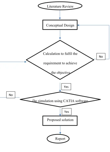
1.5 GENERAL METHODOLOGY
The actions that need to be carried out to achieve the objectives in this project are listed below.
1. Literature review Journals, articles, or any materials regarding the project will be reviewed.
2. The suitable design for smart modular automation pick and place system will be proposed.
3. If the design process of the pick and place system has passed, the calculation process will take place to determine whether the design has fulfilled the requirement needed in the objective.
4. The simulation of the mechanism will be done using CATIA software. The maximum force and the movement of the pick and place system will be tested in the software. 5. The result that was tested will be recorded and be placed to make comparison to further improve the system.
6. Report writing will be done at the end of the project.
5
Literature Review
Conceptual Design
Calculation to fulfil the
requirement to achieve
the objective
Do simulation using CATIA software
Proposed solution
[image:19.595.101.460.89.583.2]Report
Figure 1.1: Flow chart of General Methodology No
Yes
No
6
CHAPTER 2
LITERATURE REVIEW
2.1 Introduction
7
2.2 TVET system in Malaysia
According to Prof. Dr. Jailani et al (2013) the Technical & Vocational Education Training system can be in both private or public institution which provide basic skill training that can be apply through application of mathematics and science. There are five level of qualification which is Certificate, Diploma, Degree, Master and Doctoral. In Malaysia, TVET can be applied by any students at an early age, that is after students have finished their PT3. TVET can gain students by brushing up their basic training skill to a high level mathematics and science. Below are examples of technical and vocation provider in Malaysia for government and private sector.
Level of study
Certificate Diploma First Degree Masters PhD Government :
Ministry of Higher Education
CC, Poly Poly, UC, U UC, U UC, U UC, U
8
MIAT
Private UNIKL,
KLIUC, MMU, UTP, UNITEN,
UNISEL
UNIKL, KLIUC, MMU, UTP, UNITEN,
UNISEL
Table 2.1 : Examples of Technical and Vocational Education and Training Level providers in Malaysia (Source: Prof. Dr. Jailani et al 2013)
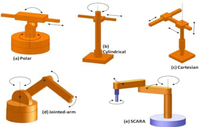
2.3 Type of configuration of pick and place system
[image:22.595.66.529.72.237.2]9
Figure 2.1: The five basic robot anatomies. (Source: A.Modi and M.Patel, 2015)
10
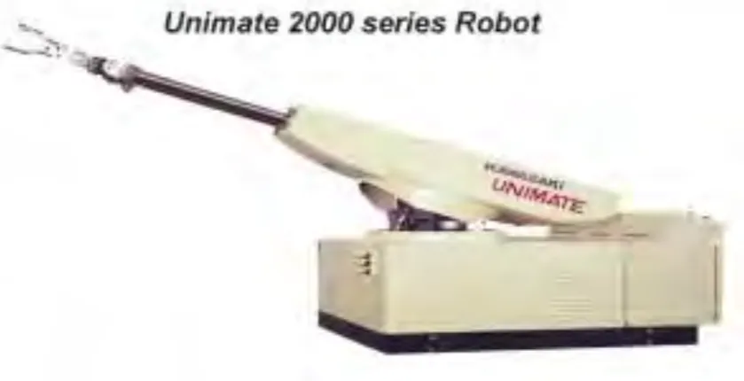
2.3.1 Polar configuration
[image:24.595.92.512.324.539.2]According to R.Shiilling (2013), the polar configuration which also known as spherical configuration, has a concept design similar to the military tank. The robot will move vertically from a pivot point in the middle and can rotate around the axis perpendicular base. Another rod, as the wrist or gripper, will extend and retract to reach for things. According to The Anatomy of Industrial Robot (2011), the advantage of this design is that it is capable of reaching long extended things horizontally. It can do more job than the Cartesian and the cylindrical configurations. Besides that, this design is very simple despite being able to lift heavy weight. Meanwhile, the disadvantage is that the vertical movement is very low and limited. The most common applications of polar configuration are die casting, injection molding, forging, glass handling, material transfer, stacking and unstacking.