White Rose Research Online URL for this paper: http://eprints.whiterose.ac.uk/85764/
Version: Accepted Version
Article:
Long, H., Al-Tubi, I.S. and Martineze, M.T.M. (2015) Analytical and Experimental Study of Gear Surface Micropitting due to Variable Loading. Applied Mechanics and Materials, 750 . 96 - 103. ISSN 1660-9336
https://doi.org/10.4028/www.scientific.net/AMM.750.96
[email protected] https://eprints.whiterose.ac.uk/ Reuse
Unless indicated otherwise, fulltext items are protected by copyright with all rights reserved. The copyright exception in section 29 of the Copyright, Designs and Patents Act 1988 allows the making of a single copy solely for the purpose of non-commercial research or private study within the limits of fair dealing. The publisher or other rights-holder may allow further reproduction and re-use of this version - refer to the White Rose Research Online record for this item. Where records identify the publisher as the copyright holder, users can verify any specific terms of use on the publisher’s website.
Takedown
If you consider content in White Rose Research Online to be in breach of UK law, please notify us by
Analytical and Experimental Study of Gear Surface Micropitting due to
Variable Loading
H. Long
*, I.S. Al-Tubi, M. T. M. Martinze
Departmental of Mechanical Engineering, The University of Sheffield, Sheffield, United Kingdom
*
Corresponding author, email: [email protected]
Keywords: gear micropitting, variable loading, probabilistic analysis, experimental testing, wind turbine gearbox.
Abstract. This paper presents an investigation of the effect of load variation on gear tooth surface
micropitting, for an application in planet gears in a wind turbine gearbox. To study the effect of load variation, two methods are employed: an experimental testing of gear micropitting under variable loading and a probabilistic analysis of gear contact stress and specific lubricant film thickness variations using the ISO Technical Report ISO/TR 15144-1:2010. The load variation of wind turbine gearbox is derived from SCADA (Supervisory Control and Data Acquisition) data recorded in operation. Both experimental and analytical results show that high levels of contact stress, load variations and repeated load cycles are determinant factors for the initiation and propagation of micropitting of gear tooth surfaces.
Introduction
Wind energy plays an increasingly importance role in producing electricity from renewable sources. In 2012 11% of electricity generated in the UK was from renewable sources, 47% of which was produced by wind power [1]. To meet the planned target of enabling wind energy to supply 15% of UK’s electricity by 2020, the capacity for wind power generation is planned to increase in the UK from 5.3 GW to 13 GW onshore and from 2.5 GW to 18 GW offshore by 2020 [2, 3]. To enable wind energy to become a cost competitive energy source, the improvement of wind turbine operational reliability is crucially important especially for offshore operation.
The gearbox is one of the most expensive subassemblies in the wind turbine system. For a 5 MW offshore wind turbine, it contributes to approximately 10% of the wind turbine cost without including transportation costs [1]. Within the wind turbine gearbox, bearings and gears experience high rates of premature failures which cause unplanned wind turbine shutdowns, long down time for repairs and purchase spare parts for replacing the failed components. These reduce wind turbine Availability and increase the Cost of Energy [4]. For offshore operation, this will cause even greater problems due to constrained offshore accessibility because their remote locations and adverse weather conditions
resulting in higher maintenance costs. Investigation into root causes of key gear failure modes will be essential to identify critical operational conditions and important factors affecting the failures. The understanding of these effects on failures will support the future wind turbine gearbox design and operational maintenance to reduce premature failures thus reduces the cost of offshore wind energy.
Gear micropitting and key influencing factors
Micropitting is a Hertzian contact fatigue phenomenon and it is a form of localised material surface damage that occurs under rolling and sliding contact operating in elastohydrodynamic (EHL) or boundary lubrication regimes [5]. Micropitting failure is commonly observed in materials with high surface hardness and it is characterised by the removal of surface roughness asperities and the formation of cavities. Micropits initiate from small, surface or subsurface initial cracks; which are relatively small compared to the size of the contact zone, usually 5–10 µm long and 5–20 µm deep, as shown in Fig. 1 [6], and grow under repeated contact loading cycles [7]. The cracks grow in a shallow angle usually less than 30˚ with respect to the surface, at some point they curve back towards the surface, which in due course will cause the material to break and produced a fractured surface. Continuous loss of material produces a profile deviation for the gear tooth, if continued, it results in reduced gear tooth accuracy, increased loads and noise. If it cannot be restrained, it propagates into macropitting where pits are larger than 1 mm and have irregular shapes or other modes of gear tooth failures such as spalling and scuffing.
Micropitting may occur when peaks of surface roughness asperities contact each other under mixed or boundary lubrication conditions. The main effect of EHD film is to modulate the contact stress distribution in meshing gear surfaces by preventing the direct contact between surface asperity points. However the EHD film does not prevent contact surfaces from cyclic stressing. Low surface roughness or smooth surface finishing and high surface hardness can resist the micropitting [8]. As a result, the assessment of micropitting risk is based on the lubricant film thickness and surface roughness of contact surfaces [5, 9].
[image:3.595.84.523.550.735.2]There are a number of important factors which have a determinant effect on micropitting, these include gear material and surface treatment, surface topography, loading, lubricant, temperature, speed, and relative sliding [10, 11]. Oila and Bull [12] statistically studied seven factors influence micropitting using twin discs to simulate gear tooth contact. Their study concluded that the key factors over the number of load cycles necessary for micropitting occurrence. The more significant contributor was contact stress and micropitting initiated faster at high contact stress and has a significant interaction with surface roughness. Sliding and rolling ratio (SRR) also has a significant effect, the occurrence of surface micropitting decrease at low SRR values; when low temperatures were also observed. For the micropitting propagation rate, propagation is increased at high speed and high SRR. When a high rotational speed is involved micropitting spreads; therefore not much can be done to stop propagation rate at high operational speeds. At a low load, the effect of temperature on micropitting reduces significantly [12].
Analysis of wind turbine gearbox load variation
This paper aims to investigate the effect of variable loading on gear tooth surface micropitting, for an application in planet gears of a wind turbine gearbox. The wind turbine is a megawatt scale machine and has a three-stage gearbox design with one planetary gear stage and two parallel gear stages [13], as shown in Fig. 2. Only planet gears of the low speed shaft (LSS) of the gearbox are studied in this paper because the LSS gears operate under heavy shaft torques and low rotational speeds which are the conditions prone to micropitting damage. During gear meshing, gear tooth surfaces experience rolling and sliding, in the same and opposite directions, as shown in Fig. 3, depending on the contacting tooth’s relative velocities. The occurrence of sliding significantly changes the stress distribution in the surface and sub-surface of gear teeth. Sliding in opposite direction to rolling results in higher stresses because rolling is in one direction and sliding is in the other. At tooth tip and root regions (tooth addendum and dedendum) where the maximum sliding occurs, modified gear tooth profiles are commonly used to reduce contact stress level and to improve stress distribution.
Fig.2 Three-stage wind turbine gearbox design with one planet stage [13]
Fig.3 Gear tooth surface rolling and sliding
Wind turbine gearbox operates under a wide array of highly fluctuating and dynamic load conditions caused by the stochastic nature of wind speed variations and operational wind turbine controls. The exposure of gear tooth surfaces to different loading and rotational speed conditions could cause the lubricant film breaking down resulting in direct metal surface contact. This leads to high surface temperatures due to poor lubrication and high friction between the meshing surfaces.
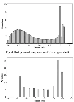
To consider wind turbine gearbox loading and speed variations, the SCADA (Supervisory Control and Data Acquisition) data of 10-minute average of generator power output and generator rotational speed for a period of 2.2 years recorded in an operating wind turbine, are analysed to derive the torque and speed variation ranges and corresponding numbers of occurrences. These analyses are presented as histograms of planet gear shaft torque and rotational speed variations, as show in Fig. 4 and Fig. 5 respectively. The values of planet gear shaft torque and rotational speed are nominalised as torque ratio and rotational speed ratio respectively. For example, the torque ratio is determined by dividing the torque values by the rated torque value of the planet gear shaft. Details of gear parameters, material properties, lubricant properties are given in Al-Tubi and Long (2012) [14]. As can be seen in Figs. 4 and 5, the gearboxes operate near the rated torque and rated rotational speed (the ratio equals to 1.0) for most of the time in operation, as expected. However, the torque ratio histogram in Fig. 4 shows the occurrences of torque values above the rated torque, indicating a probability of overloading. The highest torque ratio of over 1.18 is recorded from the 2.2 years of SCADA data analysed. As shown in Fig. 5, high numbers of occurrences of shaft rotational speed ratios are concentrated between 0.55 and 0.6 and at rated speed ratios. The high torque ratios occur when the power ratio is high and the speed ratio is below the rated rotational speed, indicating that the high torque ratios occur at the transient region between partial load and full load of the generator.
[image:5.595.150.441.374.774.2]Torque ratio P e rc e n ta g e 1.2 1.0 0.8 0.6 0.4 0.2 0.0 10 8 6 4 2 0
Fig. 4 Histogram of torque ratio of planet gear shaft
[image:5.595.154.439.387.566.2]Speed ratio P e rc e n ta g e 1.1 1.0 0.9 0.8 0.7 0.6 0.5 0.4 25 20 15 10 5 0
Gear micropitting analysis method
The gear tooth contact stress and specific lubricant film thickness are determined based on Method B as recommended in the ISO Technical Report of gear micropitting ISO/TR 15144-1:2010 [5]. The local Hertzian contact stress, P , along the path of gear tooth contact is determined according to Eq. 1. The local lubricant film thickness, hY, can be determined by Eq. 2. The specific lubricant film
thickness, , is dimensionless and it is defined as the ratio of the lubricant film thickness, hY, and
the effective mean surface roughness, , of gear tooth surfaces, as shown in Eq. 3. The micropitting safety factor, n, may be defined as the ratio of the minimum specific lubricant film thickness, GF, min,
and the permissible lubricant film thickness, GFP, as shown in Eq. 4.
The prefix Y refers to a specific contact point on tooth flank. More details regarding the calculation methods can be found in the ISO/TR 15144-1 (2010) [5] and Al-Tubi and Long (2012) [14]. Definitions of the parameters used in the equationsare given and calculated using methods provided in the ISO international standards for gears and determined by using recommended values given the ISO datasheets for gears. More details are given in [14].
のびねね ね び ね ぴ ね のば ね はは
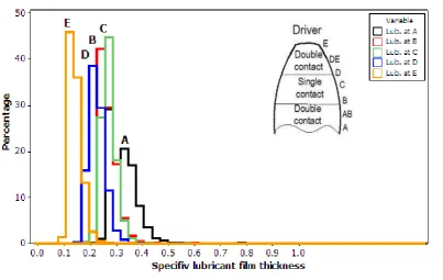
The local contact stress and specific lubricant film thickness at different contact point A, B, C, D and E of tooth flank along the line of action are calculated. The locations of these points, as shown as the insert image in Figs. 6 and 7, are selected based on the suggestion of ISO/TR 15144-1:2010 where the variations of the contact stress and specific lubricant film thickness during single and double tooth contact can be evaluated. The maximum sliding between gear teeth occurs in mesh-in, point A and mesh-out, point E because the difference of velocities of gear teeth is greatest in these regions.
As can be seen in Fig. 6, histograms show that the contact stress at point D varies considerably covering a wide range due to the variation of planet gear shaft torque. The contact stress at point D has a high probability of occurrence within a narrow range from 1530 to 1640 N/mm2. The maximum contact stresses of the gear tooth surface occur at point D (at tooth dedendum), and the minimum values occur at point A (tooth addendum).
Eq. 3 may be used to determine the specific lubricant film thickness if the surface roughness of meshing gears is known. Wind turbine gears require high accuracy and smooth tooth surface finishing to ensure sufficient load capacity and to achieve required service cycles. Such a smooth surface is one of the most important factors in micropitting resistance [13]. It is recommended in the international standard [13] that the maximum mean surface roughness for wind turbine gears should be equal to or less than 0.7 µm.
standard [13]. It reveals that the specific lubricant film thickness is smaller than 1.0 at all contact points, while point E has lowest values at high percentage of occurrences, indicating a high risk of micropitting of the whole gear tooth surface. It is clear that the high level of gear shaft torque and its considerable variation range has contributed to the high level of contact stresses and its variations and these in turn reduce the specific lubricant film thickness, resulting in high risk of micropitting.
Fig. 6 Histograms of contact stress at 5 contact points on gear tooth flank
Fig.7 Histograms of specific lubricant film thickness at 5 contact points on gear tooth flank
Experimental testing of gear micropitting
[image:7.595.100.504.428.683.2]surfaces are obtained by using replica samples of the surfaces and digital image analysis. Fig. 8 shows gear tooth surface micropitting in dedendum (tooth root region), Fig. 8a, and addendum (tooth tip region), Fig. 8b, after completing step-up contact stress levels and corresponding loading cycles as detailed in the figure. The micropitting initiates first at the dedendum at contact stress of 1332 MPa after 16 million cycles then it initiates at the addendum at a higher contact stress of 1452 MPa and load cycle of 24 million cycles. However the micropits on the addendum starts to spread over the tooth surface after the contact stress increases to 1666 MPa with 40 million cycles completed. At the end of test of 56 million cycles, the characteristics of micropits are different on gear tooth dedendum and addendum: the micropits are deeper on the dedendum but shallow micropits spread over the most surface on the addendum. This is because that the profile modification of gear teeth leaves the grinding cutting edges on gear tooth surfaces which may initiate micropitting. The experimental observation reveals that the micropitting can initiate at the dedendum and/or at the addendum.
Max contact stress: 1332 MPa Max contact stress: 1666 MPa Max contact stress: 1855 MPa Completed cycles: 16 millions Completed cycles: 40 millions Completed cycles: 56 millions
Initiation of micopitting Little propagation of mictopits Deep voids of micropits
(a) Tested gear tooth dedendum
Max contact stress: 1452 MPa Max contact stress: 1666 MPa Max contact stress: 1855 MPa Completed cycles: 24 millions Completed cycles: 40 millions Completed cycles: 56 millions
Initiation of micopitting Propagation of mictopits Wide spread of micropits
(b) Tested gear tooth addendum
Fig.8 Micropitting initiation and propagation under different contact stress levels and load cycles
Conclusions
Based on the analytical and experimental results obtained, the following conclusions can be drawn:
2. The specific lubricant film thickness determined by using the ISO/TR 15144-1:2010 and mean gear surface roughness of 0.7m as recommended by the BS EN 61400-4 [13] show there is a high risk of micropitting on the planet gear surfaces of the wind turbine gearbox.
3. Micropitting images of gear teeth obtained from the experiment show that the high contact stress levels and load cycles are determinant factors resulting in the initiation of micropitting and propagation, the cutting edges left on gear tooth surfaces due to profile modifications have also contributed to the micropitting initiation.
References
[1] I. Macleay, K. Harris, A. Annut. Digest of United Kingdom Energy Statistics 2013. In.: Department of Energy and Climate Change, 2013.
[2] UK Renewable Energy Roadmap. In.: Department of Energy and Climate Change, 2011.
[3] UK Renewable Energy Roadmap Update 2012. In.: Department of Energy and Climate Change, 2012.
[4] Y. Feng, P.J. Tavner, H. Long, Early experiences with UK round 1 offshore wind farms, Proceedings of Institution of Civil Engineers: Energy, 163 (4) (2010) 167-181.
[5] BSI Standard Publication, ISO/TR 15144-1: 2010 Calculation of micro-pitting load capacity of cylindrical spur and helical gears, Introduction and basic principles, (2010) 1-56.
[6] J. Zhang, Influence of shot peening and surface finish on the fatigue of gears, PhD Dissertation, University of Newcastle, UK, 2005.
[7] F. Antoine, J. M. Besson, Simplified modellization of gear micropitting, Proceedings of the Institution of Mechanical Engineers, Part G: Journal of Aerospace Engineering, 216(6)(2002) 291-302.
[8] R. L. Errichello, Morphology of micropitting, The Journal of Gear Technology. (2012) 74-81. [9] P.M Ku, Failure modes in gears. In Guichelaar P. J., Levy B. S., Parikh N. M., editors. Gear Manufacture and Performance. American Society For Metals, 1974.
[10] H. Long, A.A. Lord, D.T. Gethin, B.J. Roylance, Operating temperatures of oil-lubricated medium-speed gears: Numerical models and experimental results, Proceedings of the Institution of Mechanical Engineers, Part G: Journal of Aerospace Engineering, 217 (2)(2003) 87-106.
[11] H. Long, G. Zhang, W. Luo, Modeling and analysis of transient contact stress and temperature of involute gears, Chinese Journal of Mechanical Engineering, 40 (8)(2004) 24-29.
[12] A. Oila and Bull, S. J, Assessment of the factors influencing micropitting in rolling/sliding contacts, Wear, 258 (10) (2005) 1510–1524.
[13] BSI Standard Publication, BS EN 61400-4:2013, Wind Turbine, Part 4: Design requirements for wind turbine gearboxes (2013).
[14] I.S. Al-Tubi, H. Long, Prediction of wind turbine gear micropitting under variable load and speed conditions using ISO/TR 15144-1: 2010, Proceedings of the Institution of Mechanical Engineers, Part C: Journal of Mechanical Engineering Science, 227 (9) (2013) 1898-1914.
![Fig. 1 Micropitting characteristics: depth and length of a micropit [6]](https://thumb-us.123doks.com/thumbv2/123dok_us/7893220.186576/3.595.84.523.550.735/fig-micropitting-characteristics-depth-length-micropit.webp)