UNIVERSITI TEKNIKAL MALAYSIA MELAKA
PID AND CASCADE CONTROLLER FOR TRACKING
PERFORMANCE OF XY TABLE BALL SCREW DRIVE
SYSTEM
This report submitted in accordance with requirement of the Universiti Teknikal Malaysia Melaka (UTeM) for the Bachelor Degree of Manufacturing Engineering
(Robotics and Automation)(Hons.)
by
MUHAMMAD NASIRUDIN BIN TAJUDIN B051110232
920609-07-5099
UNIVERSITI TEKNIKAL MALAYSIA MELAKA
BORANG PENGESAHAN STATUS LAPORAN PROJEK SARJANA MUDA
[image:2.595.84.558.331.729.2]TAJUK: PID AND CASCADE CONTROLLER FOR TRACKING PERFORMANCE OF XY TABLE BALLSCREW DRIVE SYSTEM
SESI PENGAJIAN: 2014/15 Semester2
Saya MUHAMMAD NASIRUDIN BIN TAJUDIN
Mengaku membenarkan Laporan PSM ini disimpan di Perpustakaan Universiti Teknikal Malaysia Melaka (UTeM) dengan syarat-syarat kegunaan seperti berikut:
1. Laporan PSM adalah hak milik Universiti Teknikal Malaysia Melaka dan penulis. 2. Perpustakaan Universiti Teknikal Malaysia Melaka dibenarkan membuat salinan untuk
tujuan pengajian sahaja dengan izin penulis.
3. Perpustakaan dibenarkan membuat salinan laporan PSM ini sebagai bahan pertukaran antara institusi pengajian tinggi.
4. **Silatandakan ( ) SULIT
TERHAD
TIDAK TERHAD
(Mengandungi maklumat yang berdarjah keselamatan atau kepentingan Malaysia sebagaimana yang termaktub dalam AKTA RAHSIA RASMI 1972)
(Mengandungi maklumat TERHAD yang telah ditentukan oleh organisasi/badan di mana penyelidikan dijalankan)
AlamatTetap:
NO.32, Lintang Tenggiri
Seberang Jaya
13700 Perai, Pulau Pinang
Tarikh: ________________________
Disahkan oleh:
Cop Rasmi:
Tarikh: _______________________
DECLARATION
I hereby, declared this report entitled “PID and Cascade Controller for Tracking Performance of XY Table Ball Screw Drive System” is the results of my own
research except as cited in references.
Signature : ……….
Author’s Name : MUHAMMAD NASIRUDIN BIN TAJUDIN
APPROVAL
This report is submitted to the Faculty of Manufacturing Engineering of UTeM as a partial fulfillment of the requirements for the degree of Bachelor of Manufacturing Engineering (Robotics & Automation) (Hons). The member of the supervisory is as follow:
i
ABSTRACT
ii
ABSTRAK
iii
DEDICATION
First of all I will dedicated to Allah S.W.T, The Almighty God who gave his strength and knowledge for completing my Final Year Project (FYP)
To my beloved parents, Mr. Tajudin Bin Hamzah and Mrs. Nazirah Binti Md Noordin for their understanding and support morally and financially.
To my siblings Mohd Nazarudin Bin Tajudin and Mohd Amiruddin Bin Tajudin for their enternal love and support.
iv
ACKNOWLEDGEMENT
This final year project (FYP) research would not have been possible without the support of many people. I would like to take this opportunity to express profound gratitude and deep regards to my supervisor, Ir. Dr. Lokman Bin Abdullah for his guidance and constant encouragement throughout this two whole semester while the FYP was done. Ir. Dr. Lokman had given me valuable information and guidance, which helped me in completing this FYP research and thesis.
Besides that, I would like to express a deep sense of gratitude to the entire control system group in the computer integrated manufacturing (CIM) lab. The cooperation, dedication and knowledge received from all the members of control system team that were vital for the success of my final year project.
Then I also want to thanks Universiti Teknikal Malaysia Melaka and Faculty of Manufacturing Engineering for given me the opportunities to gain experience and knowledge of researching a project for two semesters.
v
TABLE OF CONTENT
Abstract i
Abstrak ii
Dedication iii
Acknowledgement iv
Table of Content v
List of Tables viii
List of Figures ix
List Abbreviation, Symbol and Nomenclatures xi
CHAPTER 1: INTRODUCTION 1
1.1 Background 1
1.2 Problem Statement 2
1.3 Objectives 2
1.4 Scope 3
1.5 Organization of Report 3
CHAPTER 2: LITERATURE REVIEW 4
2.1 Introduction 4
2.2 State of the Art on Control in Machine Tool 5
2.2.1 Mechanical Drive System 5
2.2.2 Disturbance in Drive System 9
2.2.1.1Friction Force 9
2.2.1.2Cutting Force 10
2.3 Good Tracking Performance – A Controller Design Approach 11
2.3.1Controller Design 11
2.3.1.1Controller Design Based On PID 11
2.3.1.2Other Technique of Controller Design 12
vi
CHAPTER 3: METHODOLOGY 13
3.1 Introduction 13
3.2 Experimental Setup 17
3.3 System Identification and Modelling 19
3.4 Motor Constant Identification 21
3.5 Summary 22
CHAPTER 4: RESULT & DISCUSSION 23
4.1 Introduction 23
4.2 PID Controller 24
4.2.1 PID Control Structure and Configuration 24
4.2.2 Design of PID Controller 25
4.2.3 Analysis: Validation of PID controller through simulation 29 and experiment work
4.3 Cascade P/PI Controller 31
4.3.1 Cascade P/PI Control Structure and Configuration 31
4.3.2 Design of Cascade P/PI Controller 33
4.3.2.1.Design of PI Velocity (Inner) Controller based on 33 Measured FRF
4.3.2.2.Design of P Position (Outer) Controller based on 38 Measured FRF
4.3.3 Analysis: Validation of Cascade P/PI controller through 42 simulation and mathematical model
4.4 Result 44
4.4.1 Maximum Tracking Error 44
4.4.1.1Simulation 44
4.4.1.2Experimental and Mathematical Model 49
4.4.2 Root Mean Square Error (RMSE) 54
4.5 Discussion 55
4.5.1 Discussion on Maximum Tracking Error 55
4.5.2 Discussion on Root Mean Square Error (RMSE) 56
vii
CHAPTER 5: CONCLUSION & FUTURE WORK 58
5.1 Conclusion 58
5.2 Future Work 60
REFERENCES 62
APPENDIX A 65
APPENDIX B 66
APPENDIX C 69
APPENDIX D 71
viii
LIST OF TABLES
3.1 Gantt Chart of The Project 16
3.2 The Parameter for X and Y axes of System Model 20
4.1 PID controller gain value 25
4.2 Gain and phase margin of PID control for X-axis using FRF system 26 4.3 Bandwidth at close loop and sensitivity for X-axis using FRF system 28
4.4 PI controller gain for speed loop 34
4.5 Gain and phase margin of PI control for X-axis using FRF system 35 4.6 Bandwidth at close loop and sensitivity (Velocity Loop) for X-axis 37 4.7 Gain and phase margin of P control for X-axis using FRF system 39 4.8 Bandwidth at close loop and sensitivity (Position Loop) for X-axis 41
4.9 The configuration used in finding result 44
4.10 Simulation maximum tracking error and percentage error 48 4.11 Experiment/mathematical model maximum tracking error & error (%) 51 4.12 RMSE and percent error reduction at 1 mm and 15 mm amplitude 54
ix
LIST OF FIGURES
2.1 Example of Basic Rack and Pinion Drive System 6
2.2 Example of Basic Ball Screw Drive System 7
2.3 The Example of Iron Core for the Linear Drive System 8
2.4 Example of Piezoelectric Drive Actuator 8
3.1 Flow Chart of Research Methodology 14
3.2 The XY Table Ball Screw Drive System 17
3.3 The Schematic Overall Process of Experimental Setup 18 3.4 Example of Simulink Diagram of FRF Measurement 19
3.5 The X and Y Axis FRF Measurement 20
3.6 Example of Block Diagram to Approximate the Force Constant 21
4.1 General control structure of a PID overall controller 24 4.2 Open loop bode diagram for X-axis using FRF system 26 4.3 Closed loop bode diagram for X-axis using FRF system 27 4.4 Sensitivity bode diagram for X-axis using FRF system 27 4.5 Open loop nyquist diagram for X-axis using FRF system 29 4.6 Simulation PID X-axis maximum tracking error 1mm amplitude 30 4.7 Experiment PID X-axis maximum tracking error 1mm amplitude 30 4.8 General Control structure of a Cascade overall controller 31
4.9 Ideal Cascade control for position control 32
xi
LIST OF ABBREVIATIONS, SYMBOLS AND
NOMENCLATURE
AC - Alternate Current
CNC - Computer Numerical Control
DC - Direct Current
DSP - Digital Signal Processing FFT - Fast Fourier Transform FYP - Final Year Project
FRF - Frequency Response Function - System Model Transfer Function
I/O - Input/Output
Kf - Motor Constant
PID - Proportional, Integral, Derivative PI - Proportional, Integral
PD - Proportional, Derivative
P/PI - Proportional/Proportional, Integral MIMO - Multiple Input Multiple Output ZPTEC - Zero Phase Tracking Error Controller RMSE - Root Mean Square Error
RMS - Root Mean Square PSM - Projek Sarjana Muda SISO - Single Output Single Input LTI - Linear Time Invariant DAC - Digital to Analog NLLS - Nonlinear Least Square
xii
V - Voltage
sec - Seconds
1
1.1 Background
The advancement of technologies boosts the need for accuracy, robustness, speed and quality of the product in machine tool industries. However, the existing of disturbance in machine tool system will lead to the in accuracy and poor surface finish of the product produce. In general, there are two type of disturbance, one is cutting force and the other is friction force. Therefore this project is focusing on accuracy in tracking performance.
The cutting force is produce from the contact in between the cutting tool and the work piece, thus it exist in nature of the milling process and it simply be refrain from it (Abdullah et al., 2012). As stated by Kalpakjian et al. (2013), the cutting force is determined by the milling parameters such as the depth of cut and spindle speed.
XY Table is a basic structure of CNC machine. It has been widely use in machine tool industries. Good examples of CNC machine are work feeder of CNC lathe, CNC milling and drill press. In general, XY table consist is X-axis and Y-axis motion, where each motion axis is driven by individual actuator such as DC servomotor through high precision ball screw (Patrick et al., 2012).
According to Chiew et al. (2012), the PID controller are applied in many industrial uses such as temperature control of refrigerator and air conditioning system. Its flexibility allowed the benefits from the improvement of technology. The PID
2 controller is the combination of PI and PD controller that improve both steady state error and transient response.
1.2 Problem Statement
As the technology advance into a new era, the constant need of high accuracy, robustness and speed in machine tool have trigger the development of advance technologies to compensate the weakness in the traditional machine. The machining problem in terms of high disturbance force and tracking performance in term of lower maximum tracking error and root mean square error (RMSE) have reduce the quality of the product produce. There are two types of disturbance force namely cutting force disturbance and friction force disturbance. Today, computer numerical control machine or also known as CNC machine is a machine that can easily produce metal product into the designed shape. This machine play major role as it is been widely used in manufacturing industries. XY table is basic structure of CNC machine that used propagate the material for machining. Since there is a need for improving the tracking performance of a machine tool, therefore in order to obtain high accuracy, robustness and speed in machine tool to reduce the disturbance force, it is a must to design a suitable controller to compensate those disturbance forces.
1.3 Objective
The objectives of this research project are:
i. To propose and design parameters of the control strategy for tracking performance of the system.
3 iii. To analyse and compare the effectiveness of the PID controller and Cascade
P/PI in term of tracking performance.
1.4 Scope
The research project scopes are:
(a) Using only PID controller and Cascade P/PI controller. (b) Using only X-axis of XY table ball screw drive system.
(c) Amplitude used are 1 mm and 15 mm and frequency used of 0.7 Hz.
(d) The tracking performance of XY table ball screw drive system are compared based on tracking error and root means square error (RMSE)
1.5 Organization of Report
The research report is organized as stated:
(a) Chapter 2 included the literature review of mechanical drive system, disturbance forces and controller design approach of the drive system for the machine tools.
(b) Chapter 3 consist of methodology in this research project. The methodologies are flow chart and Gantt chart, experimental setup, system identification and system modelling and also motor constant identification.
(c) Chapter 4 describe and further discuss on the controller design, analysis, validation and result of PID controller and Cascade P/PI based on maximum tracking error and also root mean square error (RMSE).
4
2.1 Introduction
Nowadays, in machine tool society, the high accuracy and robustness characteristic are the aim of the positioning system in the machine tool for accommodating against various disturbance force (Abdullah et al., 2013). To realise this needs, the specific controller are design especially for the machine tool. One of the item that can add to the high accuracy and robustness is the tracking performance of it drive system. The presence of the disturbance force can further cause inaccuracy in tracking and positioning (Abdullah et al., 2012). Disturbance forces are classified as cutting force and friction force. In order to improve the tracking performance the controller need to compensate one of the disturbance forces that is cutting force.
In this chapter, the information regarding the study are provided. Firstly, the state of art on motion control of machine tool are discussed in section 2.2 that covers the mechanical drive system in section 2.2.1 and disturbance in drive system in section 2.2.2. Then in section 2.3 the method of getting a good tracking performance by using controller design approach is discussed thoroughly. Lastly in section 2.4 the summary of the literature review is stated.
5
2.2 State of the Art on Control in Machine Tool
Entering this modern era, the mechanical drive system have advanced into latest technology with a higher demand. This advancement of drive systems are needed to counter the demand of high speed, precise positioning and tracking performance. As this situation happen, the task become more challenging to strive for a better tracking system. In general, the state of the art of control in machine tool section will discuss about the chronological change in mechanical drive system and also about the disturbance force and the ways to compensated it.
2.2.1 Mechanical Drive System
The evolution of the mechanical drive system have replace the use of old type of drive system that is rack and pinion with more advance mechanism of direct drive such as piezoelectric drive system and also linear drive system. This event have offers the manufacturing industries the speed and precision of machine that they needed to produce a higher quality product with shorter time.
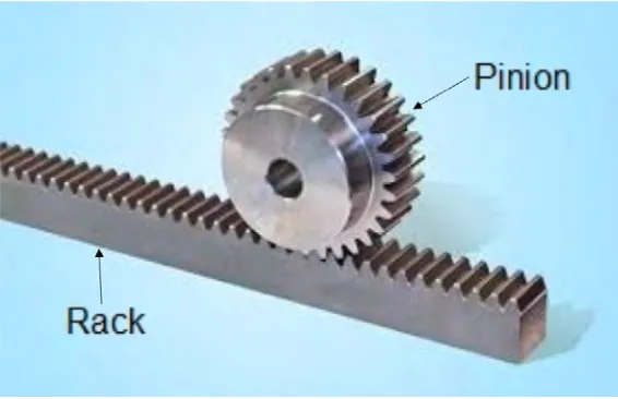
First is the rack and pinion drive system. It have a pair of circular gear that been calledpinion and also a linear gear that is called as a rack and it function to transform rotational motion into linear motion, as shown in Figure 2.1 (Abdullah, 2014). According to Altintas et al. (2011), the rack and pinion drives are suitable for longer distance of feed travel and to realize it the several racks must be combine together.
6
Figure 2.1: Example of Basic Rack and Pinion Drive System
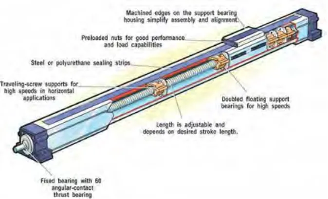
Next is the ball screw drive system that is been shown in Figure 2.2. Ball screw drive system is the main drive system that been used by the XY table in this research. This conventional type of this drive structure is a type of transmission mechanism that used to converts motion of motor from rotary motion to linear motion and it consist of gearing elements and the lead-screw (Jamaludin, 2008).
7
Figure 2.2: Example of Basic Ball Screw Drive System
Third drive system is linear drive system. According to Jamaludin (2008), the linear motor with direct drive technique or simply known as linear drive system is the improvement of the ball-screw drives system as it has no mechanical transmission between motor and load thus eliminate friction and backlash that are normally present in the transmission mechanisms such as gear boxes, harmonic drives and rack-and-pinion systems. In addition, the total system friction also been lowered in guide ways. This also gives better tracking performance as the transmission errors are gone.
8
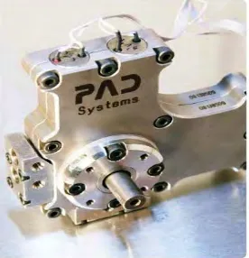
Figure 2.3: The Example of Iron Core for the Linear Drive System
[image:24.595.251.389.531.674.2]The fourth mechanical drive system is piezoelectric drive system. In micro-machining sectors, piezoelectric actuators became an important component as it can supply a higher force and high stiffness of movement with nano-scale resolution but restricted by it minimum travelling distance (Elfizy et al., 2004). According to Abdullah (2014), there is a large number of exposed ceramic discs that is coated with flexible insulation material in the fundamental of the assembled type of piezoelectric actuator to give a better dynamic performance for actuating the movement of the XY Table. The general theory of piezoelectric actuator shown in Figure 2.4 is the ability to produce a large force by generating electric charge in response to be applied in mechanical loads to drive the locomotion of the system.