Abstract— Disturbance forces acting on a system can greatly
influence both positioning and tracking accuracy. This is especially important in machining process such as milling process. This paper is focused on the compensation of cutting forces in a XY high speed milling table using a sliding mode control (SMC). The performance of the sliding mode controller is then compared with a classical PID controller as a mean of comparing its effectiveness. Actual cutting forces for different depth of cuts and spindle speeds are applied in the numerical analysis. These are collected from several milling experiments using a Kistler dynamometer and analyzed further using Fast Fourier Transformation (FFT) for spectral analysis purposes. The PID controller is designed based on open loop and closed loops criteria. Chattering phenomenon on the sliding mode control is addressed by substituting the signum function with a sigmoid-like function. The numerical analysis showed that the robust sliding mode controller is able to compensate for different disturbance forces while suppressing chattering effect.
Index Term— Accuracy, Cutting force, Machine tools, Sliding
mode
I. INTRODUCTION
HIGH accuracy and precision is crucial in machining processes due to sky-rocketing development of technologies and needs. However, the presence of disturbance forces in machining process leads to inaccuracy in positioning and tracking. One of the disturbance forces that greatly affect
T his work was financially supported by the Fundamental Research Grants Scheme (FRGS), Ministry of Higher Education, Malaysia, with
reference number of FRGS/2010/FKP/T K02/5 F00103 . T . H. Chiew is with the Department of Robotics and Automation, Universiti T eknikal Malaysia Melaka, Hang T uah Jaya, Durian T unggal, 76100 Melaka, Malaysia (phone: 6016-6928552; fax: 606-3316430;
e-mail: [email protected]).
Z. Jamaludin is with the Department of Robotics and Automation, Universiti T eknikal Malaysia Melaka, Hang T uah Jaya, Durian T unggal,
76100 Melaka, Malaysia (phone: 606-3316434; fax: 606-3316430; e-mail: [email protected]).
A. Y. Bani Hashim, K. J. Leo, L. Abdullah and N. A. Rafan are with the Department of Robotics and Automationt, Universiti T eknikal Malaysia Melaka, Hang T uah Jaya, Durian T unggal, 76100 Melaka, Malaysia (e-mail: [email protected]; [email protected];
[email protected]; [email protected]).
the tracking performance is cutting forces.
Cutting force is the nature of the milling process and cannot be avoided as it is generated from the interaction between the cutting tool and the work piece. According to [1], cutting force is influenced by the milling parameters such as the depth of cut and spindle speed.
In literature, problem regarding cutting force in milling process have been studied extensively and many controllers have been proposed and validated. The cutting force is compensated using state observer in [2] while the techniques of inverse-model-based observer and repetitive controller in compensating synthesized cutting forces are compared in [3]. As cutting forces are difficult to be estimated or calculated [1], some techniques are demonstrated and validated in literatures to compensate the cutting forces adaptively by integrating the artificial intelligent algorithms. In [4], the active magnetic bearing and fuzzy logic algorithm in self-tuned feedback loop is applied while the feedforward approach with neural network is integrated [5] to compensate the cutting forces adaptively based on the changes of milling parameters.
The classical PID controller is widely known in many industrial applications such as temperature control of refrigerator [6] and air conditioning system [7]. Its flexibility allowed benefits from the advances of technolog y. It is the combination of PI and PD controller which can improve both steady state error and transient response [8].
Sliding mode control (SMC) is a popular robust and nonlinear control method [9] based on variable control structure control. Reference [10] applied sliding mode control in electromechanical systems and have proven that sliding mode is efficient in controlling complex high order nonlinear dynamic plants that operating under uncertainty conditions. The efficiency of SMC and SMC observer in co ntrolling nonlinear dynamic plants with unknown disturbances also is demonstrated in [11]. The application of SMC in robotic manipulators [12] and vessel dynamic positioning system [13] to improve tracking performance and robustness clearly showed the novelty of SMC in improving tracking performance. In addition, SMC is applied by [14] in high speed drive system to reduce contour tracking error while [15] compensated friction force, that is, one of the disturbance forces using SMC. The ability of SMC with d isturbance recovery in dynamic stiffness enhancement of direct -driven
Analysis of Tracking Performance in Machine
Tools for Disturbance Forces Compensation
using Sliding Mode Control and PID Controller
machine tools also had been presented in [16].
Although sliding mode control exhibited robustness and high disturbance rejection capability, it has a major drawback known in the forms of chattering phenomenon, Many methods have been suggested in literature [10], [17] such as boundary layer solution, observer-based solution, and state-dependent gain method to solve the chattering problem. Another approach that introduced in literature is by increasing the order of sliding mode control from first order to higher order and the effectiveness of this approach is proven by [18] and [19]. In this paper, a PID controller and a sliding mode controller are designed, implemented and validated to comp ensate for varying cutting force during milling process in direct -driven machine tools.
II. EXPERIMENT AL SET UP
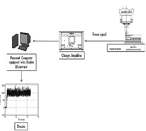
A. Identification of cutting forces characteristics The experimental setup of equipment is shown in Fig. 1.
Fig. 1. Schematic diagram of experimental setup for identification of cutting force characteristics.
End milling cutting processes are performed on conventional milling machine to collect the actual cutting force. In this experiment, Kistler dynamometer type 9257B is mounted on the milling table of Bridgeport 2J2 milling machine to collect cutting forces components in both x and y directions.
Based on Fig. 1, the cutting force signal is amplified by charge amplifier and sent to the personal computer equipped with Kistler Dynoware software. Spindle speed (S) and depth of cut (D) of the milling process are varied in order to establish different characteristics of the cutting forces. These parameters are tabulated in Table I.
TABLE I
MILLING P ARAMETERS OF CUTTING P ROCESS CHARACTERIZATION
Parameters S (rpm) D (mm) Spindle speed test 1000 1.0
1500 1.0 2000 1.0 Depth of cut 1000 1.0 1000 1.5 1000 2.0
.
B. System setup
System used for numerical validation is a linear-drive based XY feed table of a high speed milling machine shown in Fig. 2.
Fig. 2. Linear-driven XY feed table of high speed milling table.
The milling table consists of two axes and these axes are driven by three ETEL’s LMC 22-070-3TA linear motors. Both axes are equipped with a 0.25 µm resolution Heidenhain LF 481C linear encoder.
III. CUTTING FORCE IDENTIFICATION AND ANALYSIS
The work piece used is aluminum block and it is mounted on the dynamometer. High speed steel cutter of diameter 10 mm with four edges is used to cut the material. In order to identify the frequency content of the cutting forces, the collected cutting forces are converted from time domain to frequency domain using Fast Fourier Transform (FFT) method [20]. In frequency domain graph, the data captured is separated to respective frequency content. A sample of the results is shown in Fig. 3.
Fig. 3. Example of transformation of time domain data into frequency domain data via FFT method.
0 5 10 15 -50 0 50 100 150 Time (s) F or ce ( N )
(a) Down milling: 1000rpm, 1mm
0 50 100 150 200 0 5 10 15 20 Frequency (Hz) F or ce ( N )
0 5 10 15
-50 0 50 100 150 Time (s) F or ce ( N )
(b) Down milling: 1500rpm, 1mm
0 50 100 150 200 0 5 10 15 20 Frequency (Hz) F or ce ( N )
0 5 10 15
-50 0 50 100 150 Time (s) F or ce ( N )
(c) Down milling: 2000rpm, 1mm
0 50 100 150 200 0 5 10 15 20 Frequency (Hz) F or ce ( N )
Fig. 4. Graph of cutting force when spindle speed is (a) 1000 rpm, (b) 1500 rpm, and (c) 2000 rpm with constant depth of cut of 1.0 mm.
0 5 10 15
-50 0 50 100 150 Time (s) F or ce ( N )
(a) Down milling: 1000rpm, 1mm
0 50 100 150 200 0 5 10 15 20 Frequency (Hz) F or ce ( N )
0 5 10
0 100 200 300 Time (s) F or ce ( N )
(b) Down milling: 1000rpm, 1.5mm
0 50 100 150 200 0 10 20 30 40 50 Frequency (Hz) F or ce ( N )
0 5 10
0 100 200 300 400 Time (s) F or ce ( N )
(c) Down milling: 1000rpm, 2mm
0 50 100 150 200 0 20 40 60 Frequency (Hz) F or ce ( N )
Fig. 5. Graph of cutting force when depth of cut is (a) 1.0 mm, (b) 1.5 mm, and (c) 2.0 mm with constant spindle speed of 1000 rpm.
Results shown in Fig. 4 indicate lower cutting forces for increasing spindle speed while higher cutting forces are produced for larger cutting depth constant. This is consistent with the fact that greater cutting forces are required to remove greater amount of material.
IV. DESIGN OF CONTROLLERS
Two controllers namely; PID controller and sliding mode control (SMC) are designed based on the identified system shown in Fig. 2. The second order dynamic behavior of the system:
,
8
.
0
20
6
916
.
8
)
(
)
(
2
s
s
e
s
U
s
Y
(1)where Y is the position in the unit of micrometer and U is the input signal in the unit of voltage.
A. PID Controller
The general transfer function of the PID controller, Gc (s) is
showed in (2).
,
)
(
K
s
s
K
K
s
G
c
p
i
d (2)where Kp, Ki and Kd are the gain values for proportional (P),
integral (I) and derivative (D) components of the controller. The controller is designed based on traditional open loop
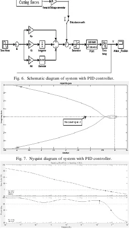
shaping followed by closed loop tuning. Fig. 6 shows the schematic diagram of the PID controller. The parameters of this controller are designed and tuned based on the universal rule of phase margin and gain margin. Nyquist and Bode diagram of open loop transfer function as shown in Fig. 7 and Fig. 8 are plotted to check for stability. Step response and Bode diagram of closed loop transfer function is used to check the transient response behavior and bandwidth of the system. The gain value obtained for Kp, Ki and Kd are 0.01979 V/µm, 0.01969
V/µm·s and 9.8467e-5 V·s/µm respectively.
Fig. 6. Schematic diagram of system with PID controller.
Fig. 7. Nyquist diagram of system with PID controller.
Fig. 8. Open loop transfer function where gain margin is 8.36 dB at frequency of 367 Hz and phase margin is 45.2 degree at frequency of
142 Hz.
B. Sliding Mode Control
and its time derivative. The general formula is shown in (3) and (4).
;
)
,
(
1
e
dt
d
e
e
s
n
(3)).
(
)
(
)
(
t
y
t
r
t
e
(4)Equation (5) showed formula for a second order system, n = 2,
,
)
,
(
e
e
e
e
s
(5)where r(t) is the desired position, y(t) is the actual position and 𝝀 is a positive constant.
In control laws, it consists of a signum function and the equivalent control that includes acceleration and velocity feedforward as shown in (6).
).
(
)
(
t
u
K
sign
s
u
equivalent
(6)where K is positive constant or gain value.
In overall design, both switching function and control laws are combined. At the moment reaching the sliding surface and sliding motion, the switching function is equivalent to zero and achieved stability as shown in (7). The dynamics during sliding are shown in (8) and (9).
,
0
)
,
(
e
e
e
e
s
(7),
0
)
,
(
e
e
e
e
s
(8).
r
y
e
(9)Equivalent control input signal is obtained by converting (1) into differential equation, as well as combining it with (8) and (9):
.
6
916
.
8
8
.
0
20
e
e
r
y
y
u
equivalent
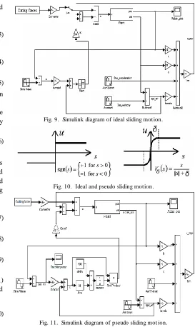
(10)The equivalent control maintains the sliding motion and the proportional gain K ensures that the states are attracted to and remained in sliding surface in finite time. Fig. 9 shows the Simulink diagram of an ideal sliding mode controller. The discontinuous signum function in (6) however, causes high frequency switching and lead to chattering phenomenon. The following proposed sigmoid-like function is used as a substitute to the discontinuous signum function:
,
)
(
s
s
s
V
s (11)where δ is a positive constant that represents the degree of continuous approximation as shown in Fig. 10. The substitution of sigmoid-like function shifted the ideal sliding mode controller to pseudo sliding mode controller as shown in Fig. 11.
Fig. 9. Simulink diagram of ideal sliding motion.
Fig. 10. Ideal and pseudo sliding motion.
Fig. 11. Simulink diagram of pseudo sliding mot ion.
V. EXP ERIMENTAL RESULTS
Numerical validation of tracking performances based on schematic diagram shown in Fig. 6, Fig. 9 and Fig. 11 are conducted using reference sinusoidal signal of amplitude of 30 mm and at 5 rad/s in frequency.
0 2 4 6 8 10 -1
-0.8 -0.6 -0.4 -0.2 0 0.2 0.4 0.6 0.8 1
Time (s)
C
on
tr
ol
in
p
u
t
(V
)
(a) Ideal Sliding Motion
0 2 4 6 8 10
-1 -0.8 -0.6 -0.4 -0.2 0 0.2 0.4 0.6 0.8 1
Time (s)
C
on
tr
ol
in
p
u
t
(V
)
(b) Pseudo Sliding Motion
Fig. 12. Comparison of control input between (a) ideal sliding motion and (b) pseudo sliding motion.
The ideal sliding motion consists of high frequency switching and produced “dirty” control input signal while the pseudo sliding motion resulted in a smoother control input signal. Smoother input proved the reduction of chattering phenomenon and is preferred in real time application.
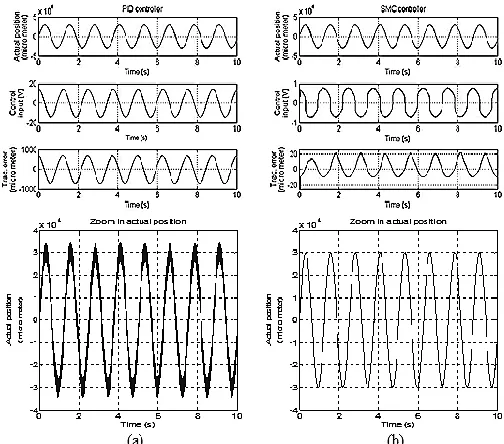
B. Comparison of PID and SMC controller
Control input signals and tracking errors are recorded for analysis. Results obtained for pseudo sliding motion are used in the comparison as it is preferable in real time application due to its ability in chattering reduction. Fig. 13 shows the control input signals and tracking errors of both PID and SMC controllers without presence of cutting forces. Based on Fig. 13, it is clearly shows that the SMC controller provided excellent results in control input and tracking error compared to PID controller. SMC controller maintained the tracking error in the range of ± 15 µm tracking error for PID controller is in the range of ±1000 µm.
Fig. 13. Resutls of (a) PID controller and (b) SMC controller without the presence of cutting forces.
On the other hand, Fig. 14 and Fig 15 show the results in the presence of varying cutting forces.
Fig. 14. Control inputs signals and tracking errors for (a) PID controller and (b) SMC controller with cutting forces generated at various spindle
speed (S).
Fig. 15. Control input signals and tracking errors for (a) PID controller and (b) SMC controller with cutting forces generated at various depth of
cut (D).
Results shown in Fig. 13 to Fig. 15 clearly show better performance for the SMC controller compared to the PID controller. SMC controller provided high robustness and maintained the tracking errors within range of ±25 µm and control inputs within range of ±1 V although the system is subjected to various cutting forces. Tracking errors of PID controller increase as the cutting forces presence are larger and vice versa.
Fig. 16. Comparison of results between (a) PID controller and (b) SMC controller.
The PID controller produced larger control input signals (±15 V) and tracking errors (±700 µm) compared to the SMC controller which maintained the control input signals wit hin ±1 V and tracking errors in the range of ±25 µm. In addition, SMC controller produced smoother output position signals compared to the PID controller and SMC controller provides better robustness.
VI. CONCLUSION
In order to study controllers performance in terms of cutting force compensation, different cutting force characteristics are collected for analysis and validation purpose. Sliding mode controller and PID controller are designed, implemented and validated numerically. Based on the results obtained, sliding mode controller exhibits better tracking accuracy than PID controller. Sliding mode controller is able to maintain tracking errors within ±25 µm and control input signals within ±1 V while PID controller recorded tracking errors within ±700 µm and control input signals within ±15 V. These results show that sliding mode controller is an effective and robust controller as it performed good tracking with variation in cutting force behaviors. It is also showed that the boundary layer solution, that is, the continuous approximation of signum function reduced the chattering phenomenon previously observed in ideal sliding mode controller. As future work, other approaches in solving the chattering phenomenon can be implemented such as observer-based solution and state-dependent gain method. Other than that, higher order sliding mode controller is an attractive approach to be implemented in the system as it is able to overcome the chattering and at the same time, provides high accuracy control, that is, improve the performance of system and reduction in positioning error.
.
ACKNOWLEDGMENT
The authors would like to thank Dr. Nizam from faculty of manufacturing engineering in Universiti Teknikal Malaysia Melaka for the advices and guidance in using Kistler dynamometer. The authors also would like to thank Mr. Hafiz from faculty of manufacturing engineering in Universiti Teknikal Malaysia Melaka in sharing his knowledge of milling process.
REFERENCES
[1] S. Kalpakjian and S. Schmid, Manufacturing Engineering and Technology. Singapore: Pearson Prentice Hall, 2006, ch. 24. [2] S. Huang, K. K. T an, G. S. Hong and Y. S. Wong, “ Cutting force
control of milling machine,” Mechatronics, vol. 17, no. 10, pp. 533--541, 2007.
[3] Z. Jamaludin, H. V. Brussel, G. Pipeleers and J. Swevers, “ Accurate motion control of XY high-speed linear drives using friction model feedforward and cutting forces estimation,” CIRP Annals – Manufacturing Technology, vol. 57, no. 1, pp. 403 – 406, 2008. [4] N. C. T sai, L. W. Shih and R. M. Lee, “ Counterbalance of cutting
force for advanced milling operations,” Mechanical System s and Signal Processing, vol. 24, no. 4, pp. 1191 – 1208, 2010. [5] U. Zuperl, F. Cus and M. Reibenschuh, “ Nueral control strategy of
constant cutting force system in end milling,” Robotics and Computer-Integrated Manufacturing, vol. 27, no. 3, pp. 485 – 493, 2011.
[6] N. H. Abdul Hamid, M. M. Kamal and F. H. Yahaya, “ Application of PID controller in controlling refrigerator temperature,” in 5th Int. Colloquium on Signal Processing & Its Applicatio n, Kuala Lumpur, 2009, pp. 378 – 384.
[7] M. Du, Z. Zhang and Y. Liu, “ A research on expert fuzzy – PID fusion controller algorithm in VAV central air conditioning system,” in Third Int. Sym posium on Intelligent Inform ation Technology Application, NanChang, 2009, pp. 194 – 198. [8] N. S. Nise, Control system s engineering. Asia: John Wiley & Sons,
Inc, 2008.
[9] K. D. Young, V. I. Utkin and Ü. Ӧzgüner, “A control engineer’s guide to sliding mode control,” IEEE Trans. On Control System Technology, vol. 7, no. 3, pp. 328 – 342, 1999.
[10]V. I. Utkin, J. Guldner and J. Shi, Sliding m ode control in electrom echanical system s. Florida: CRC Press LLC, 1999. [11] J. M. Daly and D. W. L. Wang, “ Output feedback sliding mode
control in the presence of unknown disturbances,” System s & Control Letters, vol. 58, no. 3, 2009, pp. 188 – 193.
[12]M. L. Corradini, V. Fossi, A. Giantomassi, G. Ippoliti, S. Longhi and G. Orlando, “ Discrete time sliding mode control of robotic manipulators: development and experimental validation,” Control Engineering Practice, vol. 20, no. 8, pp. 816 – 822, 2012. [13]E. A. T annuri, A. C. Agostinho, H. M. Morishita and L. Moratelli
Jr, “ Dynamic positioning systems: an experimental analysis of sliding mode control,” Control Engineering Practice, vol. 18, no. 10, pp. 1121 – 1132, 2010.
[14]Y. Altintas, K. Erkorkmaz and W. H. Zhu, “Sliding mode controller design for high speed feed drives,” CIRP Annals – Manufacturing Technology, vol. 49, no. 1, pp. 265 – 270, 2000. [15]T . T jahjowidodo, Z. Jamaludin and S. Shara, “ Sliding mode control
for a frictional system,” in Int. Conf. on Design and Concurrent Engineering, Malacca, 2010, pp. 100 – 104.
[17]H. Lee and V. I. Utkin, “ Chattering suppression methods in sliding mode control systems,” Annual Reviews in Control, vol. 31, no. 2, pp. 179 – 188, 2007.
[18]A. Levant and A. Michael, “ Adjustment of high-order sliding mode controllers,” Int. Journal of Robust and Nonlinear Contro l, vol 19, no. 15, pp. 1657 – 1672, 2009.
[19]G. Bartolini, E. Punta and T . Zolezzi, “ Simplex sliding mode control of multi-input systems with chattering reduction and mono-directional actuators,” Autom atica, vol. 47, no. 11, pp. 2433 – 2437, 2011.