promoting access to White Rose research papers
White Rose Research Online
Universities of Leeds, Sheffield and York
http://eprints.whiterose.ac.uk/
This is an author produced version of a paper published in Clinical Oral Implants Research,
White Rose Research Online URL for this paper:
http://eprints.whiterose.ac.uk/9199/
Published paper
Allum, S.R., Tomlinson, R.A. and Joshi, R. The impact of loads on standard diameter, small diameter and mini implants: A comparative laboratory study.
Clinical Oral Implants Research, 2008, 19(6), 553-559.
http://dx.doi.org/10.1111/j.1600-0501.2007.01395.x
The impact of loads on standard diameter,
small diameter and mini implants: a
comparative laboratory study.
Simon Rupert Allum BDS; M Med Sci (Dent Imp).
Private practice,
Darlington, UK.
Rachel Anne Tomlinson
,
BEng, PhD, AMI Mech E
. Department of
Mechanical Engineering, The University of Sheffield, UK.
Rajendra Joshi BDS, MSc
,
FDS RCS Ed, FDS RCS Eng, BA.
Consultant
in Restorative Dentistry, Charles Clifford Dental Hospital, Sheffield, UK.
All correspondence to SR Allum:
Tel (UK): 01325 722999
Abstract: Objectives: Whilst caution in the use of small diameter (≤ 3.5mm) implants has been advocated in view of an increased risk of fatigue fracture under clinical loading conditions, a variety of implant designs
with diameters < 3mm are currently offered to the market for reconstructions including fixed restorations.
There is an absence of reported laboratory studies and randomized controlled clinical trials to demonstrate
clinical efficacy for implant designs with small diameters. This laboratory study aimed to provide
comparative data on the mechanical performance of a number of narrow commercially marketed implants.
Materials and methods: Implants of varying designs (manufacturers: Straumann AG, Waldenburg,
Switzerland, Nobel Biocare AB, Göteburg, Sweden ,Biohorizons Implant Systems Inc, Alabama USA, Hi
TecImplants Ltd, Herzlia, Israel and OsteoCare, Slough, UK) were investigated under a standardised test
set up similar to that recommended for standardized ISO laboratory testing. Implant assemblies were mounted
in acrylic blocks supporting laboratory cast crowns and subjected to 30° off-axis loading on an LRX
Tensometer (Lloyds Instruments Ltd, Hants, UK). Continuous output data were collected using Nexygen
software (Ametek, Paoli, USA).
Results: Load/displacement curves demonstrated good grouping of samples for each design with elastic
deformation up to a point of failure approximating the maximum load value for each sample. The maximum
load for Straumann RN 4.1mm implant used as control was 989N (+107 N) whereas those for Osteocare mini
2.35mm was 147N (+25N) , Osteocare mini 2.8mm 237N (+37N) and HiTec 2.4 mm 261 N (+31N).
Conclusions: The diameters of the commercially available implants tested had a major impact on their ability
to withstand load, with those below 3mm diameter yielding results significantly below a value representing a
risk of fracture in clinical practice. The results therefore support caution when considering the applicability of
implants ≤ 3mm diameter for single tooth and FPD restorations. Standardized fatigue testing reports for
commercially available implants is recommended.
Introduction
Small-diameter implants have been advocated for specific clinical situations including
reduced inter-radicular bone, a thin alveolar crest, or for the replacement of teeth with small
cervical diameters (Davarpanah et al 2000). Such designs may also obviate the need for
bone augmentation (Barber & Seckinger 1994; Davarpanah et al 2000; Zinsli et al 2004)
and preliminary orthodontic treatment (Barber & Seckinger. 1994). However, the
successful use of such implants for fixed restorations are limited to a small number of
clinical reports of limited numbers of implants (Polizzi et al 1999; Romeo et al. 2004;
Vigolo et al 2004; Zinsli et al. 2004; Romeo et al. 2006). Some of these reports include
incidences of implant fractures (Romeo et al. 2004; Zinsli et al. 2004). Fractures have also
been reported following the clinical use of well-documented implant designs (Adell et al.
1981; Morgan et al. 1993; Rangert et al. 1995; Eckert et al. 2000). Indeed, one recent
systematic review reported that implant fractures constitute between 5-20% of all implants
lost during function (Berglundh et al. 2002). Various workers have previously highlighted
the risk of fatigue fracture of smaller diameter implants, especially in areas of high loading
(Rangert et al. 1995; Polizzi et al. 1999; Renouard & Rangert 1999; Eckert et al. 2000;
Zinsli et al. 2004). Furthermore, FE analysis has shown small-diameter implants to
adversely affect loading conditions on crestal bone (Petrie & Williams. 2005). This is of
particular importance as loss of crestal bone could be detrimental to loading conditions by
increasing the lever-arm effect and bending moments on the implant.
Although caution has been advocated when using implants with diameters of less than 3.5
mm (Rangert et al. 1995; Renouard & Rangert 1999; Davarpanah et al 2000; Zinsli et al.
2004), a number of newer implant designs with diameters below 3.0mm have recently been
introduced to the market under the banner of “mini implants”, some incorporating abutment
discontinued two-part design (Vigolo & Givani 2000; Vigolo et al. 2004), publications
specifically documenting experiences with the use of “mini implants” are extremely
limited, often reporting clinical application for temporary support only (Zubery et al.
1999; Balkin et al. 2001; Krennmair et al. 2003; Leshem et al. 2003).
Cyclic loading tests mimicking years of functional use should ideally be used to test
implant designs (Bragger 1999). However, despite the publication of recommended
international standards for fatigue testing (ISO 14801; 2003), this basic information
remains largely unavailable to practitioners since it is not freely published by
manufacturers.
Although fatigue testing is the most appropriate test design to produce data of clinical
relevance, a simple overload test can also be used to produce relevant data, since general
engineering principles stipulate that fatigue failures obey mechanical laws which correlate
with the dimensions of the material itself and its inherent mechanical properties (von
Recuum 1986; Plenk & Zitter 1996). For both titanium and titanium alloys used in implant
manufacture, the fatigue limit and the ultimate tensile strength are closely related. Repeated
application of forces approximating 50% of the material’s ultimate tensile strength under
direct tension-compression will attain this fatigue limit with catastrophic fracture after an
estimated 107 load cycles (Forest 1962; Lemons & Dietsh-Misch 1999; ISO 14801. 2003;
IMI Titanium 2005). This relationship has been demonstrated previously in a laboratory
investigation of implants subjected to both fatigue and simple overload testing (Huang et al.
2005). Since it has been estimated that an average individual makes approximately 106
chewing cycles per year (Wiskott et al. 1995), an implant exposed to bite forces
years’ clinical use. Against this background, the authors have devised a simple overload
test based around the ISO recommendations (ISO 14801, 2003), to produce basic
comparative data to help estimate the relative mechanical performance of implants which
might be expected in situ when used to support fixed single units.
The aim of this study, therefore, was to use an overload test on a number of commercially
available standard and mini-implant systems to compare loads at failure.
Materials and Methods
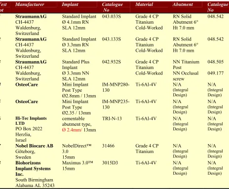
Eight commercially available implant designs (Table 1) were subjected to laboratory
analysis with a test set-up similar to that prescribed by ISO 14801(2003). Ten samples of
each of the eight designs were embedded vertically in acrylic blocks (Excel Heat Cure
Denture Acrylic, Wright Health Group Ltd, Dundee, Scotland) in a manner simulating 3mm
of crestal bone loss.
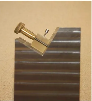
Each test implant supported a 5mm diameter cylindrical crown cast in Cobalt Chromium
alloy which seated onto the unmodified abutment. Test crowns extended apically onto
manufacturer’s pre-machined finishing lines where these existed. The height from the
occlusal surface of each test crown to the level of the embedding acrylic supporting the
implant was standardized at 14mm. The acrylic blocks carrying implant/abutment/crown
assemblies were subsequently loaded into a steel cradle (Fig 1) designed to securely
Testing was performed using a Lloyds LRX Tensometer (Lloyds Instruments Ltd, Hants,
UK - Fig 2). A schematic of the test set-up is shown in Fig 3. A small preload (0.5N) was
applied to each test sample to ensure that all components and acrylic blocks were fully
settled before each test was started.
Off-axis loading was applied to each implant assembly via the vertical piston of the
Tensometer, which descended at a continuous speed of 1mm/min until the piston achieved
a maximum travel of 6mm. This displacement parameter was set following initial piloting
of the Straumann implant designs and to ensure that data were recorded beyond the point of
yield under maximum load for each test sample. Although it transpired that for some
designs the test end-point did not conclude with a fractured implant (i.e. some tests ended
with a bent implant), this outcome did not form part of the current investigation.
Continuous output data of the applied load and distance traveled by the piston were
collected in real time with Nexygen software (Ametek, Paoli, USA). Data were
subsequently processed and analysed using Microsoft Excel 2000 and Epi Info™ software
(CDCP, Atlanta, Georgia, USA). Load/displacement curves characteristic for each implant
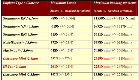
design were generated and mean maximum loads, maximum bending moments and their
appropriate standard deviations were calculated.
Results
Only 9 samples of the Straumann 3.3mm NN Implant, the NobelDirect™ 3.0 Implant, and
the Hi Tec TRI-N-13 Implant were tested as prescribed. This was due to faulty mounting in
the steel cradle, laboratory error during mounting and supply of an incorrect design due to
grouping of all test samples for individual implant designs, reinforcing the validity of the
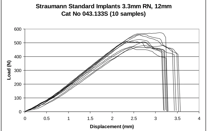
test set-up. Examples of curves for samples of two of the designs are shown in Figs 4 and 5.
Curves for all designs showed elastic deformation up to a point of failure which closely
approximated the maximum load value for the test sample. Shortly after achieving the
maximum load value, the load/ displacement curves of each test sample entered a failure
phase. For some implant designs, the curve of this failure phase concluded with a sharp
drop to a load value of zero indicating complete fracture of the test implant (Fig 4).
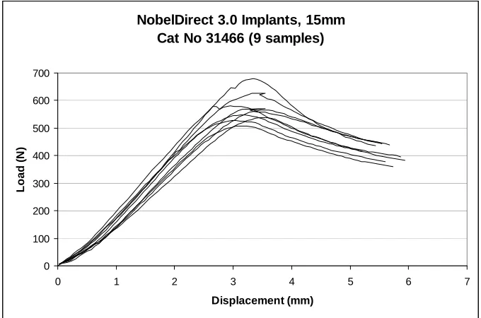
However, for other designs the test concluded before complete collapse of the test sample
when the piston reached 6mm of displacement, concluding with a bent implant still capable
of supporting a reduced load value (Fig 5). Since displacement of the samples under load
were also recorded, maximum bending moments could also be calculated for each implant
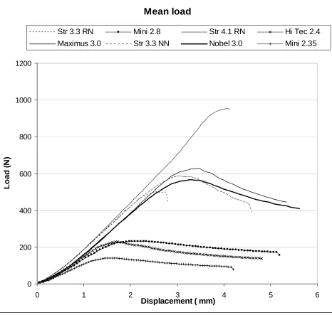
design. Test results for all implant designs are summarized in Table 2 and also in Figs 6
and 7.
For the purposes of statistical analysis, the non-parametric Wilcoxon test was applied to test
the differentials in the mean maximum load values for all pairs of implant designs.
Statistical analysis of the results indicated no significant difference between the
performance of the Straumann 3.3mm NN implant and the Maximus 3.0™ implant
(p=0.25), nor between that of the Osteocare 2.8mm Mini implant and the Hi Tec TRI-N-13
implant (p=0.14). For all other pairs of designs significant differences were found (p<0.02).
The two Straumann 3.3mm diameter designs produced significantly different outcomes for
implants with identical endosseous sections, but differing abutment connections (p=0.0008)
Discussion
The Straumann 4.1mm solid screw RN Implant is a well documented design which has
been in use since 1985 (Scacchi et al 2000) and does not appear prone to fracture (Buser et
al. 1997). Consistent with a previous report (Cehreli et al. 2004), no incidences of fracture
of this particular design appear to have been reported in the literature. The values attained
in the current study for this design may therefore be taken to represent a load resistance
representing complete safety in clinical practice.
The Straumann 3.3mm RN implant (which has the same abutment connection and platform
as the Straumann 4.1mm implant but a reduced endosseous diameter) has also been in use
for over 20 years (Scacchi et al 2000). However, only 2 studies were identified in the
literature from which limited data could be obtained for this design. A 10-year prospective
study of 298 consecutively placed Straumann 3.3mm RN implant concluded that this
implant had the potential to perform successfully over significant periods when clinical
protocols were carefully followed (Zinsli et al. 2004). However, only 67 implants were
used to support fixed restorations and of these 2 fractures (3%) were reported. Romeo et al
(2004) also experienced 2/22 fractures (9%) with this design but no fractures of 105 3.3mm
NN design implants (Romeo 2006b).
For all other implant designs tested in the study, clinical data does not appear to be
available. Therefore the laboratory results can only be evaluated subjectively against
clinical reports of the Straumann 4.1mm RN implant and the Straumann 3.3mm RN
Results obtained with the Straumann Ø3.3mm NN and the Straumann 3.3mm RN implant
assemblies indicate that the design of the abutment connection and the associated assembly
can influence the ability of the structure to withstand load (these implants feature identical
external endosseous sections and are manufactured in the same material). It seems likely
that the integral abutment design was a factor that contributed to the fact that both the
Maximus 3.0™ Implant and the NobelDirect™ 3.0 Implant out-performed the wider
Straumann Ø3.3mm RN implant. However, the fact that implants were manufactured in
different materials must also be considered (see Table 1). Titanium alloy (Ti-6Al-4V)
demonstrates better tensile properties than Grade 4 CP titanium, which in turn out-performs
lower grades of CP titanium (Williams 1977; Misch 1999; IMI Titanium 2005).
Although test outcomes for the Straumann Ø3.3mm NN, the Maximus 3.0™ and the
NobelDirect™ 3.0 suggest the possibility of increased fracture resistance for these designs
in comparison to the Straumann Ø3.3mm RN implant, the results for all these designs fell
significantly short of the values attained by the Straumann 4.1mm RN Implant. At present,
the lack of clinical and other data means that it is not possible to estimate the effect on
clinical performance.
Data obtained for the implant samples with diameters below 3mm showed maximum load
values well below that attained by the Straumann Ø3.3mm RN implant. These differences
were statistically significant. The authors believe the scale of these differences strongly
suggest that the risk of fracture for these designs could be clinically significant.
With regard to the clinical environment, it is important to remember that higher load values
al. 2000). Functional loads of approximately 100N have been noted for incisors, increasing
monotonically along the arch to a value approaching 300N in the molar region (Ferrario et
al. 2004). However, values of 300N have been suggested as an appropriate load value for
single premolar implants (Eskitascioglu et al. 2004) and maximum bite forces as high as
700N have been suggested in the second molar region of the natural dentition (van Eijden
1991). These values are certainly within range of 50% of the maximum load values of
many of the test samples used in the current study suggesting a risk of fatigue fracture for
some of these implants if used inappropriately.
Some attempt was made to standardize the length of implants involved in the investigation
at around 14mm. However, there was some variation with lengths of implant designs
varying from 12-15mm (Table 1). Whilst the current study has focused on the diameter of
commercially available implant designs, Petrie et al recently highlighted the fact that
length, diameter and taper are inter-related (Petrie & Williams. 2005). The possibility of
varying outcomes with different length implants must therefore be considered, particularly
for implants with a tapered design.
Conclusion
This study showed that implants with diameters below 3mm yielded results which were
significantly below those of a larger diameter. Given the lack of clinical data for
mini-implants, this suggests that caution advised when considering these implants for single
tooth and/or FPD restorations may be justified.
Acknowledgements: The authors gratefully thank Mr. Peter Gedling of Co. Durham and
References
Adell R, Leckholm U, Rockler B & Branemark P-I. (1981) A 15-year study of
osseointegrated implants in the treatment of the edentulous jaw. International Journal of
Oral Surgery 10: 387-416
Balkin BE, Steflik DE & Naval F. (2001) Mini-dental implant insertion with the
Auto-Advance technique for ongoing applications Journal of Oral Implantology 27: 32-37
Barber HD & Seckinger R. (1994) The role of the small diameter implant: A preliminary
report on the Miniplant system. Compendium 15: 1390-1392
Berglundh T, Persson L & Klinge B. (2002) A systematic review of the incidence of
biological and technical complications in implant dentistry reported in prospective
longitudinal studies of at least 5 years Journal of Clinical Periodontology 29 (supp 3):
197-212
Bragger U. (1999) Technical failures and complications related to prosthetic components of
implant systems and different superstructures Proceedings of the 3rd European Workshop
on Periodontology: Implant Dentistry p304-332. Quintessence, Berlin.
Brunski J, Puleo DA & Nanci A. (2000) Biomaterials and Biomechanics of Oral and
Maxillofacial implants: Current status and future developments International Journal of
Buser D, Merickse-Stern R, Bernard JP, Behneke A, Beheke N, Hirt HP, Belser UC &
Lang N. (1997) Long-term evaluation of non-submerged ITI implants. Part 1: 8-year life
table analysis of a prospective multi-centre study with 2359 implants Clinical Oral
Implants Research 8: 161-72
Cehreli MC, Akca K & Iplikcioglu H. (2004) Force transmission of one- and two- piece
morse taper oral implants: non-linear finite element analysis Clinical Oral Implants
Research 15: 481-489
Davarpanah M, Martinez H, Tecucianu JF, Celletti R & Lazzara R. (2000). Small-diameter
implants: indications and contraindications. Journal of Esthetic Dentistry 12: 186-194.
Eckert SE, Meraw SJ, Cal E & Ow RK. (2000) Analysis of incidence and associated factors
with fractured implants: A retrospective study International Journal of Oral and
Maxillofacial Implants 15: 662-667
Eskitascioglu G, Usumez A, Sevimay M, Soykan E & Unsal E. (2004) The influence of
occlusal loading location on stress transferred to implant-supported prostheses and
supporting bone: A three-dimensional finite element study Journal of Prosthetic Dentistry
91: 144-50
Ferrario VF, Sforza C, Serrao G, Dellavia C & Tartaglia GM. (2004) Single tooth bite
forces in healthy young adults Journal of Oral Rehabilitation 31: 18-22
Huang H-M, Tsai C-M, Chang C-C, Lin C-T & Lee S-Y. (2005) Evaluation of loading
conditions on fatigue-failed Implants by fracture surface analysis International Journal of
Oral and Maxillofacial Implants 20: 854-859
IMI Titanium Ltd. (2005) Engineering alloys pp 15-25. Birmingham, UK.
ISO 14801 (2003) Fatigue test for endosseous dental implants. International Organization
for Standardization, Geneva.
Krennmair G, Weinlander M. & Schidinger S. (2003) Provisional implants for anchoring
removable interim prostheses in edentulous jaws: A clinical study International Journal of
Oral and Maxillofacial Surgery 18: 582-588
Lemons JE & Dietsh-Misch F (1999) Biomaterials for Dental Implants Pp271-302.
Contemporary Implant Dentistry. Mosby, Missouri.
Leshem D, Mazor Z, Leshem R & Rosen D. (2003) A simple technique for fabrication of
immediate interim removable prosthesis supported by transitional implants Implant
Dentistry 12: 227-229
Misch CE & Bidez MW (1999) A scientific rationale for dental implant design pp329-346
Morgan MJ, James DF & Pilliar RM. (1993) Fractures of the fixture component of an
osseointegrated implant International Journal of Oral and Maxillofacial Implants 8:
409-414
Petrie CS & Williams JL. (2005) Comparative evaluation of implant designs: influence of
diameter, length, and taper on strains in the alveolar crest Clinical Implant Dentistry and
Related Research 16: 486-494
Plenk H & Zitter H. (1996) Endosseous Implants: Scientific and Clinical Aspects
Quintessence, Chicago.
Polizzi G, Fabbro S, Furri M, Hermann I & Squarzoni S. (1999) Clinical application of
narrow Branemark System implants for single-tooth restorations International Journal of
Oral and Maxillofacial Implants 14: 496-503
Rangert B, Krogh PH, Langer B & van Roekel N. (1995) Bending overload and implant
fracture: A retrospective clinical analysis International Journal of Oral and Maxillofacial
Implants 10: 326-334
Renouard F & Rangert B. (1999) Risk Factors in Implant Dentistry Quintessence Illinois
Romeo E, Lops D, Margutti E, Ghisolfi M, Chiapasco M & Vogel G. (2004) Long-term
survival and success of Oral Implants in the treatment of full and partial arches: A 7-year
prospective study with the ITI Dental Implant System International Journal of Oral and
Romeo E, Lops D, Amorfini L, Chiapasco M, Ghisolfi M. & Vogel G. (2006a) Clinical and
radiographic evaluation of small-diameter (3.3mm) implants followed for 1-7 years: a
longitudinal study Clinical Oral Implants Research 17: 139-148
Romeo E. (2006b) Personal communication (SRA).
Scacchi N, Merz BR & Schar AR. (2000) The development of the ITI Dental Implant
System Clinical Oral Implants Research 11(Supplement 1): 22-32
van Eijden TMGJ. (1991) Three-dimensional analyses of human bite-force magnitude and
moment Archives of Oral Biology 36: 535-539
Vigolo P. & Givani A. (2000) A clinical evaluation of single-tooth mini-implant
restorations: A five-year retrospective study Journal of Prosthetic Dentistry 84: 186-194
Vigolo P, Givani A, Majzoub Z & Cordioli G. (2004) Clinical evaluation of small-diameter
implants in single-tooth and multiple-implant restorations: A 7-year retrospective study
International Journal of Oral and Maxillofacial Implants 19: 703-709
Von Recuum A (Ed). (1986) Handbook of Biomaterials Evaluation. MacMillan, New
York.
Williams DF. (1977) Titanium as a metal for implantation. Part 1: Physical properties
Wiskott HWA, Nicholls JI, Belser UC. (1995) Stress fatigue: Basic principles and
Prosthetic Implications International Journal of Prosthodontics 8; 105-116
Zinsli B, Sagesser T, Mericske E & Mericske-Sterne R. (2004) Clinical evaluation of
small-diameter ITI implants: A prospective study International Journal of Oral and Maxillofacial
Implants 19: 1 92-99
Zubery Y, Nitzan B, Moses O & Tal H. (1999) Immediate loading of Modual Transitional
Implants: A histologic and Histomorphometric study in dogs International Journal of
Fig1: Each implant/crown assembly was mounted in an acrylic block which was itself secured in the cradle of the steel mounting block. This set-up held each implant with axis off-set 30° from the vertical (as per IS0 14801; 2003).
Fig 3: Schematic of test set-up.
L = Load applied via the tensometer ram.
A = Vertical height of tensometer ram. During the test, this distance reduces by a value D, the vertical displacement of the tensometer ram.
B = Horizontal offset of the tensometer ram. This value increases as the test proceeds. M = point at which bending moments are applied to the implant.
Straumann Standard Implants 3.3mm RN, 12mm Cat No 043.133S (10 samples)
0 100 200 300 400 500 600
0 0.5 1 1.5 2 2.5 3 3.5 4
Displacement (mm)
Load (
N
)
[image:19.612.115.458.434.652.2]NobelDirect 3.0 Implants, 15mm Cat No 31466 (9 samples)
0 100 200 300 400 500 600 700
0 1 2 3 4 5 6
Displacement (mm)
Lo
a
d (
N
)
[image:20.612.115.455.87.312.2]7
Mean load
0 200 400 600 800 1000 1200
0 1 2 3 4 5 6
Displacement ( mm)
Lo
a
d (
N
)
Str 3.3 RN Mini 2.8 Str 4.1 RN Hi Tec 2.4
[image:21.612.119.585.66.509.2]Maximus 3.0 Str 3.3 NN Nobel 3.0 Mini 2.35
Figure 6: Maximum load by diameter
0 200 400 600 800 1000 1200
2 2.5 3 3.5 4 4
Diameter (mm)
M
a
x
imu
m l
o
a
d
(
N
.5
)
Nobel 3.0
Straumann 3.3 NN
Mini 2.35
Maximus 3.0
Mini 2.8
Straumann 4.1
Straumann 3.3 RN
Hi Tec 2.4
Test lot
Manufacturer Implant Catalogue
No
Material Abutment Catalogue No 1 StraumannAG
CH-4437 Waldenburg, Switzerland
Standard Implant Ø 4.1mm RN SLA 12mm
043.033S Grade 4 CP Titanium Cold-Worked
RN Solid Abutment 6° Ht 7.0 mm
048.542
2 StraumannAG CH-4437 Waldenburg, Switzerland
Standard Implant Ø 3.3mm RN SLA 12mm
043.133S Grade 4 CP Titanium Cold-Worked
RN Solid Abutment 6° Ht 7.0 mm
048.542
3 StraumannAG CH-4437 Waldenburg, Switzerland
Standard Plus Implant Ø 3.3mm NN SLA 12mm
042.932S Grade 4 CP Titanium Cold-Worked NN Titanium Post NN Occlusal screw 048.505 049.177
4 OsteoCare Mini Implant Post Type Ø2.8mm / 13mm
IM-MNP280-130 Ti-6Al-4V N/A (Integral Design)
N/A
(Integral Design)
5 OsteoCare Mini Implant Post Type Ø2.35 / 13mm
IM-MNP235-130 Ti-6Al-4V N/A (Integral Design)
N/A
(Integral Design)
6 Hi-Tec Implants
LTD
PO Box 2022 Herzlia, Israel
cementable abutment type, Ø 2.4mm/ 13mm
TRI-N-13 Ti-6Al-4V N/A
(Integral Design)
N/A
(Integral Design)
7 Nobel Biocare AB Göteborg,
Sweden
NobelDirect™ 3.0
15mm
31466 Grade 4 CP Titanium N/A (Integral Design) N/A (Integral Design)
8 Biohorizons Implant Systems Inc.
South Birmingham Alabama AL 35243
Maximus 3.0™
15mm 3015D3 Ti-6Al-4V N/A (Integral Design)
N/A
[image:23.612.117.581.54.437.2](Integral Design)
Table 1: Implants and components used in the current study. Where implants did not
feature an integral abutment, standard cementable abutments were used (as listed) and
Implant Type / diameter Maximum Loads
Means (+/- standard deviations)
Maximum bending moments
Means (+/- standard deviations)
Straumann RN / 4.1mm 989N (+/- 107N) 11558Nmm (+/- 1251Nmm)
Straumann NN / 3.3mm 619N (+/- 50N) 6992Nmm (+/- 1317Nmm)
Straumann RN/ 3.3mm 515N (+/- 39N) 5311Nmm (+/- 455Nmm)
NobelDirect™ / 3.0mm 572N (+/- 53N) 5598Nmm (+/- 623Nmm)
Maximus ™/ 3.0mm 648N (+/- 45N) 7050Nmm (+/- 560Nmm)
Osteocare Mini /2.8mm 237N (+/- 37N ) 2319Nmm (+/- 411Nmm )
Hi Tec / 2.4mm 261N (+/- 31N) 2251Nmm (+/- 297Nmm)
[image:24.612.102.565.63.330.2]Osteocare Mini /2.35mm 147N (+/- 25N ) 1350Nmm (+/- 224Nmm)
Table 2: Maximum loads sustained and the maximum bending moments recorded for each