Int. J. Electrochem. Sci., 12 (2017) 5320 – 5330, doi: 10.20964/2017.06.08
International Journal of
ELECTROCHEMICAL
SCIENCE
www.electrochemsci.org
Electrochemical Performance of Li
2FeSiO
4as Anode Material
for Lithium-ion Batteries
Er-Qian Liang1,3, Li-Jun Song1,3, Shuang-Shuang Liu1,3, Yuan Guo2,3, Bao-Jun Yu2,3, Cheng-Yang Wang2,3, Ming-Wei Li1,3,*
1
Department of Chemistry, Tianjin University, Tianjin 300072, China 2
Key Laboratory for Green Chemical Technology of Ministry of Education, School of Chemical Engineering and Technology, Tianjin University, Tianjin 300072, China
3
Collaborative Innovation Center of Chemical Science and Engineering (Tianjin), Tianjin University, Tianjin 300072, China
*
E-mail: [email protected]
Received: 1 March 2017 / Accepted: 29 March 2017 / Published: 12 May 2017
The conventional cathode material Li2FeSiO4 (lithium iron orthosilicate) crystallites are synthesized by a solid state reaction, and used as the anode material for lithium-ion batteries. During the initial discharge, Li2FeSiO4 irreversibly decomposes and transforms. Although the resulted anodes hardly contain Li2FeSiO4 crystal phase, they show nice capacities and well cycling stability. At a current density of 50 mA g−1, the anode exhibits an initial discharge/charge of 799/569 mAh g−1, and keeps a discharge/charge capacity of 550/542 mAh g−1 after 60 cycles with 95.3% charge capacity retention. At a current of 1000 mA g−1, the anode shows a charge capacity of 191 mAh g−1 with 99.5% coulombic efficiency during the 300th cycle. The anode material after 300 cycles presents many microcrystal structures. It is proposed that the Li2FeSiO4 anodes transfer energy via a reversible conversion reaction.
Keywords: Lithium iron orthosilicate; anode material; lithium-ion battery; cycling stability
1. INTRODUCTION
Compared with graphite, some Li-containing alloy anode materials have rather high theoretical capacities [4], such as 410 mAh g−1 for LiZn, 993 mAh g−1 for LiAl, and even 3579 mAh g−1 for Li15Si4. But high-capacity Li-alloy anodes often suffer from the drastic volume variation and capacity fading during cycling. For example, crystalline Si is pulverized into amorphous Si after a single discharge/charge cycle due to a 280% volume expansion after full lithiation [5].
Apart from the lithium insertion/extraction and alloying mechanisms, some other anode materials act the lithiation/delithiation mechanisms in the reversible conversion reactions, where the transition metal comprising compounds (MXy, M=Co, Ni, Cu, Fe, etc; X=P, S, O, F, Cl, etc.) are
electrochemically reduced into metal (M0) nanoparticles. As being charged, the metal nanoparticles are converted into their original states (MXy) [2, 6–8]. Theoretically, MXy compound anodes often have
high capacities. For example, the CoO anode has a theoretical capacity of 715 mAh g−1 caused by a reversible reaction mechanism as follows.
CoO + 2Li+ + 2e–↔ Co + Li2O (1)
Additionally, the Co3O4 anode has a higher theoretical capacity (890 mAh g−1) as metal ions are completely reduced [8].
Co3O4 + 8Li+ + 8e
–↔ 3Co + 4Li
2O (2)
Compared with Li-alloys, the reversible reaction mechanism of MXy anode may induce the
smaller volume variation during cycling. Nevertheless, it still is not enough for keeping the cycling stability of binary oxides. It was reported that the capacity of FeO anode fades from 730 to 300 mAh g−1 after 50 cycles at a discharge/charge rate of 0.2 C [6].
Except for the traditional anode materials such as graphite, silicon or other Li-alloys, and binary oxides [2–11], some polyanionic compounds, such as LiFePO4, Li2MnSiO4, and Li2FeSiO4, are studied to be used as the anode material and exhibit unexpectedly high capacities and cycling stability [12–16] Among them, the Li2FeSiO4 shows prominent anode performance [14]. The reported LiFeSiO4 anode delivers an initial discharge/charge capacity of 880/618 mA g−1 at a current density of 50 mA g−1, and a discharge capacity of ~449 mAh g−1 at 100 mA g−1 after 173 cycles. The capacities are much higher than that of Li2FeSiO4 as cathodes [15–22]. Due to its low-cost raw materials, multivalence of Fe, and complicated polyanionic crystal structure, the anode performance of Li2FeSiO4 needs further investigation.
It is found that the Li2FeSiO4 crystallites as anode material irreversibly decompose during the initial discharge. Though the resulted anodes hardly contain Li2FeSiO4 crystal phase, they shows nice capability and well stability during cycling. The Li2FeSiO4-derived anode material contains many microcrystal structures after 300 cycles. Their lithiation/delithiation mechanism is discussed.
2. EXPERIMENTAL
2.1. Synthesis of Li2FeSiO4 crystallites
The precursor of Li2FeSiO4 was prepared by a modified sol–gel process [16]. The main raw materials include CH3COOLi·2H2O, Fe(NO3)3·9H2O, and SiO2 fine powder (CAB-O-SIL M5). First, citric acid, ethylene glycol, and SiO2 in a molar ratio 1/3/3 were orderly dissolved and dispersed into deionized water to form a SiO2 suspension under stirring. Then, two aqueous solutions of CH3COOLi·2H2O and Fe(NO3)3·9H2O were respectively added into the suspension. After the mixture having been stirred at 80 oC for 12 h, ACM (20% of the theoretical mass of Li2FeSiO4) was added. The new mixture was stirred at 80 oC until a gel formed. The gel was dried, ground, and then heated at 700 o
C in N2 flow for 10 h to synthesize Li2FeSiO4 crystallites.
2.2. Characterization
The precursor of Li2FeSiO4 was analyzed by thermogravimetric analysis and differential scanning calorimetry (TG–DSC, STA 409 PC/PG, NETZSCH) from room temperature to 800 °C in N2 flow. The carbon content of the synthetic carbon-coated Li2FeSiO4 crystallites was measured by TG– DSC analysis in air flow. The pristine, discharged, and charged anodes were analyzed by a powder X-ray diffractometer (XRD, D/MAX-2500, Rigaku) using Cu Kα radiation (λ = 0.15406 nm). The anode materials′ morphology and microstructures were recorded by a field emission scanning electron microscope (SEM, Nanosem 430, FEI) and a high-resolution transmission electron microscope (HRTEM, Tecnai G2 F20, FEI). The cycled anode material was carefully scraped off the copper current collector, and analyzed by HRTEM and XRD.
2.3. Electrochemical measurements
electrochemical workstation (CHI604A, CH Instruments, China) at a scan rate of 0.1 mV s−1 between 3.0 and 0 V.
[image:4.596.183.412.282.454.2]3. RESULTS AND DISCUSSION
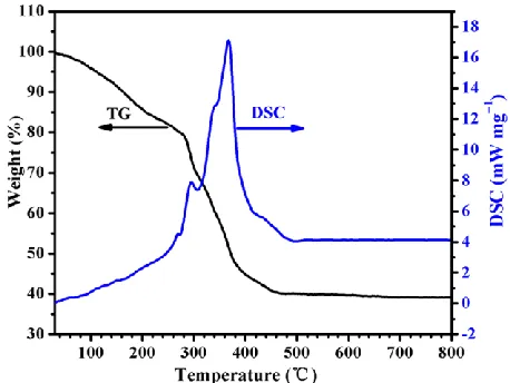
Fig. 1 displays the TG–DSC curves of the precursor (without ACM) of Li2FeSiO4. Below 460 °C, the total weight loss is about 60%. A sharp weight loss between 280 and 460 °C with two exothermic peaks at 295 and 367 °C corresponds to the decomposition of citric acid and the reactions among acetate, nitrate, and SiO2. Above 500 °C, there is no obvious weight loss and endothermic/exothermic peaks. It indicates that the Li2FeSiO4 crystallites already formed before 500 °C. The experimental results are similar with previous reports [17, 18]. Hence, the Li2FeSiO4 crystallites were synthesized at 700 °C in this work.
Figure 1. TG–DSC curves of the precursor of Li2FeSiO4.
Fig. 2 presents the XRD pattern of the synthetic carbon-coated Li2FeSiO4. Almost all diffraction peaks are indexed to a monoclinic Li2FeSiO4 structure (ICSD 246132, S.G. P21/n, a = 8.2407Å, b = 5.0132 Å, c = 8.2302 Å, and β = 99.03°), which is quite consistent with previous reports [14, 19–22]. The unit cell of Li2FeSiO4 is illustrated in Fig. 2. It consists of alternating layers being perpendicular to the b axes. In each layer, the atoms of Li, Fe, Si, and the O atoms between them are arranged in an uneven honeycomb lattice. Half of Li atoms respectively connect with three O atoms, and the rest Li atoms form LiO4 tetrahedra. The alternating layers are connected by MO (M=Li, Fe, or Si) bonds along the b axes of LiO4, FeO4, and SiO4 tetrahedra. The pattern of Li2FeSiO4 unit cell is helpful to image the after-mentioned products of Li2FeSiO4 decomposition.
The mean size of the synthetic Li2FeSiO4 crystallites is about 28 nm calculated by Scherrer formula. Although the carbon-coated Li2FeSiO4 has a carbon content 13.4 wt% which results from the carbonization of reducing agents, no distinct diffraction peaks for ordered carbon are detected. The residual carbon should be amorphous.
[image:5.596.187.406.139.296.2]
exhibits the well-ordered crystal planes with a lattice distance of 0.275 nm, corresponding to the diffraction peak (-301) or (-103) for Li2FeSiO4 shown in Fig. 2. The crystallite is coated with a thin layer (thickness <1.0 nm) of amorphous carbon.
[image:5.596.49.547.342.489.2]Figure 2. XRD pattern of the synthetic Li2FeSiO4. The insert is the unit cell of Li2FeSiO4.
Figure 3. SEM and HRTEM images of the synthetic Li2FeSiO4: (a) SEM image, (b) HRTEM image of the aggregated particles, and (c) HRTEM image of a magnified crystallite.
[image:5.596.185.411.542.727.2]
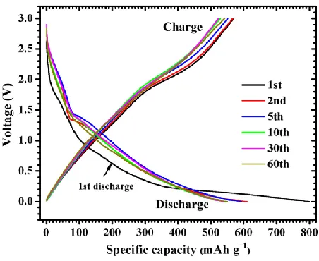
Fig. 4 exhibits the discharge/charge curves of the Li2FeSiO4-derived anode. It delivers an initial discharge/charge capacity of 799/569 mAh g−1 at a current density of 50 mA g−1. The initial capacity loss 230 mAh g−1 is mainly attributed to the lithium loss caused by the irreversible reduction of Li2FeSiO4 and the formation of solid electrolyte interface (SEI) layers. After the initial charge, the subsequent discharge/charge curves show similar profiles, implying the anode’s well reversibility. The charge plateaus at ~2.0 V and the discharge plateaus at ~1.4 V indicate redox reactions occurring.
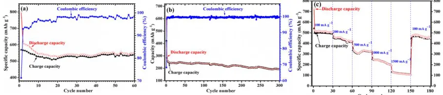
Figure 5. Electrochemical performance of Li2FeSiO4-derived anodes: (a) cycling performance at a low current density of 50 mA g−1, (b) cycling performance at a high current of 1000 mA g−1, (c) rate performance at current densities varied from 100 to 1500 mA g−1.
As shown in Fig. 5, the anode exhibits nice capabilities and cycling stability. At a low current density of 50 mA g−1 (Fig. 5a), it presents an initial charge capacity of 569 mAh g−1, and keeps a charge capacity of 542 mA h g−1 during the 60th cycle, corresponding to 95.3% charge capacity retention. At a high current density of 1000 mA g−1 (Fig. 5b), the anode keeps a charge capacity of 191 mAh g−1 with a coulombic efficiencies of 99.5% during the 300th cycle.
The Li2FeSiO4-derived anode shows a discharge/charge capacity of 550/542 mAh g−1 during the 60th cycle. Partial capacity should be attributed to the conductive carbons including Super P carbon black and coated carbon, which are hard carbons or non graphitable carbons. It was reported that the discharge/charge capacity of a Super P anode is 610/518 mAh g−1 [24]. Generally, hard carbons have anode capacities between 200 and 600 mAh g−1 [25]. According to the contents and capacities of conductive carbons, the capacity of the Li2FeSiO4-derived active material is around 520 mAh g−1.
The anode exhibits well rate capabilities and stability at a current density varied from 100 to 1500 mA g−1. As shown in Fig. 5c, the reversible capacities are 541, 456, 338, 253 and 132 mA h g−1 at the start cycle at current densities of 100, 200, 500, 1000 and 1500 mA g−1, respectively. After 150 cycles and the current density returned back to 100 mA g−1, the anode has a reversible capacity of 446 mAh g−1 with a coulombic efficiency of 99.1%.
To investigate the lithiation/delithiation mechanism of the Li2FeSiO4-derived anodes, the discharged and charged anodes were analyzed by XRD and HRTEM. CV spectra of the anode were also studied.
[image:6.596.71.525.191.289.2]
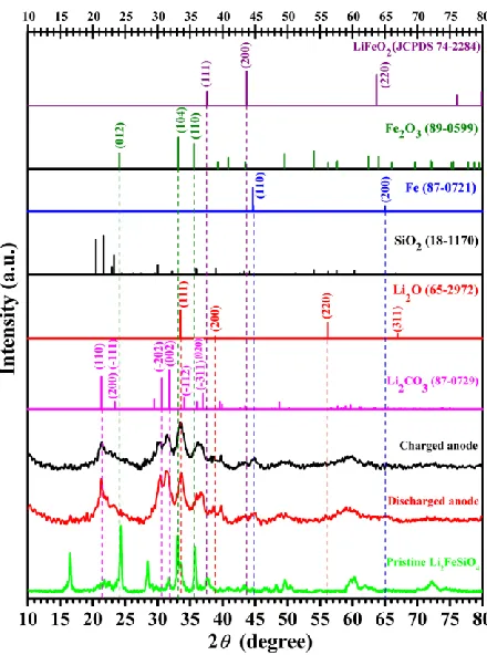
They both exhibit the predominated diffraction peaks for Li2CO3, which is an ever-present component of SEI layers as carbonate-based non-aqueous electrolyte is used [14]. The broad diffraction peaks near 21o and 60o are indexed to the amorphous SiO2 resulting from the decomposition of Li2FeSiO4 [26]. Two peaks (111) and (220) for Li2O mainly appear in the XRD spectrum of the discharged anode.
Figure 6. Ex-situ XRD patterns of Li2FeSiO4-derived anodes after the initial discharge/charge at a current density of 10 mA g−1. The standard XRD patterns of Li2CO3, Li2O, SiO2 (tridymite), Fe, α-Fe2O3 (hematite), and LiFeO3 are shown for comparison.
Metallic Fe and Fe-containing compounds play a key role for the anodes’ energy conversion. However, due to the broad and overlapped diffraction peaks caused by the nanosized and/or amorphous particles, it is difficult to identify the metallic Fe by XRD results. Similar situation had ever been reported during the investigation on CoO anodes [6]. There are no obvious diffraction peaks for metallic Co because the presumed nanosized metallic Co nanoparticles are smaller than the X-ray coherence length. The charged anode shows a more intense diffraction peak at 33o, which is attributed to a mixed peak consisting of (104) peak for α-Fe2O3 and (111) peak for Li2O. No obvious diffraction peaks for LiFeO2 are found. According to Fig.6, there possible is trace metallic Fe exists in both discharged and charged anodes.
[image:7.596.187.407.154.450.2]
microcrystal structures are indexed to Li2CO3, which more often has wider lattice spaces than α-Fe2O3. At the particle edge shown in Fig. 7a, a lattice space of 0.248 nm is indexed to the (020) diffraction peak for Li2CO3. In Fig. 7b, the lattice spaces 0.289 and 0.280 nm respectively result from the (-202) and (002) planes of Li2CO3. Noticeably, the lattice spaces of 0.268 and 0.249 nm shown in Fig. 7c are respectively attributed to the (104) and (110) planes of α-Fe2O3. The 0.231 nm lattice space possibly originates from the (200) planes of Li2O, which reflects residual Li2O in the charged anode. Many lattice spaces shown in Fig.7 are difficult to be indexed by certain crystal phases. It reflects the mixed microcrystal phases and their ongoing phase transits involving Li2CO3, Li2O, Fe, α-Fe2O3, etc. Nevertheless, the charged anode keeps ordered microcrystal structures after 300 cycles at a high current density of 1000 mA g−1. It also corresponds to the anode’s 99.5% coulombic efficiency shown in Fig. 5b.
Figure 7. HRTEM images for the powder scraped from the cycled anodes: (a) after the initial discharge at a current density of 10 mA g−1, (b) after the initial charge at 10 mA g−1 (the insert is a low magnified image), and (c) after the 300th charge at 1000 mA g−1.
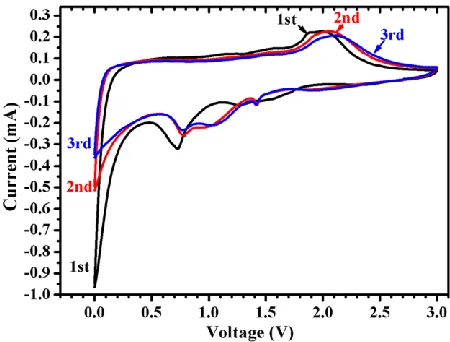
Figure 8. CV spectra of Li2FeSiO4-derived anode.
[image:8.596.69.526.283.436.2] [image:8.596.184.409.504.675.2]
the reduction of Fe2+→Fe0 along with Li2FeSiO4 decomposition [6, 27]. The sharp reduction peak at just above 0 V results from the formation of SEI layers, and the interfacial metallic lithium storage [14, 28, 29]. During the initial charge from 0 to 3 V, the peak at ~1.95 V corresponds to the oxidation of metallic Fe [30−34]. From the 2nd cycle, the new reduction peaks around 1.42 V are assigned to the reduction of Fe3+. The CV spectra are different with that of a Li2FeSiO4/activated carbon hybrid supercapacitor [35], and hence reveal that the Li2FeSiO4-derived anodes have no obvious capacitance behaviors. The oxidation/reduction peaks in CV curves reflect the redox reactions within the anodes during cycling.
As the above-mentioned results of XRD and HRTEM, Li2FeSiO4 crystallites prompt disappears after the initial discharge. The discharged anode contains Li2CO3, amorphous SiO2, Li2O, and possible metallic Fe. There is a reduction peak at 0.72 V (vs Li+/Li) in the CV spectra. So we propose that Li2FeSiO4 decomposed during the initial discharge as follows.
Li2FeSiO4 + 2Li+ + 2e– → 2Li2O + Fe + SiO2 (3)
Li2FeSiO4-derived anodes show high charge capacities (>500 mAh g−1) in literature [14] and this work. Their capacities likely correspond to the valence state change of iron between Fe0 and Fe3+. We propose the anodes transferring energy via a reversible conversion reaction being simplified as follows.
Fe + 3/2 Li2O ↔ 1/2 Fe2O3 + 3 Li+
+ 3 e– (4)
1/2 Li2O per Li2FeSiO4 remains due to its excess for reacting with Fe.
In this mechanism, Li2FeSiO4-derived anodes have a theoretical capacity of 497 mAh g–1, which is higher than the theoretical capacity of graphite.
The performance of α-Fe2O3 anode has widely been investigated [31−34], and can be used to compare with the results of Li2FeSiO4-derived in this work. Li2FeSiO4 anode material has an advantage over α-Fe2O3. It forms amorphous SiO2 during the initial discharge. Amorphous SiO2 may buffer the anode volume variation during cycling, and improve the anodes’ cycling stability. Additionally, the excess Li2O in reaction (3) possibly favor the formation of Fe3+ (i.e., Fe2O3), which benefits the high capacities of anodes. In literatures, more redox peaks appeared in the CV spectra of α-Fe2O3 anodes, and indicate various valence states of iron during charge/discharge process. Partial oxygen in α-Fe2O3 is robbed to form the SEI layers. It induces the decrease of anodes’ capacity due to the valence state change between Fe2+ and Fe0.
4. CONCLUSIONS
density of 50 mA g−1, the anode keeps a charge capacity of 542 mAh g−1 and 95.3% charge capacity retention during the 60th cycle. At 1000 mA g−1, the anode still presents a charge capacity of 191 mAh g−1 and 99.5% coulombic efficiency during the 300th cycle. It is proposed that the Li2FeSiO4-derived anodes transfer energy via a reversible reaction involving metallic Fe and Fe3+.
ACKNOWLEDGEMENTS
This research is financially supported by the National Nature Science Foundation of China (NSFC 5117260) and the Nature Science Foundation of Tianjin city (No. 14RCHZGX00859 and No. 14JCTPJC00484).
References
1. M. S. Whittingham, Chem. Rev., 104 (2004) 4271.
2. V. Aravindan, Y.-S. Lee and S. Madhavi, Adv. Energy Mater., 5 (2015) 1402225. 3. Z. Guo, C. Wang, M. Chen and M. Li, Int. J. Electrochem. Sci.,8 (2013) 2702. 4. M. N. Obrovac and V. L. Chevrier, Chem. Rev., 114 (2014) 11444.
5. M. N. Obrovac and L. J. Krause, J Electrochem. Soc., 154 (2007) A103.
6. P. Poizot, S. Laruelle, S. Grugeon, L. Dupont and J.-M. Tarascon, Nature, 407 (2000) 496. 7. J. Cabana, L. Monconduit, D. Larcher and M. R. Palacín, Adv. Mater., 22 (2010) E170. 8. F. Zhang, D. D. Qi and X. G. Zhang, Int. J. Electrochem. Sci., 11 (2016) 189.
9. W. J. Zhang, J. Power Sources, 196 (2011) 13.
10. X. Guo, C. Wang, M. Chen, J. Wang and J. Zheng, J. Power Sources, 214 (2012) 107. 11. Y. Wang, X. Wen, J. Chen and S. Wang, J. Power Sources, 281 (2015) 285.
12. N. Kalaiselvi, C. H. Doh, C. W. Park, S. I. Moon and M. S. Yun, Electrochem. Commun., 6 (2004) 1110.
13. V. Aravindan, K. Karthikeyan, S. Amaresh, H. S. Kim, D. R. Chang and Y. S. Lee, Ionics, 17 (2011) 3.
14. Y. Xu, Y. Li, S. Liu, H. Li and Y. Liu, J. Power Sources, 220 (2012) 103.
15. G. R. Liu, S. C. Zhang, X. Wei, S. B. Wang, and Y. Yu, Int. J. Electrochem. Sci., 1 (2016) 6799. 16. S. S. Liu, L. J. Song, B. J. Yu, C. Y. Wang and M. W. Li, Electrochim. Acta, 188 (2016) 145. 17. Y. Chen, D. Zeng, J. Peng, S. Hu, Z. Li and G. Lei, Funct. Mater. Lett., 6 (2013) 1.
18. P. Zuo, T. Wang, G. Cheng, C. Du, Y. Ma, X. Cheng and G. Yin, J. Solid State Electrochem., 17 (2013) 1955.
19. J. Yang, X. Kang, L. Hu, X. Gong, D. He, T. Peng and S. Mu, J. Alloys Comp., 572 (2013) 158. 20. Z. Chen, S. Qiu, Y. Cao, J. Qian, X. Ai, K. Xie, X. Hong and H. Yang, J. Mater. Chem. A, 1
(2013) 4988.
21. H. Zhu, X. Wu, L. Zan and Y. Zhang, Electrochim. Acta, 117 (2014) 34.
22. T. Masese, C. Tassel, Y. Orikasa, Y. Koyama, H. Arai, N. Hayashi, J. Kim, T. Mori, K. Yamamoto, Y. Kobayashi, H. Kageyama, Z. Ogumi and Y. Uchimoto, J. Phys. Chem. C, 119 (2015) 10206.
23. S. Y. Yan, C. Y. Wang, R. M. Gu, S. Sun and M. W. Li, J. Alloys Comp., 628 (2015) 471. 24. R. M. Gnanamuthu and C. W. Lee, Mater. Chem. Phys., 130 (2011) 831.
25. S. Goriparti, E. Miele, F. De Angelis, E. Di Fabrizio and R. P. Zaccaria, J. Power Sources, 257 (2014) 421.
26. J. R. Martínez, S. Palomares-Sánchez, G. Ortega-Zarzosa, F. Ruiz and Y. Chumakov, Mater. Lett., 60 (2006) 3526.
28. Y. Xiao, X. Wang, W. Wang, D. Zhao and M. Cao, ACS Appl. Mater. Interfaces, 6 (2014) 2051. 29. J. Jamnik and J. Maier, Phys. Chem. Chem. Phys.,5 (2003) 5215.
30. J. Morales, L. Sánchez, F. Martín, F. Berry and X. Ren, J. Electrochem. Soc., 152 (2005) A1748. 31. M. V. Reddy, T. Yu, C.-H. Sow, Z. X. Shen, C. T. Lim, G. V. Subba Rao and B. V. R. Chowdari,
Adv. Funct. Mater., 17 (2007) 2792.
32. Y. Zhao, J. Li, Y. Ding and L. Guan, Chem. Commun., 47 (2011) 7416.
33. M. Wu, J. Chen, C. Wang, F. Wang, B. Yi, W. Su, Z. Wei and S. Liu, Electrochim. Acta, 132 (2014) 533.
34. T. R. Penki, S. Shivakumara, M. Minakshi and N. Munichandraiah, Electrochim. Acta, 167 (2015) 330.
35. K. Karthikeyan, V. Aravindan, S. B. Lee, I. C. Jang, H. H. Lim, G. J. Park, M. Yoshio and Y. S. Lee, J. Alloys Comp., 504 (2010) 224.