International Journal of Innovative Technology and Exploring Engineering (IJITEE) ISSN: 2278-3075, Volume-8 Issue-7, May, 2019
Comparision of Seismic Analysis of a Residential
Structure between Normal Rcc, Shear Wall
Columns
T.G.N.C.Vamsi Krishna, S.V.Surendhar,Mirza Mahaboob Baig,Atif Zakaria
Abstract: In high raised structures, mostly columns are preferred with either Normal RCC Columns or Steel Columns. In India, most probably RCC columns only used because it depends on the availability of materials, workmanship and RCC Columns occupies more space in high raised structures due to the large dimensions but it controls the large deflections of the structure due to an earthquake. Steel Columns occupied less space and it can also give more strength than RCC Columns but the availability of material is less because steel consumption in India very low compared with other foreign countries and due to the earthquake large deformations occurred in steel columns. For controlling or eliminating these problems shear wall columns are better in High Raised Structures. Shear wall columns stronger than the RCC Columns, it can increase usable floor area in the structure and also it can decrease the deflections than the RCC Columns. Considered a geometrical irregularity of residential structure (G+18 Storey) in the seismic zone-III, Medium type of soil condition. Analyse the structure with Linear and Non-linear Dynamic analysis in various types of columns they are Normal RCC, Shear wall Columns by ETAB Software. Due to an analysis of these structures compare the Storey displacements, Storey drifts, Base shears, Response Spectrum curve, Time History curve, Self-weight, Time period of the structure. From these above parameters conclude that shear wall type of columns most suitable in all possible conditions.
KEYWORDS: RCC Columns, Shear Wall Columns, Deflections, Self-weight, Time period of the structure.
I. INTRODUCTION
In general, especially in India high raised structures constructed with either reinforced concrete columns or steel columns. In India, the production of steel is very low compared with other countries. Due to the RCC columns in high raised structures, the column sizes are increased more, a large amount of steel quantity required and also it occupies the more feasibility space in the rooms.
Revised Manuscript Received on May 06, 2019
T.G.N.C.Vamsi Krishna, UG (Civil Engineering) from JNTUK and pursuing Post Graduation (Structural Engineering) in VFSTR University, Vadlamudi, Guntur, Andhra Pradesh,
S V Surendhar, Asst. Professor in VFSTR University, Vadlamudi, Guntur, Andhra Pradesh,
Mirza Mahaboob Baig, UG (Civil Engineering) from JNTUK and pursuing Post Graduation (Structural Engineering) in VFSTR University, Vadlamudi, Guntur, Andhra Pradesh,
Atif Zakaria, UG (Civil Engineering) from OIU (Khartoum, Sudan) and pursuing Post Graduation (Structural Engineering) in VFSTR University, Vadlamudi, Guntur, Andhra Pradesh,
They conclude that opening type of shear walls is more economical but resistance behaviour from an earthquake is low. HimaleeRahangdale, S.R.Satone., Studied G+5 storey building at Seismic zone IV using STAAD Pro software. In this they changing various positions of shear wall in structure and analysed. Finally, they concluded that shear walls at corner sides of the structure behaving the full load resisting from an earthquake and some other positions of shear walls also behaving similar but the columns axial forces and bending moments are raised very high but the shear wall can be supported that forces and moments also.
II. OBJECTIVE
Considering the G+18 storey of a geometrical irregularity of residential high raised structure with variation of both longitudinal and transverse direction using 2 models (RCC Columns and Shear wall Columns) by ETAB software under Seismic Zone-III at Medium soil condition. The linear static, dynamic analysis and Nonlinear Dynamic analysis of the structure. Comparing these two models with the help of following parameters such as Storey displacements, Storey drifts, and Storey shear, Stiffness of column, Self-weight, Time period of the structure, Response spectrum and Time history curve.
III.REINFORCED CONCRETE SHEAR WALL
Mostly in residential buildings, Reinforced Concrete shear wall are used. In this, reinforcement should be provided in both longitudinal and transverse directions and also bars are anchored and closely spaced at the end of each wall.RC Shear wall of thickness varied from 120mm to 500mm depending upon many factors like Number of storeys in the structure, Age of the Structure, Thermal Insulation required in a structure.
[image:2.595.321.531.51.133.2]It is connected from foundation to the top of the structure but sometimes due to the doors, windows shear wall openings are required and also at parking places especially in tall structures. Shear wall efficiency totally depends on Stiffness, Rigidity of the structure. Shear walls are provided with either solid Shear wall, Opening type shear wall. The opening type of shear walls are varied with various cross sections it’s depending on their situation as shown in Fig 1. The shape, position of shear wall is impact on behaviour of shear wall. Mostly shape of shear wall either plane or flanged or channel section as shown in Fig 2.
[image:2.595.61.269.633.765.2]Fig. 1 Various opening ways of shear walls
Fig. 2 Various Shapes of Shear walls
IV. MODELLING & ANALYSIS
A. Description of the model
In this study, residential building is considered. The structure has geometric irregularities such as varying spacing between columns in X & Y directions. The AutoCAD plan of the structure is shown in Fig. 3. The same building plan is used to model and design an RCC Column structure and a Shear wall Column structure. The floor to floor height, dead loads, live loads and seismic analysis data remains same for both the structures. The structure consists of G+18 storeys. The Equivalent static analysis, Response spectrum analysis and Non-linear time history analysis are performed using ETAB software.
B. Details of the structure
International Journal of Innovative Technology and Exploring Engineering (IJITEE) ISSN: 2278-3075, Volume-8 Issue-7, May, 2019
Fig. 3 AutoCAD Plan of the Structure.
Fig. 4 RCC Column of the Structure
Fig. 5 Shear wall Column of the Structure.
V. RESULTS & DISCUSSIONS:
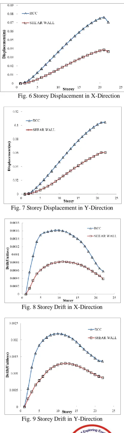
1. RCC Column structure has more storey displacement than the Shear wall Column structure in both the directions as shown in Fig. 6 & 7.
2. Shear wall Column structure has less storey drift than the RCC Column Structure in both the directions as shown in Fig. 8 & 9.
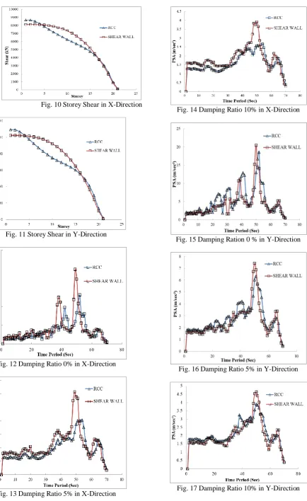
3. In both X, Y Directions, storey shears in RCC Columns has more shear than the Shear wall Columns up to 4th storey, from 5th storey to 16th storey Shear wall Columns has more storey shears than the RCC Columns and the remaining storeys; Shear wall Columns has less shear than the RCC Columns as shown in Fig. 10 & Fig. 11.
Fig. 6 Storey Displacement in X-Direction
[image:3.595.68.271.49.221.2]Fig. 7 Storey Displacement in Y-Direction
Fig. 8 Storey Drift in X-Direction
[image:3.595.325.550.381.832.2]Fig. 10 Storey Shear in X-Direction
Fig. 11 Storey Shear in Y-Direction
Fig. 12 Damping Ratio 0% in X-Direction
[image:4.595.331.523.49.197.2]Fig. 13 Damping Ratio 5% in X-Direction
Fig. 14 Damping Ratio 10% in X-Direction
Fig. 15 Damping Ration 0 % in Y-Direction
[image:4.595.68.270.149.732.2]Fig. 16 Damping Ratio 5% in Y-Direction
[image:4.595.326.524.391.731.2]International Journal of Innovative Technology and Exploring Engineering (IJITEE) ISSN: 2278-3075, Volume-8 Issue-7, May, 2019
[image:5.595.319.537.59.389.2]Fig. 18 Time History Curve in X-Direction
Fig. 19 Time History Curve in Y-Direction
Fig. 20 Time Period of the Structure
Fig. 21 Self-weight of the Structure
Fig. 22 Base Shear in X-Direction
[image:5.595.318.538.86.667.2]Fig. 23 Base Shear in Y-Direction
Fig. 24 Maximum Storey Stiffness in X-Direction
Fig. 25 Maximum Storey Stiffness in Y-Direction
[image:5.595.62.279.285.771.2] [image:5.595.315.549.393.835.2]4. From Fig. 12 to 17 observed that response spectrum curve at damping ratios of 0%, 5%, 10% in both directions are slight variations in both RCC Column and Shear Wall Column Structure.
5. Time History Curve indicates that Shear wall Column structure is slightly more than the RCC Column Structure as shown in Fig. 18 & 19.
6. The time period is more in RCC Column structure than the Shear wall Column structure as shown in Fig. 20. 7. The self-weight of the structure in the RCC Column
structure is more than the Shear wall Column Structure as shown in Fig. 21.
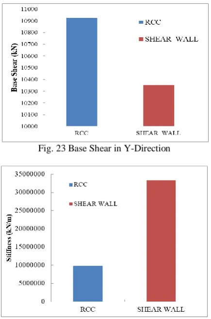
8. The base shears of the structure in both X & Y Directions are less in shear wall Column structure than the RCC Column structure as shown in Fig. 22 & 23. 9. Stiffness of the structure in Shear wall columns is more
than the RCC Column Structure in both the directions as shown in Fig. 24 & 25.
10.From Fig. 26, the storey forces in RCC Structure are slightly higher than the Shear wall Column Structure.
VI. CONCLUSIONS
1. The Storey displacement in Shear wall column structure is less than the RCC Column structure because the presence of a shear wall in the structure can help to control the displacements in the structure. Due to this, structure performance increases more.
2. The Storey drift in RCC Column structure is more than the Shear wall Column structure because the storey drifts always depending on the storey displacement of the structure. So, the shear wall column structure is most preferable than the RCC Column structure.
3. The storey shears in both structures at both directions slightly varied at particular storeys. It cannot affect the structure.
4. Response spectrum curve indicates that shear wall structure has high acceleration than the RCC structure. Here, acceleration more in structure indicates the resistance capacity of the structure from the earthquakes so; shear wall structure is stronger than RCC structure. 5. The time history curve says that both structures can be
performed similarly in both directions.
6. The Time period of shear wall structure indicates the stability condition of the structure.
7. The Self-weight of the shear wall structure is less than the RCC Column structure. Due to less self-weight of the structure base shear also decreases in both directions. So, the shear wall structure is stronger than the RCC structure.
8. The stiffness of the structure more means it can stand to control or resist the earthquake forces in the structure. Here, the shear wall structure has more stiffness than the RCC structure.
9. Finally, the shear wall type of column structures can give more space, high strength and cost of construction also will decrease when compared to the Normal Columns in RCC structure.
REFERENCES
1. Swetha K.S and Akhil P.A,“Effect of Openings in Shear
Wall,”International Research Journal of Engineering and
Technology,vol. 04, issue 5, pp. 1601-06, 2017.
2. Ashok Kankuntla, PrakarshSangave and ReshmaChavan, “Effects of
Openings in Shear Wall,” IOSR Journal of Mechanical and Civil
Engineering, vol. 13, issue 1 Ver. II, pp.01-06, 2016.
3. HimaleeRahangdale and S.R.Satone,“Design and Analysis of
Multi-storeyed Building with Effect of Shear Wall,” International Journal of
Engineering Research and Applications, vol. 3, issue 3, pp.223-232, 2013.
4. M. Hosseini, M. Farookh, and H. Hosseini, “Seismic Analysis of High
Rise Building with L Shape Shear Walls at the Centre Core and
Corners with Opening,” International Journal of Engineering Trends
and Technology, vol. 49, no. 5, pp. 317–329, 2017.
5. P. S. Kumbhare, A. C. Saoji,“Effectiveness of Changing Reinforced
Concrete Shear Wall Location on Multi-storeyed Building,”
International Journal of Engineering Research and Applications,vol. 2, issue 5, pp.1072-1076, 2012.
6. “Fig 6: Shear Walls – Solid, with Openings, Coupled,” The
Constructor, 04-Sep-2018. [Online]. Available:
https://theconstructor.org/structural-engg/shear-wall-types-efficiency/6820/.
7. IS: 875, Part- I, II, III “Code of practice for design load (other than earthquake) for buildings and structures” Bureau of Indian Standards, New Delhi, 2015.
8. IS 456:2000, “Code of practice for Plain Reinforced concrete,” Bureau
of Indian Standards, New Delhi.
9. IS 800:2007, “Code of practice for General Construction in Steel,”
Bureau of Indian Standards, New Delhi.
10. IS 1893:2016, “Criteria for Earthquake Resistant Design of
Structures,” Bureau of Indian Standards, New Delhi.
11. IS 13920:2016, “Ductile Design and Detailing of Reinforced Concrete
Structures Subjected to Seismic Forces,” Bureau of Indian Standards, New Delhi.
AUTHORS PROFILE
T.G.N.C.Vamsi Krishnafrom Guntur, Andhra Pradesh, did UG (Civil Engineering) from JNTUK
and pursuing Post Graduation (Structural
Engineering) in VFSTR University, Vadlamudi, Guntur, Andhra Pradesh, 522213.
S V Surendharfrom Tamilnadu, received Post Graduation (Structural Engineering) from IIIT Hyderabad. Working as Asst. Professor in VFSTR University, Vadlamudi, Guntur, Andhra Pradesh, 522213.
Mirza Mahaboob Baig from Guntur, Andhra Pradesh, did UG (Civil Engineering) from JNTUK
and pursuing Post Graduation (Structural
Engineering) in VFSTR University, Vadlamudi, Guntur, Andhra Pradesh, 522213.
Atif Zakaria from Khartoum, Sudan, did UG (Civil Engineering) from OIU (Khartoum, Sudan)
and pursuing Post Graduation (Structural