City, University of London Institutional Repository
Citation
:
Maiden, N., Jones, S., Manning, S., Greenwood, J. and Renou, L. (2004). Model-driven requirements engineering: Synchronising models in an air traffic management case study. Lecture Notes in Computer Science: Advanced Information SystemsEngineering, 3084, pp. 368-383. doi: 10.1007/978-3-540-25975-6_27
This is the unspecified version of the paper.
This version of the publication may differ from the final published
version.
Permanent repository link:
http://openaccess.city.ac.uk/2797/Link to published version
:
http://dx.doi.org/10.1007/978-3-540-25975-6_27Copyright and reuse:
City Research Online aims to make research
outputs of City, University of London available to a wider audience.
Copyright and Moral Rights remain with the author(s) and/or copyright
holders. URLs from City Research Online may be freely distributed and
linked to.
Model-Driven Requirements Engineering: Synchronising
Models in an Air Traffic Management Case Study
N.A.M. Maiden, S.V. Jones, S. Manning, J. Greenwood1, L. Renou2
Centre for Human-Computer Interaction Design, City University, London 1National Air Traffic Services, London, UK
2
Sofreavia/CENA, Paris, France
Abstract:Different modelling techniques from different disciplines are needed to model complex socio-technical systems and their requirements. This paper describes the application of RESCUE, a process that integrates 4 modelling techniques to model and analyse stakeholder requirements for DMAN, a system for scheduling and managing the departure of aircraft from major European airports. It describes how human activity, use case and i *
modelling were applied and integrated using synchronisation checks t o model requirements on DMAN. Synchronisation checks applied at predefined stages in RESCUE revealed omissions and potential inconsistencies in the models and stakeholder requirements that, in turn, led to improvements to the models and resulting specification. The paper ends with implications for requirements model integration, and describes future work to extend and apply RESCUE.
1. Introduction
Complex socio-technical systems such as air traffic management (ATM) – in which people depend on computer systems to do their work – need to be analysed from different perspectives. To do this we need to employ different modelling techniques in synchronised ways to analyse a future system and its requirements from all necessary perspectives. Research provides us with different system and requirements modelling techniques (e.g. Yu & Mylopoulos 1994, De Landtsheer et al. 2003, Hall et al. 2002, Rumbaugh et al. 1998). However, further research is needed to synchronise them when modelling complex socio-technical systems.
In particular, research must overcome 2 major challenges. Firstly, we need to be scale existing techniques to model and analyse large systems in which people computer systems interact. Whilst some techniques such as the Rational Unified Process (RUP) and UML are used to model large systems, more research-based techniques such as i*
requirements techniques have emerged from single disciplines – use cases from software engineering and task analysis from human-computer interaction are two obvious examples. Safety-critical socio-technical systems such as ATM demand rigorous analyses of controller work, software systems that support this controller work, and the complex interactions between the controllers, the air traffic and the software systems. To do this we need new processes that synchronise and analyse models from the relevant disciplines. This paper presents one such process, RESCUE, and describes its application to a large and computerised ATM system project.
Previously, academic researchers worked with Eurocontrol to design and implement RESCUE, an innovative process to determine stakeholder requirements for systems that will provide computerised assistance to air traffic controllers. RESCUE was successfully applied to determine the requirements for CORA-2, a complex socio-technical system in which controllers work with a computerised system to resolve conflicts between aircraft on a collision path (Mavin & Maiden 2003). The first half of this paper reports the application of a new version of RESCUE to model the requirements for DMAN, a socio-technical system for scheduling and managing the departure of aircraft from major European airports such as Heathrow and Charles de Gaulle. A requirements team that included engineers from UK and French air traffic service providers modelled the DMAN system and requirements using techniques including human activity modelling (Vicenze 1999), i* (Yu & Mylopoulos 1994), and use cases (Cockburn 2000). The second half of the paper reports the use and effectiveness of RESCUE synchronisation checks for cross-referencing and integrating these different model types during the RESCUE process.
The remainder of this paper is in 5 sections. Section 2 describes related research. Sections 3 and 4 outline the RESCUE process and describe its synchronisation checks. Section 5 reports the application of RESCUE to DMAN with emphasis on data about the effectiveness of the synchronisation checks. The paper ends with discussion and future research and applications.
2. Related Work
RESCUE draws together and extends work from different sources. Several authors, including Cockburn (2000), have extended use case techniques with structured templates. Our work adopts these best-practice extensions to use cases, but also adds several use case attributes that inform scenario generation from use cases reported in Mavin & Maiden (2003).
The i* method for agent-oriented requirements engineering is well documented (e.g. Yu & Mylopoulos 1994). More recently, researchers have been reporting examples that demonstrate i*’s applicability for handling non-functional issues such as security and privacy applied to healthcare systems (Liu et al. 2003). Whilst the reported examples demonstrate i*’s potentially scaleability, most models have been developed by the research team. In contrast, RESCUE requires other engineers to produce i*
Other researchers have integrated the i * goal modelling approach implemented in RESCUE with use case approaches. Santander & Castro (2002) present guidelines for automatically deriving use case models from i* system models, and Liu & Yu (2001) integrate goal modelling with the GRL with use case maps to refine scenarios into architectural designs with goal-based rationale. Our work in RESCUE is similar to the latter work but exploits i* models to scope use case models, specify use cases and inform scenario walkthroughs rather than derive architectures per se.
Detecting and reasoning across models during early requirements work has received little attention, especially for socio-technical systems (Nuseibeh et al. 2003). Leveson et al. (2000) describe a safety and human-centred approach that integrates human factors and systems engineering work. Although similar in spirit to RESCUE, their approach includes safety hazard analysis and verification that were outside RESCUE’s scope, and covers the full development cycle.
3. The RESCUE Process
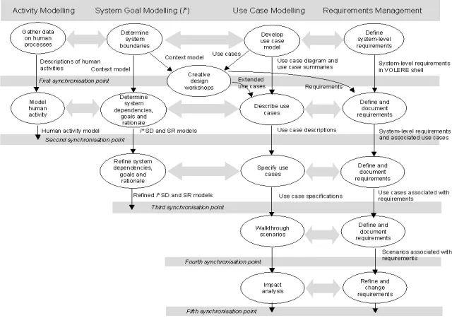
[image:4.595.143.463.417.642.2]The RESCUE (Requirements Engineering with Scenarios for User-Centred Engineering) process was developed by multi-disciplinary researchers (Maiden et al. 2003). It supports a concurrent engineering process in which different modelling and analysis processes take place in parallel. The concurrent processes are structured into 4 streams shown in Figure 1.
Each stream has a unique and specific purpose in the specification of a socio-technical system:
1. Human activity modelling provides an understanding of how people work, in order to baseline possible changes to it (Vicente 1999);
2. System modelling enables the team to model the future system boundaries, actor dependencies and most important system goals (Yu & Mylopoulos 1994); 3 . Use case modelling and scenario-driven walkthroughs enable the team to
communicate more effectively with stakeholders and acquire complete, precise and testable requirements from them (Sutcliffe et al. 1998);
4. Managing requirements enables the team to handle the outcomes of the other 3 streams effectively as well as impose quality checks on all aspects of the requirements document (Robertson & Robertson 1999).
Sub-processes during these 4 streams are co-ordinated using 5 synchronisation stages that provide the project team with different perspectives with which to analyse system boundaries, goals and scenarios. These stages are implemented as synchronisation checks described later in the paper that are applied to the models at each stage. The next sections describe each of the 4 streams in more detail.
3.1 Human Activity Modelling
In this RESCUE stream the project team develops an understanding of the current socio-technical system to inform specification of a future system. Activity modelling focuses on the human users of the technical system, in line with the principle of human-centred automation (ICAO 1994). To do this the project team must first understand the controllers’ current work – its individual cognitive and non-cognitive components and social and co-operative elements - to specify the technical systems that can better support that work. Introducing artefacts, tools or procedures into the work domain changes the way in which people work and process information. It also brings about changes in the cooperative, and possibly organisational structures that are related to the new system. The stream consists of two sub-processes – gathering data about and modelling the human activity. Figure 2 describes 2 actions that make up one human activity description – how runway controllers at Heathrow give line-up clearance to aircraft. Different aspects of the model are linked to the scenario as a whole or each action, thus providing a structured but flexible description of current work practices.
Goals: Decision made to when the next aircraft can line up, Pilot given line-up clearance, Strip
positioned correctly in the bay, LVP or MDI procedures adhered to, if in effect
1. Departure/Air controller decides which aircraft can next line up and when
Resources - strip
Physical actions - touch strip, look at airfield, aircraft, holding point and runway, move to look out of window
up clearance sequence, understand current airspace, runway and capacity situation
2. Runway ATCo calls Pilot and gives line up clearance
Resources - strip, radio, headset
Physical actions - touch strip, flick radio transmission switch, look aircraft, runway and holding point, move to look out of window
Communication - talk to pilot, issue clearance, provide information Cognitive actions - read strip information, validate visually,
Figure 2. Part of the DMAN Human Activity Model
One key concept in an activity model is goals - the desired states of the system. Goals may be: (i) high-level functional goals relating to the system as a whole, or local goals relating to particular tasks; (ii) individual goals, relating to single actors, or collective goals, relating to teams of actors; (iii) prescribed goals or non-prescribed goals. Other aspects to describe in a model include human actors - people involved in system; resources – means that are available to actors to achieve their goals, for example flight strips and information about a flight; resource management strategies – how actors achieve their goals with the resources available, for example writing down flight information on the flight strips; constraints - environmental properties that affect decisions, for example the size on the flight strip bay, which limits the number of strips to work with; actions - undertaken by actors to solve problems or achieve goals; contextual features – situational factors that influence decision-making, for example priorities are given to incoming aircraft. Data describing these concepts is structured into the activity descriptions such as the one presented in Figure 2.
3.2 System Modelling
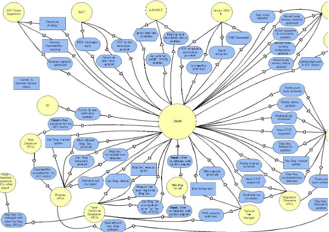
In this RESCUE stream the project team models the future system’s actors (humans and otherwise), dependencies between these actors and how these actors achieve their goals, in order to explore the boundaries, architecture and most important goals of the socio-technical system. RESCUE adopts the established i* approach (Yu & Mylopoulos 1994) but extends it to model complex technical and social systems, establish different types of system boundaries, and derive requirements. i * is an approach originally developed to model information systems composed of heterogeneous actors with different, often-competing goals that nonetheless depend on each other to undertake their tasks and achieve these goals – like the complex socio-technical systems found in ATM.
The systems modelling stream requires 3 analyses to produce 3 models. The first is a context diagram, similar to the REVEAL process (Praxis 2001) but extended to show different candidate boundaries based on different types of adjacent actors (Robertson & Robertson 1999). The result is an extended context model with typed actors that provides a starting point for i* system modelling.
TACT and A-SMGCS), and human roles that depend on DMAN to do their work (e.g. Runway ATCO and Departure Clearance ATCO). For example, the SD model specifies that DMAN depends on TACT to achieve the goal CTOT and slot messages updated, and A-SMGCS depends on DMAN to undertake the task update taxi time estimates. Likewise, DMAN depends on the Tower Departure Sequencer ATCo to have the departure sequence manual update, and the Departure Clearance ATCo depends on DMAN to achieve the soft goal workload not increased.
Figure 3. Part of the SD Model for DMAN.
RESCUE provokes the team to ask important questions about systems boundaries by re-expressing them in terms of the goal dependencies between actors on either side of a boundary. Actors with goals that the team will seek to test for compliance are, by definition, part of the new system. Such re-expression also leads to more effective requirements specification by referring to named actors that will be tested for compliance (e.g. “The controller using DMAN shall have access to the departure sequence”). It also suggests a first-cut architecture and functional allocation for the socio-technical system by defining which actors undertake which tasks.
negatively to the achievement of an important soft goal – that workload should not be increased. Furthermore, to do the issue line-up clearance task, the Runway ATCO depends on the resource flight information from the electronic flight strip.
This stream provides key inputs to the managing requirements and scenario-driven walkthroughs. Goals and soft goals in i* SR models become requirements in the managing requirements stream. Context and i* models define the system boundaries essential for use case modelling and authoring. The i* SR models define goal and task structures that suggest skeletal use case descriptions to refine the scenario-driven walkthroughs stream.
3.3 Scenario-driven Walkthroughs
In this RESCUE stream the team writes use cases then generates and walks through rich scenarios to discover and acquire stakeholder requirements that are complete, precise and testable. It uses the research-based ART-SCENE environment, which supports the automatic generation of scenarios from use case descriptions and systematic scenario walkthroughs to discover, acquire and describe requirements. The ART-SCENE environment was successfully to discover requirements for the CORA-2 system (Mavin & Maiden 2003). In this paper we focus on 2 out of the 5 sub-processes.
The first sub-process is use case modelling (Jacobson et al. 2000) that we have extended to model and investigate different system boundaries identified in the context model. The outcome is a use case model with use cases and short descriptions that are inputs into use case authoring. The DMAN use case diagram specifies human actor roles and their associations with 13 use cases and one abstract use case.
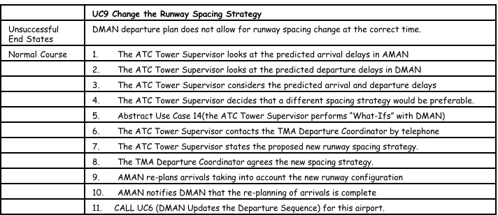
In the second sub-process the team writes detailed use case descriptions using the structured templates derived from use case best practice (e.g. Cockburn 2000). To write each description the team draw on outputs from the other streams – activity models, i* strategic rationale models, stakeholder requirements, and innovative design ideas from the creativity workshops. Once each use case description is complete and agreed with the relevant stakeholders, the team produce a use case specification from it, and parameterise it to generate scenarios automatically from each description. Part of a use case description is shown in Figure 4.
UC9 Change the Runway Spacing Strategy
Date 16 October 2003 Source Stage 1 Document
Actors ATC Tower Supervisor, Tower Departure Sequencer ATCO, TMA Departure Co-ordinator, AMAN, Tower Departure Sequencer ATCO (other airports), ATC Tower Supervisor (other airports), Tactical Flow Manager.
Problem
Statement (now) Integrate runway spacing strategy into departure planning process Triggering Event An imbalance between arrival and departure delay is predicted
Assumptions We assume that the runway spacing is defined by the number of take off and landing per hour for each runway.
Successful End
UC9 Change the Runway Spacing Strategy
Unsuccessful
End States DMAN departure plan does not allow for runway spacing change at the correct time. Normal Course 1. The ATC Tower Supervisor looks at the predicted arrival delays in AMAN
[image:9.595.124.480.144.298.2]2. The ATC Tower Supervisor looks at the predicted departure delays in DMAN 3. The ATC Tower Supervisor considers the predicted arrival and departure delays 4. The ATC Tower Supervisor decides that a different spacing strategy would be preferable. 5. Abstract Use Case 14(the ATC Tower Supervisor performs “What-Ifs” with DMAN) 6. The ATC Tower Supervisor contacts the TMA Departure Coordinator by telephone 7. The ATC Tower Supervisor states the proposed new runway spacing strategy. 8. The TMA Departure Coordinator agrees the new spacing strategy. 9. AMAN re-plans arrivals taking into account the new runway configuration 10. AMAN notifies DMAN that the re-planning of arrivals is complete 11. CALL UC6 (DMAN Updates the Departure Sequence) for this airport.
Figure 4. Part of a draft DMAN use case description for UC9: Change the runway spacing strategy.
3.4 Managing Requirements
In this fourth RESCUE stream the project team documents, manages and analyses requirements generated from the other 3 streams – automation and process requirements emerging from human activity modelling, system actor goals and soft goals from i * system modelling, and requirements arising from scenario walkthroughs.
Each requirement is documented using the VOLERE shell (Robertson & Robertson 1999), a requirement-attribute structure that guides the team to make each requirement testable according to its type. Use cases and scenarios are essential to making requirements testable. Each new requirement is specified either for the whole system, one or more use cases of that system, or one or more actions in a use case. This RESCUE requirement structure links requirements to and places them in use cases and use case actions “in context”, thus making it much easier to a write a measurable fit criterion for each requirement. RESCUE requirements are documented using IBM Rational’s Requisite Pro. Outputs from other streams, such as use case, context and i*
models, are also included in the document.
4. Synchronisation Checking
Work and deliverables from RESCUE’s 4 streams are coordinated at 5 key synchronisation points at the end of RESCUE’s 5 stages, implemented as one or more workshops with deliverables to be signed off by stakeholder representatives:
1. The boundaries point, where the team establishes first-cut system boundaries and undertakes creative thinking to investigate these boundaries;
3. The generation point, where required actor goals, tasks and resources are elaborated and modelled, and scenarios are generated;
4. The coverage point, where stakeholders have walked through scenarios discover and express all requirements so that they are testable;
5. The consequences point, where stakeholders undertake walkthroughs of the scenarios and system models to explore impacts of implementing the system as specified on its environment.
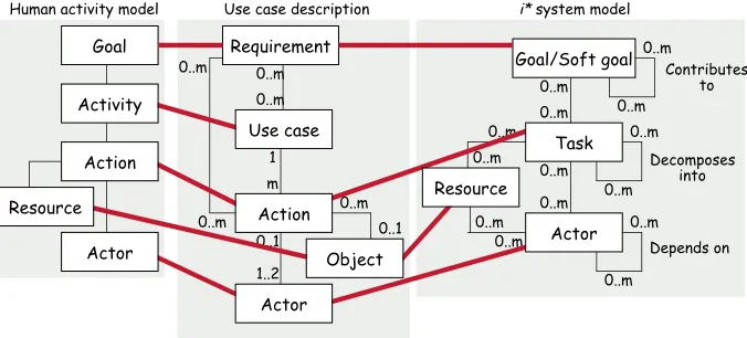
[image:10.595.127.465.312.465.2]The synchronisation checks applied at these 5 points are designed using a RESCUE meta-model of human activity, use case and i * modelling concepts constructed specifically to design the synchronisation checks. It is shown in simplified form in Figure 5 – the thicker horizontal lines define the baseline concept mappings across the different models used in RESCUE.
Figure 5. RESCUE concept meta-model as a UML class diagram showing mappings between constructs in the 3 model types.
In simple terms, the meta-model maps actor goals in human activity models to requirements in use case descriptions and i* goals and soft goals. Likewise, human activities map to use cases, and human actions to use case actions that involve human actors in use cases and tasks undertaken by human actors in i * models. Human activity resources map to i* resources and objects manipulated in use case actions, and actors in all 3 types of model are mapped. The complete meta-model is more refined. Types and attributes are applied to constrain possible mappings, for example use case descriptions and i* models describe system actors, however only human actors in these models can be mapped to actors in human activity models.
This paper reports the application of synchronisation checks at the first 2 stages. At Stage 1, data about human activities and the extended context model are used to check the completeness and correctness of the use case model. Use case summaries are used to check system-level requirements. Checks are:
Check 1.1 Every major human activity (e.g. applying resolutions) should correspond to one or more use cases in the use case model.
1 m 0..1 1..2 Requirement 0..m 0..m 0..m 0..m 0..1 0..m Goal/Soft goal 0..m 0..m 0..m 0..m 0..m 0..m 0..m 0..m 0..m 0..m 0..m 0..m 0..m 0..m Depends on Decomposes into Contributes to Goal
Human activity model Use case description i* system model
Check 1.2 Every actor identified in human activity modelling is a candidate actor for the context model.
Check 1.3 Every adjacent actor (at levels 2, 3 or 4 of the context model) that communicates directly with the technical system (level 1 in the context model) should appear as an actor in the use case diagram.
Check 1.4 The system boundary in the use case diagram should be the same as the boundary between levels 1 and 2 in the context model.
Check 1.5 Services and functions related to use cases in the use case model should map to system level requirements, i.e. high-level functional and non-functional requirements, in the requirement database.
At Stage 2, most cross checking is done in order to bring the human activity and first-cut i* models to bear on the development of correct and complete use case descriptions. Checks are:
Check 2.1 Actors, resources, goals, actions and resource management strategies identified in activity modelling should be represented in the i* SD and SR models as appropriate. Check 2.2 Actors, resources, goals, actions, differences due to variations, and differences due
to contextual features in the activity models should appear in relevant use case descriptions.
Check 2.3 Goals identified in the activity models should be reflected in the system and use case-level requirements in the requirement database
Check 2.4 All external actors in the i* SD model should correspond to actors in the use case descriptions.
Check 2.5.1 Each low level task (i.e. each task that is not decomposed into further lower-level tasks) undertaken by an actor in the i* SR model, should correspond to one or more actions in a use case description.
Check 2.5.2 Each resource used in, or produced from, a task in the i* SR model should be described in a use case description.
Check 2.5.3 Ensure that dependencies modelled in the i* models are respected in the use case descriptions, in particular:
• For goal and soft goal dependencies, the dependee must first produce whatever is needed for the depender to achieve the goal or soft goal;
• For resource dependencies, the dependee must first produce the resource that the depender needs in order for the depender to be able to use it;
• For task dependencies, the dependee must first make available whatever the depender needs in order for the depender to be able to do the task, perhaps via communication.
Check 2.6 All goals and soft-goals to be achieved by the future system according to the i* SR model should be specified in the system requirements specification and stored in the requirements database.
Check 2.7 All requirements associated with a use case in the use case template should be expressed in the system requirements specification and stored in the requirements database.
These synchronisation checks were applied in first 2 stages of DMAN, as described in the remainder of this paper.
5. DMAN Case Study
European airports. DMAN is a complex socio-technical system involving a range of human actors including tower controllers and aircraft pilots, interacting with other computer-based systems related to both airport and air movements, and supporting aircraft movement from push back from the gate to take off from the runway. The project was led by the UK’s National Air Traffic Services (NATS) and involved participants from Centre d'Etudes de la Navigation Aerienne (CENA) and City University’s RESCUE experts. The DMAN team was composed of 2 systems engineers employed by NATS and CENA and one RESCUE team member from City. It also worked with 4 UK and 4 French air traffic controllers who were seconded to the project, other NATS and CENA engineers, and software engineering academics. At the beginning of the project the City experts trained 5 NATS and CENA engineers, including the 2 in the DMAN team, in the RESCUE process using presentations and exercises. There were two days training on i* system modelling, two days on use cases, scenarios and requirements management, and one day on human activity modelling.
The project started in February 2003 and was timetabled to take 9 months to produce DMAN’s operational requirements document. Stages 2 and 3 were completed in September 2003, with stage 4 scenario walkthroughs taking place in October and November 2003. Stage 2 deliverables included a human activity model describing how UK controllers at Heathrow currently manage the departure of aircraft, a DMAN use case model and use case descriptions, system-level requirements, and some i* SD and SR models for DMAN. The human activity model was divided into 15 scenarios describing controller work, reported in a 50-page deliverable. The use case model contained 8 actors and 15 use cases. Each use case contained, on average, 13 normal course actions and 3 variations to the normal course behaviour. The majority of these use case actions were human actions or actions involving interaction with DMAN and other computer-based systems, rather than system actions. The i* SD model specified 15 actors with 46 dependencies between these 15 actors. The SR model was more complex, with a total of 103 model elements describing 7 of the 15 actors defined in the SD model.
5.1 Results from the Synchronisation Checks
[image:13.595.128.476.395.578.2]Table 1 summarises the number of checks applied, issues arising, and actions resulting from the checks. Furthermore check 2.0, which verifies that the i* SR model is consistent with its originating SD model, led to 19 additional issues to be resolved – mostly SD elements and dependency links that were missing from the SR model. Likewise, other within-stream checks, such as verifying all use case descriptions against the originating use case model were undertaken. In the remainder of this paper we focus on the more interesting results arising from the model synchronisation checks across the streams.
Table 1 shows that the synchronisation checks generated very different numbers and types of issue and actions for the team to resolve. Three checks – 1.3, 2.4 and 2.5.3 -generated nearly 92% of all identified issues. In contrast, Checks 1.5, 2.3 2.6 and 2.7 were not applied due to the model-driven approach adopted by the DMAN team – rather than establish VOLERE requirements at the same time as the models, the team chose to derive such requirements from the models at the end of stage 3, hence there were no requirements in the data base to check against. Check 2.1 was also not applied in Stage 2 due to lack of resources. The check verifies the human activity and i*
models – given the importance of scenarios in RESCUE, resources were focused on verifying the use case descriptions against other models.
Check ID Total issues
arising Issues and actions for RESCUE models Check 1.1 3 Activities without use cases, no action required. Check 1.2 4 Actors missing from context model, no action required. Check 1.3 21 Missing actors and actor links in use case model, incorrect actor
naming, needs changes.
Check 1.4 0 No issues arising between context and use case model.
Check 1.5 0 No system-level requirements.
Check 2.1 - Not applied yet – reason explained in text.
Check 2.2 1 Ambiguity detected, needs changes.
Check 2.3 0 No use case-level requirements.
Check 2.4 37 Omitted actors from use case descriptions, needs changes. Check 2.5.1 5 Omissions from use case descriptions, needs changes.
Check 2.5.2 0 All resources included.
Check 2.5.3 55 Ambiguities needing clarification, missing use case elements, dependencies between use cases discovered, use case decomposition needed, action ordering wrong, missing non-functional requirements, needs changes.
Check 2.6 0 No use case-level requirements.
[image:13.595.128.474.395.579.2]Check 2.7 0 No use case-level requirements.
Table 1. Quantitative summary of synchronisation checks applied to RESCUE models arising from stages 1 and 2.
the human activity model had been included in the use case descriptions, and one issue arose. The activity model revealed the importance of removing flights completely from the departure sequence – activities without responding use cases and actions in the use case description. The issue led to a pending change to the use case model. Check 1.3, verifying that actors in the context model are also specified in the use case model, revealed 21 issues to synchronise. Of these 21 issues, 2 were discrepancies in actor names, 13 were missing links between the actor and the use case, and 6 actors were missing from the use case diagram. A pattern emerged. All but one of the missing actors were external software systems (e.g. FDPS and A-SMGCS) while the missing links were with human actors such as Ground ATCO. This was because of a decision to simplify the stage 1 use case model to only show primary rather than secondary actors on the use case diagram. One consequence from this decision is the result of check 2.4, which identified 37 actors that were missing from the use case descriptions. During the retrospective interview, the NATS systems engineer reported that use case descriptions provided effective mechanisms for describing detailed interaction, but at the expense of structure (“it’s always hard to see both the wood and the trees”). New mechanisms to show the overall structure of an individual use case were needed.
Checks 2.5.1 to 2.5.3 verified the use case descriptions against the i* models. Check 2.5.2 revealed no missing resources from the use case descriptions. Check 2.5.1 identified 5 SR model tasks undertaken by actors that are not described in any use case description. The tasks Departure Clearance ATCO, Ground ATCO and Runway all respect the CTOT, the Runway ATCO issues takeoff clearance, and Tower Departure Sequencer ATCO gets discrepancy between capacity and departure demand lacked corresponding actions in the use cases, suggesting omissions and further actions to synchronise the use case descriptions and i* models.
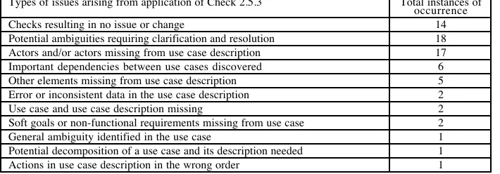
Check 2.5.3, which investigates whether use case descriptions respect i* model dependencies, revealed 55 important issues to resolve in the RESCUE models. Furthermore, only 14 of the total of 69 checks did not raise an issue, suggesting that check 2.5.3 is more useful to apply than other checks. Table 2 describes the different types of issues and their frequency of occurrence that arose from applying check 2.5.3.
Types of issues arising from application of Check 2.5.3 Total instances of occurrence
Checks resulting in no issue or change 14
Potential ambiguities requiring clarification and resolution 18
Actors and/or actors missing from use case description 17
Important dependencies between use cases discovered 6
Other elements missing from use case description 5
Error or inconsistent data in the use case description 2
Use case and use case description missing 2
Soft goals or non-functional requirements missing from use case 2
General ambiguity identified in the use case 1
Potential decomposition of a use case and its description needed 1
[image:14.595.124.479.547.671.2]Actions in use case description in the wrong order 1
Most of the 18 potential ambiguities arose from i* dependencies that require a specific ordering of actions both within and across use cases. Each ambiguity gave rise to a potential inconsistency that might arise due to un-stated assumption about the DMAN system. For example, the i* models specified that the Ground ATCo depends on DMAN to undertake the task Check MOBT (measured off-block time), and DMAN must update the MOBT. Use case UC3 specifies 2 actions: (2) The Ground ATCO looks for the flight information on the DMAN display: (3) The Ground ATCO checks that the status of the flight in DMAN is ‘OK to Push’. The two dependencies are true if we assume that MOBT information is provided by DMAN and is included in the check undertake by the ATCO. The resulting action was to establish and document the underlying domain assumption and, where necessary, change one or more of the models.
The check also revealed 17 cases of actor actions missing from the use case descriptions. For example, the i* models specified that the Runway ATCO (an actor in many use cases) depends on the Tower Departure Sequencer (TDS) ATCO to have the departure sequence followed and updated, which in turn depends on the TDS ATCO planning the departure sequence. However, no actions in which the TDS ATCO plans the departure sequence are specified in the use case descriptions. Other use case elements were also missing, for example, the i* models specified that DMAN depends on the Ground ATCO to achieve the goal of ready status updated, which in turn depends on the Ground ATCO doing the task forward ready status, but no actions corresponding to the task were specified in the use case descriptions. In 2 cases, these dependencies revealed a possible missing use case – an actor uses DMAN to evaluate capacity and demand.
Finally, the check revealed potentially important dependencies between use cases that were not explicitly identified beforehand. Again, consider one of the simpler examples. The i* models specified that the TMA Departure ATCO depends on the Runway ATCO to do the task control flight after takeoff (referred to here as task T1), which in turn depends on the Runway ATCO doing the task transfer flight to TMA Departure ATCO (referred to as task T2). Task T1 maps to action-7 in UC7, and task T2 maps to action-6 in UC13. This reveals an implied dependency between UC7 and UC13, and that action-6 in UC13 shall happen before action-7 in UC7. From this and 5 other similar dependencies, we have produced a simple model showing previously un-stated dependencies between DMAN use cases that have important implications for the timing and order of actor behaviour in the future DMAN system.
Further application of synchronisation check 2.5.3 was restricted because 23 dependencies between i* SR actor models could not be checked due to incomplete elaboration of i* SR models for all actors.
5.2 Case Study Conclusions
socio-technical systems, and these models do provide new and useful insights. In spite of this success, further method engineering work is needed to support the development of scaleable i* models. For example, constructing a single SR models specifying all actors and their dependencies is very difficult due to number and nature of these dependencies.
In the use case descriptions, the systems engineers provided more specification of human actor behaviour rather than system actor behaviour, perhaps due to the focus of socio-technical systems in RESCUE. Furthermore, to our surprise, very few system-level requirement statements were specified in the first 2 stages – instead the engineers were satisfied to develop and agree requirements models in the form of use case descriptions and i* models from which approximately 220 requirement statements have subsequently been derived.
The RESCUE synchronisation checks required resources to apply, due primarily to the degree of human interpretation of the models needed. Furthermore, some synchronisation checks were more effective than others at revealing insights into the DMAN specification. Synchronisation checks often resulted in further knowledge elicitation and document (specification of the ‘world’ in REVEAL terms) to resolve potential model ambiguities. Finally, synchronisation checks appeared to fall into 2 basic types: (i) synchronisation of models based on their first-order properties often related to naming conventions (e.g. check 1.3), and: (ii) synchronisation of models based on their derived properties, such as in check 2.5.3, which leads to in-depth verification of the use case descriptions using i* actor and element dependencies. These latter types of checks appear to be more useful to the engineers.
6. Discussions and Future Work
This paper describes intermediate results from an industrial case study that applied and integrated established and research requirements modelling techniques to a complex socio-technical system in air traffic management. It reports 2 major innovations: 1 . New requirements modelling techniques namely i*, with simple process
extensions, can be applied effectively to model socio-technical systems;
2 . The analysis of these models combined in the RESCUE stream and synchronisation structure shown in Figure 1 revealed important insights that are unlikely to have been obtained using other modelling techniques.
This DMAN case study also has implications for the multi-disciplinary requirements and design teams advocated by other authors (e.g. Viller & Sommerville 1999 for the ATM domain). The DMAN team was composed of engineers with systems and software rather than human factors backgrounds, and yet adequate training and methodology enabled the production of human activity models that effectively underpinned the development and analysis of the system models and were praised by the client.
Future research will refine and formalise the specification of the synchronisation checks, with a view towards introducing software tool support for model synchronisation. Given the need for human interpretation, we believe that software tools will be limited to detecting and ranking candidate issues in pairs of models – issues that engineers with considerable domain expertise will still have to resolve. In this sense, we view our work as different to ongoing research of viewpoints (e.g. Nuseibeh et al. 2003) and inconsistency management (e.g. Nentwich et al. 2003)., that is increasing formal specification of system requirements and automation of development processes. The advantage of RESCUE here is that it implements existing and tried-and-tested modelling techniques, limited between-model synchronisation based on simple concept meta-models and types, and guided synchronisation strategies for engineers to adopt.
Acknowledgements
The authors acknowledge the support from Eurocontrol, NATS and Sofeavia/CENA in the DMAN project.
References
Cockburn A., 2000, ‘Writing Effective Use Cases’, Addison-Wesley Pearson Education. De Landtsheer R., Letier E. & van Laamsweerde A., 2003, ‘Deriving Tabular Event-Based
Specifications from Goal-Oriented Requirements Models’, Proceedings 11th IEEE International Conference on Requirements Engineering, IEEE Computer Society Press, 200-210.
Hall J., Jackson M., Laney R., Nuseibeh B. & Rapanotti L., 2002, ‘Relating Software Requirements and Architectures using Problem Frames’, Proceedings 10th International Joint Conference on Requirements Engineering’, IEEE Computer Society Press, 137-144. ICAO, 1994, ‘Human Factors in CNS/ATM systems. The development of human-centred
automation and advanced technology in future aviation systems’ ICAO Circular 249-AN/149.
Jacobson I., Booch G. & Rumbaugh J., 2000, ‘The Unified Software Development Process’, Addison-Wesley.
Liu L., Yu E. & Mylopoulos J., 2003, ‘Security and Privacy Requirements Analysis within a Social Setting’, Proceedings 11th IEEE International Conference on Requirements
Engineering, IEEE Computer Society Press, 151-161.
Liu L. & Yu E., 2001, ‘From Requirements to Architectural Design – Using Goals and Scenarios’, Proceedings first STRAW workshop, 22-30.
Maiden N. & Gizikis A., 2001, ‘Where Do Requirements Come From?”, IEEE Software September/October 2001 18(4), 10-12.
Maiden N.A.M., Jones S.V. & Flynn M., 2003, 'Innovative Requirements Engineering Applied to ATM', Proceedings ATM (Air Traffic Management) 2003, Budapest, June 23-27 2003.
Mavin A. & Maiden N.A.M., 2003, ‘Determining Socio-Technical Systems Requirements: Experiences with Generating and Walking Through Scenarios’, Proceedings 11th International Conference on Requirements Engineering, IEEE
Computer Society Press, 213-222.
Nentwich C., Emmerich W. & Finkelstein A.C.W, 2003, ‘Flexible Consistency Checking’, ACM Transactions on Software Engineering and Methodology 12(1), 28-63.
Nuseibeh B., Kramer J., & Finkelstein A.C.W., 2003, ‘Viewpoints: Meaningful
Relationships are Difficult’, Proceedings 25th IEEE International Conference on Software Engineering, IEEE Computer Society Press, 676-681.
Praxis, 2001, ‘REVEAL: A Keystone of Modern Systems Engineering’, White Paper Reference S.P0544.19.1, Praxis Critical Systems Limited, July 2001.
Robertson S. & Robertson J., 1999, ‘Mastering the Requirements Process’, Addison-Wesley.
Rumbaugh J., Jacobson I. & Booch G., 1998, ‘The Unified Modelling Language Reference Manual’, Addison-Wesley.
Santander V. & Castro J, 2002, ‘Deriving Use Cases from Organisational Modeling’, Proceedings IEEE Joint International Conference on Requirements Engineering (RE’02), IEEE Computer Society Press, 32-39.
Sutcliffe A.G., Maiden N.A.M., Minocha S. & Manuel D., 1998, 'Supporting Scenario-Based Requirements Engineering', IEEE Transactions on Software Engineering, 24(12), 1072-1088.
Vicente, K., Cognitive work analysis, Lawrence Erlbaum Associates, 1999. Viller S. & Sommerville I., 1999, ‘Social Analysis in the Requirements Engineering
Process: from Ethnography to Method’, Proceedings 4th
IEEE International Symposium on Requirements Engineering, IEEE Computer Society Press, 6.13.
Yu E. & Mylopoulos J.M., 1994, ‘Understanding “Why” in Software Process Modelling, Analysis and Design’, Proceedings, 16th