Modified Virtually Scaling-Free Adaptive CORDIC
Rotator Algorithm and Architecture
Koushik Maharatna, Swapna Banerjee
, Senior Member, IEEE
, Eckhard Grass, Milos Krstic, and
Alfonso Troya
, Member, IEEE
Abstract—In this paper, we proposed a novel Coordinate Rotation DIgital Computer (CORDIC) rotator algorithm that converges to the final target angle by adaptively executing ap-propriate iteration steps while keeping the scale factorvirtually constantandcompletely predictable. The new feature of our scheme is that, depending on the input angle, the scale factor can assume only two values, viz.,1and1 2, and it is independentof the number of executed iterations, nature of iterations, and word length. In this algorithm, compared to the conventional CORDIC, a reduction of 50% iteration is achieved on an average without compromising the accuracy. The adaptive selection of the appro-priate iteration step is predicted from the binary representation of the target angle, and no further arithmetic computation in the angle approximation datapath is required. The convergence range of the proposed CORDIC rotator is spanned over the entire coordinate space. The new CORDIC rotator requires 22% less adders and 53% less registers compared to that of the conventional CORDIC. The synthesized cell area of the proposed CORDIC rotator core is 0.7 mm2and its power dissipation is 7 mW in IHP in-house 0.25- m BiCMOS technology.
Index Terms—Coordinate rotation digital computer (CORDIC), digital signal processing (DSP), scaling-free CORDIC, vector rota-tion, very large-scale integration (VLSI).
I. INTRODUCTION
T
HE Coordinate Rotation DIgital Computer (CORDIC) al-gorithm [1], [2] has been used for many years for effi-cient implementation of vector rotation operations in hardware. It is executed merely by table look-up, shift, and addition oper-ations. Thus, the corresponding hardware can be implemented in very economic fashion. Subsequently, it has been applied for many performance demanding applications in digital signal processing (DSP), image processing, and video technology like fast Fourier transform (FFT) [3], [4], discrete Hartley transform (DHT) [4], [5], discrete cosine transform (DCT) [4], [6], dis-crete sine transform (DST) [4], Hough transform (HT) [7]–[9],Manuscript received February 4, 2003; revised September 12, 2004. This paper was recommended by Associate Editor R. Chandramouli.
K. Maharatna is with the Department of Electrical and Electronic Engi-neering, University of Bristol, Bristol, BS8 1UB, U.K. (e-mail: [email protected]).
S. Banerjee is with the Department of Electronics and Electrical Communi-cation Engineering, Indian Institute of Technology, Kharagpur, India (e-mail: [email protected]).
E. Grass and M. Krstic are with the Communication Systems Department, IHP, 15236 Frankfurt (Oder), Germany (e-mail: [email protected]; [email protected]).
A. Troya is with Corporate Research System Technologies, Infineon Tech-nologies AG, Munich, Germany (e-mail: [email protected]).
Digital Object Identifier 10.1109/TCSVT.2005.856908
[12], graphics application [10], [11], and motion vector estima-tion [12].
In essence, a CORDIC can be operated in two different modes: the rotation and the vectoring mode. In the former mode of operation, given a vector with initial coordinate and a target rotation angle , the objective is to compute the final coordinate through a series of back-ward and forback-ward rotation of the vector in an iterative manner. In the vectoring mode, the objective is to compute the magni-tude and the phase angle of a vector given its initial and final coordinates. Table I shows the different modes of CORDIC operations in different coordinate systems where and are two constants known as scale factors for the hyperbolic and circular coordinate systems, respectively. However, despite its attractiveness, the conventional CORDIC algorithm has some drawbacks, such as slow speed, requirement of compensation of a bulk scale factor, and limited convergence range.
These drawbacks catalyze the research on the realization of high-performance special purpose CORDIC processors, and performance enhancement in algorithm as well as in the circuit level have been suggested. On the algorithmic level, the speed-up is achieved first by cleverly recoding the target angle (assumed known), and, second, by repeating some elementary rotation steps while bypassing somenot actually needed ele-mentary rotation steps [13], [25]. Although these techniques lead to a significant reduction of the number of iterations, the requirement of an extensive search procedure to find the right sequence of elementary rotation makes them computationally intensive in nature. A significant speed-up on the circuit level can be achieved using pipelined architectures and redundant arithmetic [16]–[21]. However, the determination of the direc-tion of vector rotadirec-tion is not trivial in such a number system and a false sign detection (hence a false rotation) is highly probable. To minimize the probability and the effect of false sign detection, several methods have been suggested [16], [18], [22]. Unfortunately, either they require extra iterations or hardware overhead.
In CORDIC processing, a bulk scale factor is generated that needs to be compensated. As long as all of the iterations al-lowed by a certain word length are carried out, the scale factor remains a constant and can be compensated with minimal hard-ware. However, in principle, the vector rotation for the majority of the angles lying in the coordinate space can be carried out using a smaller number of iterations by optimally choosing ap-propriate elementary rotation steps. This essentially requires by-passing or repeating some of the CORDIC iterations as was pro-posed in [13] and [25]. However, in such a case, the scale factor
TABLE I
FUNCTIONALITY OF THEGENERALIZEDCORDIC
no longer remains constant or predictable. The situation is much worse when the CORDIC works in an embedded system where other circuitry of that system (a typical example is an OFDM synchronizer for IEEE 802.11(a) standard [15]) generates data and supplies it to the CORDIC. In such a case, the CORDIC has noa prioriinformation about the actual angle of rotation and, hence, the scale factor is completely unpredictable. For its com-pensation, hardware circuitry is needed that is as complex as the original CORDIC itself. To the best of our knowledge, there is
no existing schemereported to date that can keep the scale factor constant and predictable while at the same time adaptively exe-cuting the minimum number of elementary rotation steps.
Another inherent problem of the CORDIC is that its range of convergence is small. Methods to increase the range of conver-gence use preprocessing of the input quantity or repetition of certain iteration steps [23]. However, the former approach re-sults in an overhead in hardware while the latter increases the total number of CORDIC iterations. Furthermore, the repetition of iteration steps results in a nonconstant scale factor.
In this paper, we propose an algorithmic-level improved scheme that is suitable for the rotation modeof the CORDIC (i.e., ) in a circular coordinate system. For the con-venience of nomenclature, from this point onwards, we will refer to the rotation mode of CORDIC in a circular coordinate system asCORDIC rotatoroperation.
To tackle the scale factor compensation problem, the authors have earlier proposed ascaling-freeCORDIC algorithm having a small range of convergence [4], [24], and its error performance was shown to be identical to the conventional CORDIC [4]. However, in a more general scenario like [15], this algorithm cannot be applied efficiently. Thisscaling-freeCORDIC algo-rithm is used as the baseline of the present work. The new con-tribution of the current work is: we develop a novel CORDIC ro-tator algorithm thatadaptivelyexecutes only theactually needed
elementary rotation steps to converge to the final target angle while keeping the scale factorvirtually constant(it can take the values 1 or only) andcompletely predictable. The final scale factor only depends on the actual value of the target angle and not on the number of executed iterations. On average, this adaptive selection results in about 50% reduction of compu-tations without compromising the accuracy. The convergence range of the proposed CORDIC is spanned over the entire
coor-dinate space. A novel feature of our scheme is that it is possible toeliminatetheentire arithmeticand associated hardware for the angle approximation datapath. This results in a significant reduction of hardware and power consumption. The proposed algorithm and its very large-scale integration (VLSI) architec-ture are guaranteed to work even when the CORDIC operates in an embedded system. We call the proposed algorithm vir-tually scaling-free adaptive CORDIC rotator algorithmmainly because of the nature of the scale factor. The rest of the paper is structured as follows. In Section II, a brief review of the rota-tion mode of the convenrota-tional CORDIC algorithm in a circular coordinate system and thescaling-freeCORDIC algorithm de-veloped in [4], [24] are provided. Section III outlines the method of extending the angular convergence range of thescaling-free
CORDIC rotator which leads to the newvirtually scaling-free
CORDIC rotator algorithm. In Section IV, we describe the archi-tecture of the pipelined CORDIC rotator based on the proposed algorithm and the different performance parameters of it are dis-cussed in Section V. In Section VI, the design of the processor in IHP in-house 0.25- m BiCMOS technology is described. Con-clusions are drawn in Section VII.
II. BRIEFREVIEW OF THECONVENTIONAL AND THE SCALING-FREECORDIC
A. Conventional CORDIC
The rotation of a vector in the Cartesian coordinate system can be described as (considering clockwise rotation)
(1)
where is the final vector and is the target angle of rotation. In the CORDIC algorithm, is expressed as the sum-mation of a decreasing sequence of elementary angles so that
of vector rotation for the th iteration. Substituting (2) into (1) and using (3), one may write
(4) and
(5) (6) Equations (4)–(6) are the basic working equations of the CORDIC rotator operation where and are the inter-mediate result vector and the residual angle, respectively, at the beginning of the th iteration step. From the hardware imple-mentation point of view, this vector rotation is nothing but a sequence of shift-and-add operations. However, the final result requires a scaling by a factor ( in Table I). The scale factor remains a machine constant as long as the index runs through all of the values from 0 to , i.e., when all of the allowed iteration steps are executed. However, if changes in a different manner, i.e., if some of the allowed iterations are bypassed or repeated in order to achieve a faster convergence rate or a larger convergence range, the scale factor will not remain constant and, for its compensation, one requires extra hardware and comparable postprocessing cycles.
B. Scaling-Free CORDIC Algorithm
The detailed description of the scaling-freeCORDIC algo-rithm and its error performance is provided in [4], [24]. Thus, for the sake of conciseness, here we will outline only the essen-tial features of that algorithm.
Unlike the conventional CORDIC algorithm, in the scaling-freeCORDIC algorithm, the final target angle is achieved by rotating the vector in one direction only. This means that the final target angle is approximated as apure summationof the elementary angles. These elementary rotational angles are chosen in such a manner that the length of the vector be always preserved during each of the elementary rotation and is given by (7) (using first-order approximation of sine series) and subse-quently
(8) The use of first-order approximation of sine series for defining in (7) imposes the following restriction on the allowed values of iteration index :
(9) since can only take integer values. However, for practical pur-poses, the lower bound of can be relaxed slightly and can be given by the following equation:
[image:3.594.313.538.60.335.2](10)
Fig. 1. Elementary rotational section fori < b=2.
Using (7) and (8), (since the sign of residual angle is always the same for all iteration), and clockwise rotation of the vector, (1) may be rewritten as
(11) Equation (11) is the working equation of the scaling-free
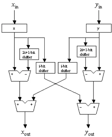
CORDIC rotator algorithm. It can be noted that, like (4), (11) can be realized in practice using only shift-and-add operations. On the other hand, contrary to (4), no scaling term appears in (11). The datapath component for implementing the operation stated in (11) is shown in Fig. 1. This can be viewed as an elementary rotational section rendering a rotation of to its input vector . It requires four shifters, two subtractors, and two adder/subtractor in the datapath. Thus, compared to the datapath of an elementary rotational section of anunscaled
CORDIC, it requires two shifters and two subtractors more. However, for the elementary rotational sections corresponding to , these extra shifters and the subtractors can be omitted as the right shift of the input quantity by
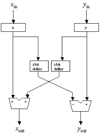
becomes machine zero. Thus, the hardware cost for each of the elementary rotational sections corresponding to these values of is exactly the same as that of the elementary rotational sections of theunscaledCORDIC. This simplified elementary rotational section is shown in Fig. 2.
Fig. 2. Elementary rotational section fori b=2.
to be developed to expand its angle computation range while preserving its scaling-free property.
III. NEWVIRTUALLY SCALING-FREE CORDIC ROTATORALGORITHM
The main idea behind the development of avirtually scaling-freeCORDIC rotator algorithm is to develop a CORDIC rotator algorithm having convergence over the entire coordinate space while staying within the general framework of thescaling-free
CORDIC. The main requirement in such a case is to extend the convergence range of the scaling-free CORDIC itself. To do this, first an argument reduction technique is used to reduce the total angular range to be computed. Second, the elementary rotational operations are carried out in an adaptive manner to enhance the rate of convergence and to force the final angle approximation error below a certain prespecified limit. In the forthcoming discussion, this scheme is explained in detail.
The main objective of the argument reduction technique is to uniquely map the results of a CORDIC rotation with a large target angle to the results of a CORDIC rotation with a relatively small target angle . To do this, we divide the four quadrants of the coordinate system into 16 equal domains each having a uniform angular span of (i.e., four domains per quadrant). Any target angle ( ve or ve) must lie in one of these 16 domains. We first examine the CORDIC rotation of an input vector with target angle lying in the first quadrant. This essentially means that lies in one of the four domains A , B , C
and D . In each domain, can be redefined in terms of another angle bounded in the interval by the following equations:
[image:4.594.310.553.419.550.2]in domain A (12)
Fig. 3. Different domains and the definition of the modified target angle() in each of them.
in domain B (13) in domain C (14) in domain D (15) This is shown in Fig. 3. Using (12)–(15) in (1), the CORDIC rotator operation on an input vector in different domains can be expressed in terms of as follows:
in domain A (16)
in domain B (17)
in domain C (18) in domain D (19) where denotes the final vector resulting from a CORDIC rotator operation with target angles lying in a certain domain indicated by .
Now denoting and as the result of CORDIC rotation for angle and respectively, (16)–(19) can be written as
(20)
(21)
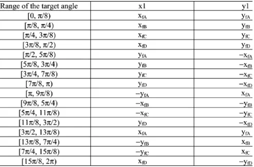
TABLE II
RESULTS OF THECORDIC ROTATOROPERATION FORDIFFERENTQUADRANTS
USING THEDOMAINFOLDINGTECHNIQUE
Thus, using the above equations, the CORDIC rotator opera-tion with target angles lying in any domain in the first quad-rant can be computed from the results of the CORDIC rotation with target angle (bounded in the interval ). This es-sentially means that the domains B, C, and D are effectively
folded back to domain A. Hence, we call this technique do-main folding. A consequence of the domain folding operation is the generation of a constant scale factor for target an-gles lying in the domains B and C which can be realized with minimal hardware using only shift and add operations. The im-portant point to be noted here is that this scale factordoes not dependon the number of executed elementary rotations, nature of elementary rotation or the machine wordlength. On the other hand, for the target angle lying in domains A and D absolutely no scaling is required. Thus, the entire operation becomes vir-tually scaling free. It is apparent from (20) to (23) that for a par-ticular target angle, rotation in only one direction (either ve or ve) is needed. Thus, the assumption that the target angle is approximated through only unidirectional sequence of vector rotation made for thescaling-freeCORDIC is also valid here. This fact can be efficiently utilized to reduce the hardware com-plexity of the proposed CORDIC rotator during its architectural level implementation. We discuss this issue in Section IV.
By exploiting the symmetry of the coordinate axes, the do-main folding technique can be extended to carry out CORDIC rotator operations with target angles lying in other quadrants as well. Table II provides a comprehensive report of the same, which shows that, depending on the quadrant in which the target angle lies, only the sign of the final vector components have changed. Thus, for computation of vector rotations with arbi-trary target angles, the first step is to detect the quadrant and domain in which it lies. Once these parameters are detected, the computation can be carried out applying the appropriate equa-tion from (20)–(23).
At this point, it is clear that, by using the domain folding
[image:5.594.41.288.102.265.2]technique, it is sufficient to consider the CORDIC operation for angles lying in the interval only. This results in a 16 argument reduction. However, this range is still beyond the range of convergence of the originalscaling-freeCORDIC ro-tator unit. Thus, to take the full advantage of thedomain folding
Fig. 4. Process of adaptive selection of the iteration steps (searching algorithm).
technique, we need to expand the range ofscaling-freeCORDIC to . This is done by choosing the iteration index for each iterationadaptivelyin accordance with the residual angle still to be computed. Owing to the scaling-free property of the basic
scaling-freeCORDIC, this repetition of some elementary rota-tion steps does not generate any new scale factor. The flexibility offered in this approach is that the final error due to the angle approximation can be tailored by setting a prespecified limit of accuracy or number of iterations. The process of adaptive selec-tion of is described in the flowchart shown in Fig. 4 where, is the prespecified error limit (being adjusted by the user). In principle, the processor stops iterations when the residual angle becomes less than . If a large value for is chosen, the number of required iterations will be small but the accuracy will suffer. On the other hand, a very small value of results in a high accuracy but requires more iterations. Thus, the choice of should be done judiciously and according to the computa-tional need of the target application.
Lemma: Only the iteration step corresponding to the smallest allowable value of gets repeated more than once while the other values of are nonrepetitive.
greater than or equal to . This is in contradiction to our initial assumption. Thus, it can be concluded that no elementary rotation steps corresponding to can get repeated.
However, if , then the elementary rotation steps corresponding to will be executed times. The search algorithm employed for the adaptive selection of appropriate elementary rotational steps (shown in Fig. 4) is a simple comparison with that can be implemented with min-imal hardware. However, in the actual pipelined implementation this comparison is practicallynot neededowing to the one-sided rotation property of the proposed algorithm. In Section IV, we will describe this in more detail.
IV. ARCHITECTURE OF THECORDIC ROTATOR
The architecture of the new CORDIC rotator can be derived by a suitable hardware mapping of the algorithm described above. For sake of clarity, the implementation of a 16-b CORDIC rotator is described here as an example. All of the discussions presented in this section can be generalized for an
-bit CORDIC rotator as well.
For the design of the architecture, we have assumed that the decimal 1 is represented as 0 100 000 000 000 000. However, it is possible to choose a different definition also. Now, be-cause of thedomain folding, all of the angles lying in the co-ordinate space are effectively mapped into the range . Thus, the effective maximum target angle that has to be com-puted is rad. Using the definition of decimal 1 stated above, this angle can be represented in binary format as 0 001 100 100 100 010 with an error of . Thus, from the implementation point of view, for representing the absolute value of any angle lying in the modified convergence range one can omit the first three most significant bits (MSBs) and can use the 13 least significant bits (LSBs). In our architecture, we use this fact to reduce the total computation in the angle approxima-tion datapath.
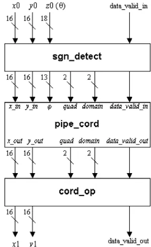
In principle, our design consists of three basic sections: the sign/domain detection circuitry, the basic CORDIC processor having convergence range of , and the output circuitry. This is shown in Fig. 5.
[image:6.594.350.502.64.313.2]Sign/Domain Detection Circuitry: The sign/domain de-tection circuitry (designated as sgn_detect in Fig. 5) has two 16-b-wide data word for and and an 18-b-data word for . We assume that the largest angle that can be as-signed to the primary input lies within the range . According to our number representation, the value of is 011001001000011111, which is an 18-b number. Keeping this fact in mind, we keep the 18-b word length for input. Any negative angle will also fall within this range and thus can be translated to an appropriate positive angle. The principal job of the sign/domain detection circuitry is to detect the sign and domain of the target angle and subsequently, it appliesdomain foldingtechnique to derive the 13-b unsigned representation of the modified target angle . It also generates two 2-b signals, namelydomainandquad. While the quadsignal indicates on which quadrant the original target angle lies, thedomainsignal indicates the corresponding domain in the first quadrant on
Fig. 5. Architecture of the complete CORDIC rotator.
which it has been folded back. The entire operation in this unit is performed in one clock cycle.
Basic Pipelined CORDIC Rotator Unit: The second sec-tion of our design is the basic CORDIC rotator unit having an internal wordlength of 16-b and a convergence range of (designated as pipe_cord in Fig. 5). The scaling-free
CORDIC units shown in Figs. 1 and 2 acts as the elementary rotational sections in the present system. We implement the basic CORDIC rotator in pipelined fashion, thereby unfolding the iteration steps. With this approach, the shifters for each elementary rotational section become simple wire connections and effectively each elementary rotor section consumes a hardware area equivalent to four adder/subtractor units. On the other hand, as has been mentioned earlier, theoretically, for the elementary rotational sections corresponding to (i.e., ), the hardware cost is equivalent to two adder/subtractor units. The allowed values of the CORDIC iteration in this case are [from (10)]. However, in our number representation scheme, shifting of any operand by 15 b to the right results in the retention of the sign bit only. Thus, for practical purposes one can omit the elementary rotational section corresponding to from the design. On the other hand, following the same argument the two -bit shifters and the corresponding adders can also be removed from the elementary rotational section . Thus, we have used four adder/subtractors for each of the elementary rotational sections corresponding to and two adder/subtractors for each of the elementary rotational sections corresponding to . In the forthcoming section, we will show that these assumptions do not introduce higher numerical errors compared to that of the conventional CORDIC.
TABLE III
RELATIONSHIPBETWEEN THEPOSITION OFLOGIC“1”IN THEREPRESENTATION OFAND THEAPPROPRIATEELEMENTARYROTATIONALSECTIONS
Fig. 6. Architecture of the basic CORDIC rotator pipeline.
to is used once. The maximum angle that can be computed using such an arrangement is approximately 25 and thus covers our modified convergence range. Two’s comple-ment arithmetic is used for each of these elecomple-mentary rotational sections. To make the pipeline completely balanced in terms of operating speed, we concatenate the elementary rotational sec-tions corresponding to (7, 8), (9, 10), (11, 12), and (13, 14), where, the elementary rotational sections within the parenthesis form a single pipeline stage each. With this special arrangement the basic CORDIC rotator pipeline becomes 12 stages long and the hardware complexity of each of these stages is equivalent to four 16-b adders.
The data and the information about the quadrant (signalquad) and domain (signaldomain) of the initial vector detected in the sgn_detect module are transferred synchronously between two successive sections of the pipeline in a local register transfer manner. This means that each of the data in different sections of the pipeline has atokenattributed to it that carries the infor-mation about the initial quadrant and domain of that particular data.
It has been mentioned earlier that in our algorithm, we ap-proach the target angle by rotating the vector always in the same direction. Thus, in essence we approximate the target angle as a pure summation of . As a result, the appropriate elemen-tary rotational sections to be selected for a particular target angle
have a one-to-one correspondence with the position of a logic “1” in the 13-b unsigned representation of . Table III summa-rizes the relationship between the position of a logic “1” in the representation of and the corresponding active elementary ro-tational sections. As an example, let us consider that
register of the respective shift register array. The structure of the basic pipelined CORDIC processor using this arrangement is shown in Fig. 6 where is the index of the elementary rotational sections of the pipeline. In Fig. 6, the solid lines indicate the boundary of each of the elementary rotational sections whereas the dotted lines indicate the concatenated elementary rotational stages.
This arrangement essentially mimics the search algorithm and eliminates the comparison of with and and the associated computation of new residual angle shown in Fig. 4. Thus, attendant hardware in the angle approximation datapath can beomitted completely. It is to be noted that, for the conventional CORDIC algorithm the target angle is approx-imated by a to-and-fro motion of the vector, and therefore the simple arrangement described here for the elimination of the arithmetic computation in the angle approximation datapath cannot be adopted there directly.
Output Unit: The last unit of the complete CORDIC rotator is the output unit designated as cord_op in Fig. 5. The circuit consists of two fixed scaling units of and two adder/sub-tractor units. Each of the scaling units is realized using five 16-b adders. Thus, the overall hardware complexity of this unit is equivalent to twelve 16-b adders. Depending on thedomainand
quadsignals this unit assigns the sign, applies either a scaling of or simply passes the output vector emerging from the basic pipelined CORDIC it to the primary output [according to (20)–(23) and Table II]. All of the operations in the output unit are completed in one clock cycle.
V. PERFORMANCEEVALUATION ANDCOMPARISON
For evaluating the performance of the proposed CORDIC rotator algorithm and architecture, we mainly concentrate on two issues, error in the calculation of the and datapath and the area requirement for the complete CORDIC rotator. Here, we have not concentrated on the optimization of the number of adder/subtractors in the elementary rotational sections. Our main view is to consider the amount of hardware the proposed algorithm needs in itsnaturalway. However, it is possible to re-duce the number of adder/subtractors using different optimiza-tion schemes. Apart from these two issues, we also explore the possible advantage of the proposed architecture in terms of speed and power.
Error Analysis: In the implementation of a digital circuit, two main error sources exist: quantization of the input word and the truncation or cut-off rounding error due to the finite wordlength of arithmetic operations. However, for a CORDIC implementation, a third source of errors comes from how closely one can drive the variable to zero, i.e., how closely the target angle is approximated. Since the proposed CORDIC rotator obeys the essential characteristics of the scaling-free
CORDIC unit, its angle approximation error is also the same as the latter. Thus, in our case the angle approximation error is
[4].
However, the more dominant error in the hardware implemen-tation of a CORDIC is the truncation error generated after each elementary rotation operation. This error gets accumulated at every section of the pipeline and dominates the final error in the
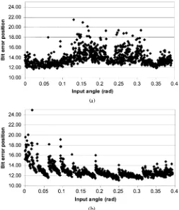
(a)
[image:8.594.302.555.63.360.2](b)
Fig. 7. (a) Numerical errors in thexdatapath. (b) Numerical errors in they datapath.
calculation for the and values ( and , respectively, in our case).
To find out the combined effect of these three error mecha-nisms on the proposed architecture, we first generate a pseudo-random sequence of angles lying within our modified conver-gence range . Using these angles as the inputs, the results for the and datapath of a Matlab model of ideal CORDIC function (1) is compared with the results for the and data-path of the VHDL coded proposed CORDIC rotator. The corre-sponding errors in terms of the decimal bit position are shown in Fig. 7. It is apparent from Fig. 7 that the upper bound of the errors for the and datapath is at the 12th decimal bit position. However, in order to achieve -bit accuracy for the conventional CORDIC operation considering every form of quantization and truncation errors, one needs to use -bit data word length [14]. Thus, using 16-b word length, in case of the con-ventional CORDIC, the achievable upper bound of the error is approximately 10 b. This fact shows that the upper bound of the error resulting from the proposed CORDIC rotator method is
Area Requirement: In the proposed CORDIC rotator archi-tecture, the basic CORDIC pipeline is 12 sections long and each of these sections requires four 16-b adders. The sign/domain de-tection unit needs two 16-b adders and two comparators. How-ever, for both of the comparators, one of the input variables is constant. The hardware complexity of each of these comparators is estimated conservatively as equivalent to one 4-b adder. The output unit consists of two 16-b adders and two scaling units that are responsible for post-scaling by . Each of these scaling units consists of five 16-b adders. Thus, in our implementation the total area of the complete CORDIC rotator is approximately equivalent to 62 16-b adders and two 4-b adders. Considering one -bit adder is equivalent to full adders, the area of the proposed CORDIC rotator is equivalent to 1000 full adders.
In the conventional 16-b CORDIC implementation, the number of 16-b adders is 48 (including the angle approx-imation datapath). Here, we have assumed that the angle approximation datapath is 16 b wide like the and data-path. For compensation of the scale factor using shift-and-add technique one requires another 32 16-b adders. Thus, the com-plete conventional CORDIC structure needs 80 16-b adders altogether, which is equivalent to 1280 full adders. Thus, the proposed design requires approximately 22% less full adders compared to the conventional one. On the other hand, if the scale factor compensation network consists of two 16 16-b multiplier and each of them has 232 full adders ( multiplier requires full adders and half adders) then the complete area of the conventional CORDIC processor is equiv-alent to 1232 full adders. This is still 19% higher compared to the proposed design.
In our implementation, the total number of registers required is 597. The number of registers that are required for the con-ventional CORDIC algorithm including scale factor compensa-tion circuitry is 1280. Thus, our design needs 53% less registers compared to the conventional CORDIC.
Speed: The basic CORDIC rotator pipeline in our imple-mentation is 12 stages long. Including the sign/domain detection section and the output section, the complete CORDIC pipeline length is 14 stages long. Thus, the latency of the processor is 14 clock cycles. The throughput of the proposed CORDIC ro-tator is one complete set of results/clock cycle. However, in this implementation, we do not need to carry out any arithmetic op-eration in the angle approximation datapath when the data is in the CORDIC pipeline. Thus, in this approach, one needs not to spend any time for the detection of sign of the direction of ro-tation (equivalently, sign of the residual angle) and subsequent approximation of the angle approximation datapath for a partic-ular elementary rotational section. This implies that there is a possibility of significant speed enhancement of the processor.
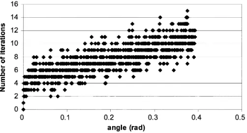
[image:9.594.302.553.65.200.2]Number of Iterations: In the proposed architecture, the ap-propriate elementary rotational sections are selected adaptively and the data processing is carried out only at those particular el-ementary rotational sections whereas, the other sections are by-passed. This operation in principle implies that, on an average, total number of iterations required for the proposed CORDIC rotator is smaller than that of the conventional CORDIC. To
Fig. 8. Number of iterations required for the proposed CORDIC rotator for different target angles.
verify this, we once again used the pseudorandom angle se-quence that lies within the modified convergence range gen-erated earlier. The number of iterations corresponding to each of these angles is shown in Fig. 8. It is apparent from Fig. 8 that the maximum number of iterations (15) is needed for the angle 21.482 (0.3749 rad), where its unsigned binary repre-sentation is 1 011 111 111 111. For all other angles, the required number of iterations is smaller compared to that of the conven-tional CORDIC which is supposed to take 16 iterations (without scaling iterations) for each angle for the same order of accuracy. However, from Fig. 8, we calculated that the average number of iteration executed by the proposed CORDIC rotator is ap-proximately 8, which is 50% less than that of the conventional CORDIC.
Power: The power consumption of a digital circuit is a func-tion of silicon area and the number of arithmetic computafunc-tions given a fixed frequency and operating voltage. It is already shown that the proposed CORDIC rotator requires less area compared to the conventional CORDIC and requires a smaller number of iterations to converge to the final target angle. The elimination of the angle approximation datapath results in a further reduction of arithmetic operations in the proposed CORDIC rotator. Thus, it can be expected that the architec-ture will consume less power compared to the conventional CORDIC processor.
Applicability of Redundant Arithmetic: For further speed up of the proposed CORDIC rotator, the redundant arithmetic can be used. Here, the and datapath can be represented in re-dundant format whereas, the target angle can be represented in conventional 2’s complement format. Since the logic “1” in the unsigned binary representation of the modified target angle acts only as an enable signal for the appropriate rotational stages of the pipeline, the arithmetic computation (addition or subtrac-tion) inside those stages can conveniently be carried out in con-stant time using redundant arithmetic. In this way, the principle problem of sign detection of the residual angle can be avoided while enjoying the high-speed advantage of it.
TABLE IV
COMPARISON OF THEPROPOSEDALGORITHMWITHTWOOTHERSIMILARALGORITHMS
TABLE V
COMPARISON OF THEPROPOSED16-b CORDIC ROTATORARCHITECTUREWITHSOMEOTHERPUBLISHEDREDUNDANTARITHMETICBASEDARCHITECTURES
in [25] uses a predefined fixed number of iterations. In all three cases, the number of executed iteration is less than that required for the conventional CORDIC algorithm. The principle advan-tage of the proposed algorithm is that, within the family of se-lective iteration, this is theonly onethat isvirtually scaling free. The other algorithms require scale factor compensation owing to their selective nature. Thus, the final hardware requirement and the number of iterations including scaling iteration is min-imum in the proposed algorithm. The second advantage of the proposed one is that it does not require complicated search al-gorithm like the others. In principle, the appropriate elemen-tary rotational sections are automatically selected using the bi-nary representation of the target angle. This results in significant hardware and power reduction compared to the others. Third, the proposed algorithm is guaranteed to work even when the target angle is not known in advance. Even for this case also, practically no search algorithm is needed. Regarding the error performance, the proposed algorithm gives same order of angle approximation error as that of the conventional CORDIC. Com-bining all of these facts, it is expected that the proposed algo-rithm will outperform the referenced ones in terms of speed, area, and power.
As a matter of interest, we also compare the hardware require-ment of the proposed CORDIC rotator with some other redun-dant CORDIC implementation in Table V. For comparison on a uniform base, we have only considered the hardware require-ment of the basic CORDIC pipeline without hardware for the scale factor compensation. It is apparent that the proposed one requires less number of equivalent full adders and registers com-pared to the others.
Drawbacks and General Discussions: Though the proposed algorithm eliminates the problem of adaptive selection of el-ementary rotation steps in conjunction with keeping the scale factor virtually constant, it is not also free of problem. The main problem is that the selection of largest elementary angle in this scheme depends on the wordlength [(10)]. This angle becomes
increasingly smaller as the word length increases. Consequently, one needs to incorporate more sections of this elementary angle in the pipeline. As a result, the conventional CORDIC is ex-pected to outperform the proposed one in terms of hardware re-quirement when the wordlength reaches 20 b. However, in that case, a hybrid scheme can be adopted to bring down the hard-ware cost. One may use some conventional CORDIC iteration (only unidirectional) to bring down the residual angle within the range of thescaling-freeCORDIC iterations and then employ the proposed algorithm. In such a case, the scale-factor com-pensation circuitry required for those conventional CORDIC sections has to be integrated into the corresponding elemen-tary rotational sections to avoid the generation of final scale factor and to maintain thevirtually scaling-freeproperty of the proposed algorithm. However, in general, hardware implemen-tation with 16-b word length encompasses a vast application space, and for that the proposed CORDIC rotator shows sig-nificantly improved performance compared to the conventional CORDIC.
VI. IMPLEMENTATION OF THECORDIC ROTATOR
For the design of the processor, the IHP in-house design kit is used. The CORDIC rotator is first modeled in VHDL and sim-ulated using Mentor Graphics’ Modelsim simulator. After the functional verification, Synopsys’ Design Analyzer is used to synthesize the circuit for our in-house 0.25- m BiCMOS tech-nology with a target clock frequency of 20 MHz. The cell area of the complete processor after synthesis is 0.7 mm , which is equivalent to 24.7 k inverter gates in this technology. The power consumption reported by Synopsys’ Design Analyzer is 7 mW at 2.5-V supply voltage.
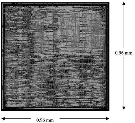
Fig. 9. Layout of the CORDIC rotor core.
extracted from the layout is resimulated including the Standard Delay File (SDF) using Modelsim, which confirms the correct behavior of the processor. The layout of the CORDIC rotator core is shown in Fig. 9.
VII. CONCLUSION
In this paper, we presented a novel algorithm and architecture of a special rotational CORDIC processor that operates in the circular coordinate system and has an unlimited angular conver-gence range. The algorithmadaptively selectsthe appropriate iteration steps and thus converges to the target angle executing aminimum numberof iterations. On average, the number of it-erations for the proposed method is about 50% less compared to the conventional CORDIC. The accuracy of the results is not compromised. The novel property of the proposed algorithm is that, unlike the conventional and previously reported CORDIC, the adaptive selection of the iteration steps hasno influenceon the final value of the scale factor, and thus it is possible to by-pass theactually not needediteration steps while keeping the scale factor virtually constant. Compared to the conventional CORDIC, in our scheme, the number of adders is reduced by 22%, and 53% fewer registers are needed. Moreover, the hard-ware requirement for the sign/domain detection circuitry is very small compared to that used for other argument reduction tech-niques.
Based on this algorithm, a 16-b pipelined CORDIC processor core was designed using IHP in-house 0.25- m BiCMOS tech-nology. The cell area of the CORDIC processor core is equiva-lent to 24.7 k inverter gates. The latency of the processor is 14 clock cycles. The power consumption of the CORDIC core re-ported by the synthesis tool is 7 mW. These figures show that the processor consumes little silicon area and is suitable for high-speed low-power applications. Currently, this CORDIC is used in an OFDM baseband processor for a wireless modem compliant with IEEE 802.11a [15].
REFERENCES
[1] J. E. Volder, “The CORDIC trigonometric computing technique,”IRE Trans. Electron. Comput., vol. EC-8, no. 3, pp. 330–334, Sep. 1959. [2] J. S. Walther, “A unified algorithm for elementary functions,” inProc.
Joint Spring Comput. Conf., vol. 38, Jul. 1971, pp. 379–385.
[3] E. F. Deprettere, P. Dewilde, and R. Udo, “Pipelined CORDIC archi-tectures for fast VLSI filtering and array processing,” inProc. ICASSP, 1984, pp. 41 A 6.1–41 A. 6.5.
[4] K. Maharatna, A. S. Dhar, and S. Banerjee, “A VLSI array architecture for realization of DFT, DHT, DCT and DST,”Signal Process., vol. 81, pp. 1813–1822, 2001.
[5] E. L. Zapata and F. Arguello, “A VLSI constant geometry architecture for the Hartley and Fourier transform,”IEEE Trans. Parallel Distrib. Syst., vol. 3, no. 1, pp. 58–770, Jan. 1992.
[6] M. C. Mandal, A. S. Dhar, and S. Banerjee, “Multiplierless array ar-chitecture for computing discrete cosine transform,”Computers Elect. Eng., vol. 21, no. 4, pp. 327–333, 1994.
[7] J. D. Bruguera, N. Guil, T. Lang, J. Villalba, and E. L. Zapata, “CORDIC-based parallel/pipelined architecture for hough transform,”
J. VLSI Signal Process., vol. 12, pp. 207–221, 1996.
[8] D. Timmermann, H. Hann, and B. J. Hosticka, “Hough transform using CORDIC method,”Electron. Lett., vol. 25, no. 3, pp. 205–206, 1989. [9] K. Maharatna and S. Banerjee, “A VLSI array architecture for hough
transform,”Pattern Recognit., vol. 34, pp. 1503–1512, 2001. [10] H. Yoshimura, T. Nakanishi, and Y. Yamaguchi, “A 50 MHz CMOS
geometrical mapping processor,”IEEE Trans. Circuits Syst., vol. 36, no. 10, pp. 1360–1363, Oct. 1989.
[11] K. Maharatna and S. Banerjee, “CORDIC based array architecture for affine transformation of images,” inProc. Int. Conf. Communications, Computers and Devices, vol. II, Kharagpur, India, Dec. 2000, pp. 645–648.
[12] H. L. Li and C. Charkrabarti, “Hardware design of a 2-D motion estima-tion system based on hough transform,”IEEE Trans. Circuits Syst. II, vol. 45, no. 1, pp. 80–95, Jan. 1998.
[13] Y. H. Hu and S. Naganathan, “An angle recoding method for CORDIC algorithm implementation,”IEEE Trans. Comput., vol. 42, no. 1, pp. 99–102, Jan. 1993.
[14] K. Kota and J. R. Cavallaro, “Numerical accuracy and hardware trade-offs for CORDIC arithmetic for special purpose processors,”IEEE Trans. Comput., vol. 42, no. 4, pp. 769–779, Jul. 1993.
[15] M. Krstic, A. Troya, K. Maharatna, and E. Grass, “Optimized low-power synchronizer design for the IEEE 802.11(a) standard,” inProc. ICASSP. [16] N. Takagi, T. Asada, and S. Yajima, “Redundant CORDIC methods with a constant scale factor for sine and cosine computation,”IEEE Trans. Comput., vol. 40, no. 5, pp. 989–995, Sep. 1991.
[17] J. A. Lee and T. Lang, “Constant-factor redundant CORDIC for angle calculation and rotation,”IEEE Trans. Comput., vol. 41, no. 8, pp. 1016–1025, Aug. 1992.
[18] J. Duprat and J. M. Muller, “The CORDIC algorithm: New results for fast VLSI implementation,”IEEE Trans. Comput., vol. 42, no. 2, pp. 168–178, Feb. 1993.
[19] D. Timmermann and S. Dolling. Unfolded Redundant CORDIC VLSI Architectures With Reduced Area and Power Consumption. [Online]. Available: http://www-md.e-technik.uni-rostok.de/ma/dtim/vlsi97.pdf [20] H. Dawid and H. Meyr, “The differential CORDIC algorithm: Constant
scale factor redundant implementation without correcting iterations,”
IEEE Trans. Comput., vol. 45, no. 2, pp. 307–318, Mar. 1996. [21] E. Antelo, J. D. Bruguera, and E. L. Zapata, “Unified mixed radix 2–4
redundant CORDIC processor,”IEEE Trans. Comput., vol. 45, no. 5, pp. 1068–1073, Sep. 1996.
[22] D. S. Phatak, “Double step branching CORDIC : A new algorithm for fast sine and cosine generation,”IEEE Trans. Comput., vol. 47, no. 3, pp. 587–602, May 1998.
[23] X. Hu, R. G. Harber, and S. C. Bass, “Expanding the range of conver-gence of the CORDIC algorithm,”IEEE Trans. Comput., vol. 40, pp. 13–21, Jan. 1991.
[24] A. S. Dhar and S. Banerjee, “An array architecture for fat computation of discrete hartley transform,”IEEE Trans. Circuits Syst., vol. 38, no. 9, pp. 1095–1098, Sep. 1991.
Koushik Maharatnareceived the M.Sc. degree in electronic science from Calcutta University, Calcutta, India, in 1995 and the Ph.D. degree from Jadavpur University, Calcutta, India, in 2002.
From 1996 to 2000, he was involved in projects sponsored by the Government of India undertaken at the Indian Institute of Technology (IIT), Kharagpur, India. From 2000 to 2003, he was a Research Sci-entist with IHP GmbH, Frankfurt (Oder), Germany. During this phase, his main involvement was related to the design of a single-chip modem for the IEEE 802.11a standard. In August 2003, he joined the Department of Electrical and Electronic Engineering, University of Bristol, Bristol, U.K., where he is cur-rently a Lecturer. His research interests include development of VLSI architec-ture for application in digital signal processing and communication, computer arithmetic, low-power digital circuit design, analog signal processing, and CNN. Dr. Maharatna has served as session chair for ISCAS 2005 and has acted as a reviewer forProceedings of the IEE Computer and Digital Technique, the IEEE TRANSACTIONS ONVERYLARGESCALEINTEGRATION(VLSI) SYSTEMS, theJournal of Signal Processing, andSignal Processing Letters.
Swapna Banerjee(M’85–SM’99) received the B.E. and M.E. degree from Jadavpur University, Calcutta, India, and the Ph.D. degree from the Indian Institute of Technology (IIT), Kharagpur, India.
She performed her postdoctoral work at the University of Tokyo, Tokyo, Japan. In 1985, she joined as a Lecturer the Department of Electronics and Electrical and Computer Engineering, IIT, Kharagpur, where she is currently a Professor. She holds two patents and has authored/coauthored a number of publications in reputed international and national journals and conferences on various fields. She is also supervising a number of projects funded by national and international agencies. Her research interests span analog and digital VLSI design, device modeling, and embedded system design, especially biomedical instrumentation.
Eckhard Grassreceived the Dr.-Ing. degree in elec-tronics from Humboldt University, Berlin, Germany, in 1992.
He was a Visiting Research Fellow with Lough-borough University, LoughLough-borough, U.K., from 1993 to 1995 and a Senior Lecturer in Microelectronics with the University of Westminster, London, U.K., from 1995 to 1999. Since 1999, he has been with IHP-GmbH, Frankfurt (Oder), Germany, leading a project on the implementation of a wireless broad-band communication system. The aim of this project is to implement a complete 60-GHz, 1-Gb/s modem in SiGe:C BiCMOS technology. His research interests include data-driven (asynchronous) signal processing structures and low-power VLSI implementation of communication systems.
Milos Krstic was born in Nis, Serbia and Mon-tenegro, in 1973. He received the Dipl.-Ing. and M.Sc. degrees in electronics from the University of Nis, Nis, Serbia and Montenegro, in 1997 and 2001, respectively. He is currently working toward the Dr.-Ing. degree at Brandenburg University of Technology, Cottbus, Germany.
In 2001, he joined IHP GmbH, Frankfurt (Oder), Germany, as a Research Associate in the Wireless Communication Systems Department. For the last few years, his work was mainly focused on low-power digital design for wireless applications and globally asynchronous locally synchronous (GALS) methodologies for large digital system integration.
Alfonso Troyawas born in Barcelona, Spain, in 1975. He received the degree in telecommunications engineering from the Technical University of Cat-alonia, Barcelona, Spain, in 1999. and the Dr.-Ing. degree from Brandenburg University of Technology, Cottbus, Germany, in 2004.
The same year, he joined the Institute of Semicon-ductor Physics, IHP GmbH, Frankfurt (Oder), Ger-many, were he worked on the development and im-plementation of digital signal processing algorithms for broad-band wireless communication systems. At the end of 2004, he joined Infineon Technologies Corporate Research, Munich, Germany, where he is currently involved in the development of software-defined radio systems.
![The azide bridged mixed valent cobalt(II,III) compound [(CH3)3NH]2[CoIICo2III(N3)10]](data:image/gif;base64,R0lGODlhAQABAIAAAP///wAAACH5BAEAAAAALAAAAAABAAEAAAICRAEAOw==)