R E S E A R C H
Open Access
Efficient network mobility support scheme
for proxy mobile IPv6
Jae-In Choi
1, Won-Kyeong Seo
2and You-Ze Cho
1*Abstract
The recent rapid proliferation of mobile devices has significantly increased the importance of network mobility (NEMO) technology for Internet access, which enables all the nodes within a mobile network to provide session continuity when the mobile network moves. This paper proposes an efficient network mobility support scheme with direct home network prefix (HNP) assignment to reduce the location update cost and packet tunneling cost. In the proposed scheme, the moving mobile access gateway (mMAG), instead of the local mobility anchor (LMA), assigns a mobile node (MN)’s HNP using a sub-prefix of its own HNP when an MN is attached to the mMAG. An IP address swapping mechanism is used to deliver the packets destined for MNs moved to the mMAG without an additional tunnel header. In the proposed scheme, the mMAG also performs a location update on behalf of the MNs. Therefore, the proposed scheme can reduce both the location update cost and the packet tunneling cost. Numerical analysis and simulation results show that the proposed scheme outperforms the existing schemes in terms of the total cost, throughput, and signaling overhead.
Keywords: Network mobility (NEMO); Proxy mobile IPv6; Direct home network prefix assignment; IP address swapping mechanism
1 Introduction
With the advance of wireless access technologies such as IEEE 802.11 (WLAN), Long-Term Evolution (LTE), and the fifth generation (5G) technology and with the rapid proliferation of smart mobile devices, the demand for Internet access while moving in vehicles such as trains, buses, and ships is constantly increasing [1–7]. The prob-lem of supporting IP mobility for these moving vehicles is referred to as network mobility (NEMO) support. Accord-ing to NEMO terminology, a mobile network is defined as a network whose point of attachment to the Internet changes due to mobility [8]. To address the NEMO sup-port problem, the Internet Engineering Task Force (IETF) established the NEMO Working Group (WG), which has standardized an IP layer mobility support protocol called the NEMO basic support protocol (NEMO-BSP) [9].
In the case of NEMO-BSP, a mobile network consists of mobile routers (MRs) and mobile network nodes (MNNs), where the MRs are in charge of mobility management for
*Correspondence: [email protected]
1School of Electronics Engineering, Kyungpook National University, Daegu, Korea
Full list of author information is available at the end of the article
the MNNs. Thus, NEMO-BSP provides a collective Inter-net connectivity for MNNs via an MR. Each MR originally belongs to its home network, where it is assigned a home address (HoA). If the MR then visits a foreign network, it configures a care-of address (CoA) on its egress link for packet routing. At the same time, the MR broadcasts a mobile network prefix (MNP), which is an IPv6 prefix del-egated to the MR, toward its ingress link. The MR’s CoA and MNP are registered with the home agent (HA). The MNP is used by the MR’s HA to intercept packets destined for an MNN within the NEMO. These packets are then tunneled to the MR, which in turn, decapsulates the pack-ets and forwards them to the MNN. Unlike the Mobile IPv6 (MIPv6) [10], packets that originated from an MNN are also tunneled via the MR’s HA. In the sequel, the MR’s HA decapsulates the packets from the MNN and forwards them to the correspondent node (CN).
However, as NEMO-BSP is essentially an extension of MIPv6 that allows an MIPv6 node to act as a router, NEMO-BSP inherits the same limitations of MIPv6, along with its own limitations such as a suboptimal route, tun-neling overhead, and handoff latency when packets tra-verse between the HA of an MNN and the MR placed
in a bandwidth-limited wireless environment. Therefore, to overcome these limitations of NEMO-BSP, several approaches for supporting NEMO in the Proxy Mobile IPv6 (PMIPv6) [11] have already been proposed [12–23]. Some schemes such as relay-based NEMO (rNEMO) [12], NEMO-enabled PMIPv6 (N-PMIPv6) [16], proxy router-based NEMO (PR-NEMO) [19], and resource-efficient NEMO (RENEMO) [22] are the representative schemes to reduce signaling overhead for supporting NEMO. Yet, although these schemes are capable of providing NEMO, they have still some overheads in the cost incurred at the network side.
Accordingly, this paper proposes an efficient network mobility support scheme with a direct home network pre-fix (HNP) assignment by the moving mobile access gate-way (mMAG) to reduce the location update and packet tunneling cost. In the proposed scheme, the mMAG assigns an MN’s HNP using a sub-prefix of its own HNP, and an IP address swapping mechanism is used to deliver the packets destined for MNs without an additional tunnel header. Therefore, the proposed scheme can reduce the packet tunneling cost incurred in the existing schemes. Also, the proposed scheme can reduce the location update cost since the mMAG performs a location update on behalf of the MNs.
The remainder of this paper is organized as follows. Section 2 describes existing NEMO support schemes in PMIPv6 and Section 3 explains our proposed scheme. Sections 4 and 5 evaluate the performance of the pro-posed scheme using numerical analysis and simulation, respectively. Finally, Section 6 makes some conclusions.
2 Related work
In literatures, several schemes have been recently pro-posed to support NEMO in PMIPv6 [12–23]. In [12], rNEMO was proposed to overcome the drawbacks with NEMO-BSP. In rNEMO, a simple relay station (not MR) is employed, which can be either an amplify-and-forward (AF) or a decode-and-forward (DF) relay station. The relay station simply relays both signal and data pack-ets without an additional tunnel header, except for the PMIPv6 tunnel header. Therefore, when compared to NEMO-BSP with an MR, rNEMO mitigates the packet tunneling overhead. However, a mobile access gateway (MAG) is required to perform location updates for indi-vidual MNNs whenever the mobile network moves to another MAG, as the relay station has no functionality for mobility management. This causes a significant location update cost whenever the mobile network moves.
In [13], a lightweight scheme for NEMO in PMIPv6 was proposed to achieve MR’s seamless handover in a simple mobility scenario when the MR moves between MAGs. The binding cache entry (BCE) in a local mobility
anchor (LMA) and binding update list (BUL) in MAG are extended to manage the HNPs and MNPs for all MRs. However, the handover process still suffers from packet loss and high handover latency due to the long handover process.
In [14], a fast PMIPv6-based NEMO (FP-NEMO) scheme has been proposed to accelerate the handover procedure and prevent packet losses during handover. FP-NEMO adopts FPMIPv6 which employs wireless layer-2 events to predict the impending handover. Although FP-NEMO reduces packet loss and handover latency through tunneling, it causes a critical burden on the tunnel espe-cially when there is a heavy traffic. This is due to that the new MAG receives all the packets destined to MNNs through the tunnel. Accordingly, the authors in [15] pro-posed an improved FP-NEMO (IFP-NEMO) to reduce the tunneling burden between MAGs.
In [16, 17], N-PMIPv6 was proposed. N-PMIPv6 intro-duced an mMAG instead of the MR defined in NEMO-BSP. The mMAG is in charge of mobility management for the MNNs, so the MAG does not need to keep track of the MNNs. N-PMIPv6 also extends the LMA functional-ity to support recursive look-ups in its BCE in order to deliver IPv6 packets addressed to an MNN attached to a connected mMAG. Plus, a new flag, called an mMAG (M) flag, is added to the BCE used by the LMA to support recursive look-ups. During the first look-up, the LMA obtains the mMAG to which the MNN is attached. During the second look-up, the LMA then searches the associ-ated fixed MAG for the mMAG. After these recursive look-ups, a packet addressed to an MNN is sent through a nested tunnel (i.e., double tunnel) between the LMA and the mMAG. As a result, the N-PMIPv6 reduces the location update cost involved with rNEMO, since the mMAG performs a location update operation on behalf of the MNNs. However, N-PMIPv6 changes the normal operation of the LMA, resulting in a serious packet tun-neling cost due to the nested tunnel. A similar scheme to N-PMIPv6 was proposed in [18] named node mobility supporting scheme in NEMO (nmNEMO). The difference is that the nmNEMO architecture consists of two kinds of LMA to manage the mobility of MNN and MR.
However, this increases the location update cost, espe-cially when there are lots of MNNs in the mobile network.
In [20], a network mobility support in PMIPv6 net-work (N-NEMO) scheme was proposed to enhance the efficiency and the scalability of N-PMIPv6 and reduce tunneling overhead. N-NEMO splits the tunnel to the MR into two parts: one between the LMA and MAG for inter-MAG mobility; another one between the inter-MAG and MR for intra-MAG mobility. In the intra-MAG mobility, the MR moves between MRs located under the same MAG. Therefore, the MAG locally maintains the handover pro-cedure, without including the LMA by establishing a new local tunnel with the new MR. In inter-MAG mobility, on the other hand, the MR moves between MRs located under different MAGs. N-NEMO reduces the handover latency since it avoids the multiple encapsulations dur-ing intra-MAG mobility if the mobile network is not nested. However, N-NEMO still has signaling and tunnel-ing overhead durtunnel-ing the inter-MAG mobility with nested communications because the path passes through mul-tiple tunnels and encapsulations to the MR. To reduce tunnel overhead in N-NEMO, a PNEMO scheme in [21] was proposed using a single tunnel only between the LMA and the MAG. To manage the location of MR to which the MNN is connected, the BCE and BUL were extended. In intra-MAG or inter-MAG domains, during MR roam-ing, all mobility signaling must go through the LMA to update the MR location. Thus, although the tunnel over-head is reduced, the signaling cost and handover latency is high.
In [22], a RENEMO scheme was proposed to reduce the location update cost in rNEMO and packet delivery cost in N-PMIPv6 by extending BUL in the MAG and BCE in the LMA. The extended BCE and BUL both have a G flag to distinguish an MNN from other attached mobile nodes (MNs). Plus, they also have an mMAG address field. In the BUL, the mMAG address is used to deliver pack-ets to the mMAG, while in the BCE, the mMAG address is used to manage the MNNs’ location. In the case of RENEMO, upon receiving packets destined for an MNN, the LMA looks up the corresponding proxy CoA (i.e., MAG IP address) in the BCE and then appends a sin-gle PMIPv6 tunnel header to the packets and sends them to the MAG. The MAG then sends packets to the MNN via the mMAG without any additional tunnel header. As a result, RENEMO reduces the packet tunneling cost involved with N-PMIPv6. However, when the mMAG moves to a new MAG, the LMA delivers the stored MNN’s IDs and MNN’s HNPs belonging to the mMAG to the new MAG through an extended proxy binding acknowledge-ment (PBA) message, which increases the location update cost, especially when there are lots of MNNs in the mobile network.
3 Proposed scheme
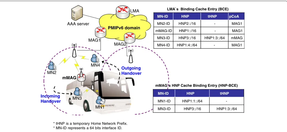
The key idea of the proposed scheme is that the mMAG assigns an MN’s HNP using a sub-prefix of its own HNP when an MN is attached to the mMAG. If the MN initially attaches to the mMAG, the mMAG assigns the HNP to the MN. Otherwise, the mMAG assigns a temporary HNP (tHNP) to the MN. Packets destined for MNs initially attached to the mMAG are delivered to the mMAG based on the mMAG’s HNP through the PMIPv6 tunnel without an additional tunnel header. Meanwhile, packets destined for MNs that moved to the mMAG are also delivered to the mMAG without an additional tunnel header using an IP address swapping mechanism. In the proposed scheme, the mMAG also performs a location update on behalf of the MNs, similar to N-PMIPv6. Therefore, the proposed scheme is able to reduce both the location update cost and the packet tunneling cost.
To support the proposed scheme, some extensions of PMIPv6 are needed as follows:
• Extended binding cache entry (BCE):The LMA maintains a BCE to manage the MNs that are attached to itself. The BCE contains the MN’s ID (MN-ID), MN’s home network prefix (MN_HNP), and proxy care-of address (pCoA, i.e., MAG IP address). To support efficient NEMO, a new field, called a temporary HNP (tHNP), is extended to the BCE, as shown in Fig. 1. The tHNP is designed to enable the delivery of data packets destined for mobile nodes that enter the mobile network from outside without the need for an additional tunnel header. • Home network prefix binding cache entry
(HNP-BCE):To support efficient NEMO, an HNP-BCE is proposed, as shown in Fig. 1. The mMAG maintains the HNP-BCE to manage the MNs’ HNP and MNs’ tHNP. Thus, when an MN attaches to a mMAG, the mMAG creates or updates the HNP-BCE. This HNP-BCE is used for binding updates and packet delivery.
3.1 Initial attachment procedure
PMIPv6 domain
MAG2 MAG1
LMA
AAA server
MN2
MN1 MN3
mMAG
Incoming Handover
MN4
Outgoing Handover
* tHNP is a temporary Home Network Prefix. * MN-ID represents a 64 bits interface ID.
MN-ID HNP tHNP pCoA
MN2-ID HNP2::/16 - MAG1
mMAG-ID HNP1::/16 - MAG1
MN3-ID HNP3::/16 HNP1:3::/64 mMAG
MN4-ID HNP1:4::/64 - MAG1
LMA`s Binding Cache Entry (BCE)
MN-ID HNP tHNP
MN1-ID HNP1:1::/64
-MN3-ID HNP3::/16 HNP1:3::/64
mMAG`s HNP Cache Binding Entry (HNP-BCE)
Fig. 1Network architecture of proposed scheme
LMA, thereby reducing the initial MN attachment costs compared to other existing schemes. This also reduces the size of the BCE in the LMA, as the LMA only man-ages the mMAG’s BCE. When packets destined for MN1 arrive at the LMA, the LMA recognizes these packets as destined for the mMAG. As such, the LMA only appends a single PMIPv6 tunnel header to the packets based on the mMAG’s HNP and sends them to MAG1. Once the packets arrive at MAG1, they are routed to MN1 via the mMAG without any additional tunnel header.
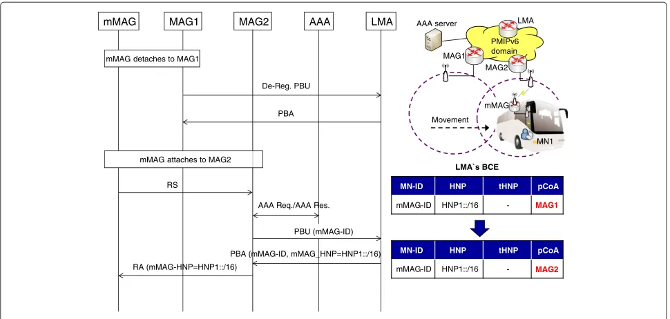
3.2 Network handover procedure
Figure 3 shows the network handover procedure when the mMAG moves to another MAG. When the mMAG moves to the area of MAG2, MAG1 detects the mMAG’s handoff from a layer-2 signal and exchanges PBU/PBA messages with the LMA for de-registration. Once MAG2 detects the mMAG’s movement, it sends a PBU message to the LMA, which then changes the BCE and replies to MAG2 with a PBA message. Unlike the RENEMO scheme, the proposed scheme does not include cached MN-IDs, and
mMAG MAG1 AAA LMA
MN1
RS
RA (mMAG_HNP) mMAG attaches to MAG1
AAA Req./AAA Res. PBU (mMAG-ID)
PBA (mMAG-ID, mMAG_HNP=HNP1::/16)
RS MN1 attaches to mMAG
AAA Req./AAA Res.
RA (MN1_HNP
=HNP1:1::/64)
Bi-directional PMIPv6 tunnel
IP address configuration
IP address configuration
mMAG allocates MN1`s HNP using a sub-prefix of its own HNP
mMAG`s HNP-BCE
MN-ID HNP tHNP
MN1-ID HNP1:1::/64
-MN-ID HNP tHNP pCoA
mMAG-ID HNP1::/16 - MAG1
LMA`s BCE
MAG2 MAG1
MN1 mMAG
LMA AAA server
PMIPv6 domain
MAG1 MAG2 AAA LMA
mMAG attaches to MAG2 mMAG detaches to MAG1
De-Reg. PBU
PBA
LMA`s BCE
MN-ID HNP tHNP pCoA
MN-ID HNP tHNP pCoA
mMAG-ID HNP1::/16
-Fig. 3Network handover procedure of proposed scheme
the MN-HNPs belong to the mMAG in the PBA message. Therefore, the proposed scheme reduces the location update costs when compared with the RENEMO scheme.
3.3 MN handover procedure
The handover of an MN can be classified into two cases: (1) outgoing handover and (2) incoming handover. An outgoing handover occurs when an MN initially attaches to the mMAG and then moves to the area of the MAG (e.g., MN4 in Fig. 1). Meanwhile, an incoming handover occurs when an MN initially attaches to the MAG and then moves to the area of the mMAG (e.g., MN3 in Fig. 1).
3.3.1 Outgoing handover procedure
Figure 4 shows the MN’s outgoing handover procedure. When MN4 moves to the area of MAG1, the mMAG detects MN4’s detachment from a layer-2 signal and sends a de-registration PBU message including MN4’s HNP to the LMA. The LMA creates MN4’s BCE and replies to the mMAG with a PBA message. Upon receiving this PBA message, the mMAG deletes MN4’s HNP-BCE. When MAG1 detects MN4’s movement, it sends a PBU message to the LMA, which then updates the BCE and replies to MAG1 with a PBA message.
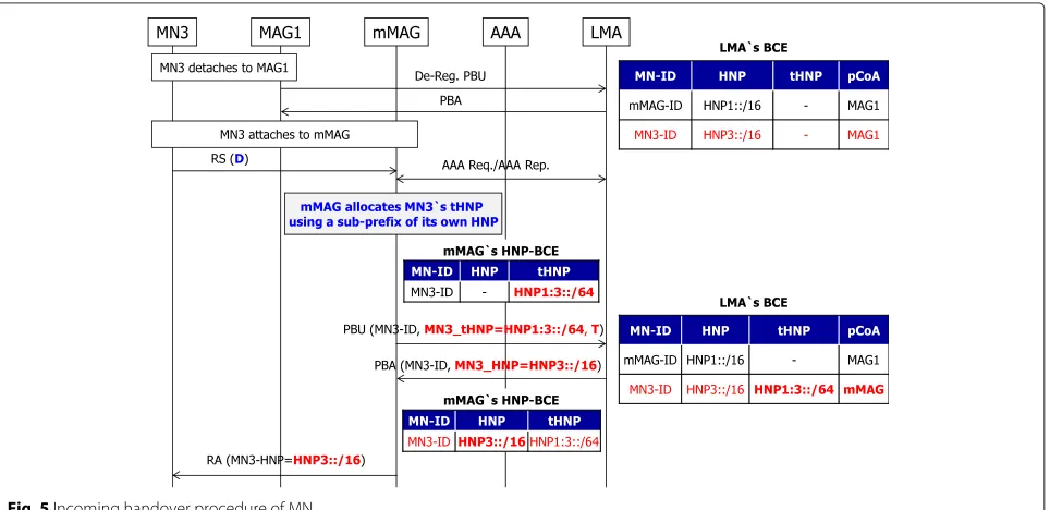
3.3.2 Incoming handover procedure
Figure 5 shows the MN’s incoming handover proce-dure. When MN3 moves to the area of the mMAG, MAG1 detects MN3’s handoff from a layer-2 signal and exchanges PBU/PBA messages with the LMA for de-registration. When attaching to the mMAG, MN3 sends
the mMAG an RS message. The mMAG then checks the ‘D’ flag in the RS message, which is newly defined to iden-tify whether or not MN3 has already completed the initial attachment. The ‘D’ flag is set if the MN has already com-pleted the initial attachment. If the ‘D’ flag is set, the mMAG allocates MN3’s tHNP, instead of an HNP, using a sub-prefix of its own HNP and creates MN3’s HNP-BCE. The mMAG then sends a PBU message including MN3’s tHNP and a ‘T’ flag to the LMA. Here, the ‘T’ flag is extended to the PBU message to indicate that the HNP in the PBU message is a tHNP.
Once the LMA receives the PBU message, it extracts each prefix from the HNP and tHNP of MN3 by mask-ing the mMAG’s subnet prefix and checks whether or not MN3 is connected to the mMAG. If both prefixes extracted from the HNP and tHNP are the same, the LMA decides that MN3 is connected to the mMAG and deletes MN3’s BCE. Otherwise, the LMA decides that MN3 is connected to the MAG and updates the tHNP in MN3’s BCE. In this case, the LMA updates the tHNP in MN3’s BCE, as MN3 is connected to the MAG, and returns a PBA message including MN3’s HNP to the mMAG.
Fig. 4Outgoing handover procedure of MN
in MN3’s HNP-BCE. In this case, the mMAG updates the HNP in MN3’s HNP-BCE, as MN3 is connected to the MAG, and sends an RA message to MN3.
3.4 Data packet delivery procedure
This section describes the data packet delivery procedure in the proposed NEMO support scheme to minimize the packet tunnel header between an MN and the MAG. Pack-ets destined for an MN initially attached to the mMAG (e.g., MN1 in Fig. 1) can be delivered to the mMAG based
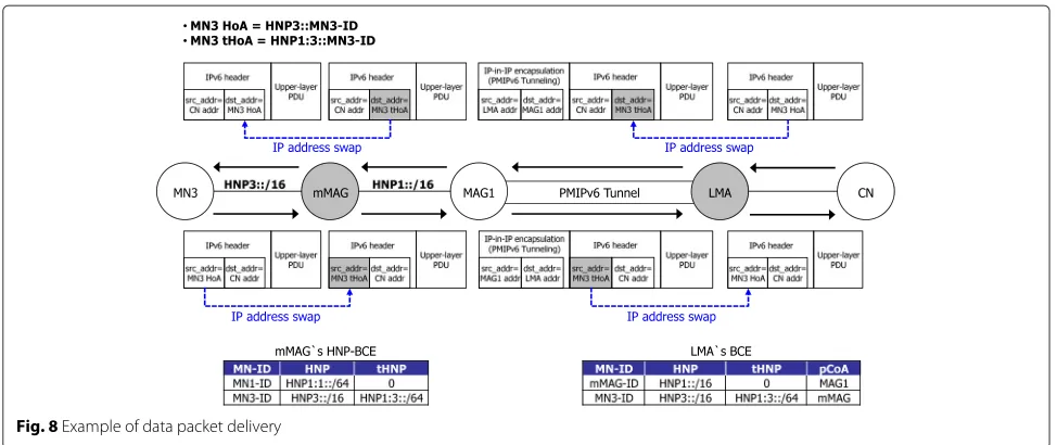
on the mMAG’s HNP without an additional packet tun-nel header because the MN’s HNP is a sub-prefix of the mMAG’s HNP. Yet, packets destined for an MN connected via an incoming handover (e.g., MN3 in Fig. 1) cannot be delivered to the mMAG because the MN’s HNP is not a sub-prefix of the mMAG’s HNP. Therefore, to facilitate the delivery of packets to an MN following an incoming handover without an additional packet tunnel header, a temporary HNP (tHNP) is used, along with an IP address swapping mechanism at the mMAG and LMA. Thus, the
mMAG and LMA have an IP address swapping function that changes either the source address or the destination address in the IP header of the data packet to a tHoA or the HoA.
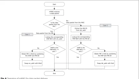
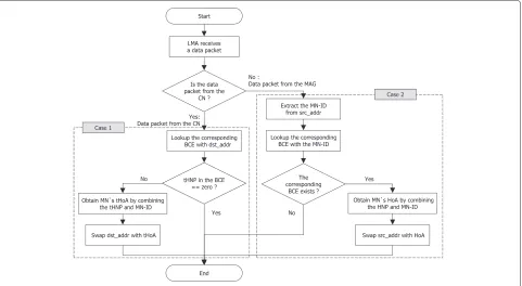
Figure 6 shows the mMAG’s operation for data packet delivery. When the mMAG receives a packet, first it checks the direction of the packet and then processes the packet according to the direction of the packet.
• Case 1: packet from MN at mMAG (1) The mMAG looks up the corresponding
HNP-BCE using the source address (src_addr). (2) If the value of the tHNP in the corresponding
HNP-BCE is zero, the mMAG does not swap the src_addr with a tHoA and sends the data packet to the MAG. Otherwise, the mMAG swaps the src_addr in the IP header of the data packet with a tHoA and sends the data packet to the MAG. The MN’s tHoA is obtained by combining the tHNP and the MN-ID.
• Case 2: packet from MAG at mMAG (1) The mMAG extracts the MN-ID from the
destination address (dst_addr) in the IP header of the data packet. The mMAG then looks up the corresponding HNP-BCE using the MN-ID. (2) If the HNP-BCE corresponding to the MN-ID is
zero, the mMAG does not swap the dst_addr with
the HoA and sends the data packet to the MN. Otherwise, the mMAG swaps the dst_addr in the IP header of the data packet with the HoA and sends the data packet to the MN. The MN’s HoA is obtained by combining the HNP and the MN-ID.
Figure 7 shows the LMA’s operation for data packet delivery. When the LMA receives a data packet, first, it checks the direction of the packet and then processes the packet according to the direction of the packet.
• Case 1: packet from CN at LMA
(1) The LMA looks up the corresponding BCE using the dst_addr.
(2) If the value of the tHNP in the corresponding BCE is zero, the LMA does not swap the dst_addr with a tHoA and tunnels the data packet to the MAG. Otherwise, the LMA swaps the dst_addr in the IP header of the data packet with a tHoA and tunnels the data packet to the MAG. The MN’s tHoA is obtained by combining the tHNP and the MN-ID.
• Case 2: packet from MAG at LMA
(1) The LMA extracts the MN-ID from the src_addr in the IP header of the data packet. The LMA then looks up the corresponding BCE using the MN-ID and decides whether or not to swap the src_addr with the HoA.
Fig. 7Operation of LMA for data packet delivery
(2) If there is no BCE corresponding to the MN-ID, the LMA does not swap the src_addr with the HoA and sends the data packet to the CN. Otherwise, the LMA swaps the src_addr in the IP header of the data packet with the HoA and sends the data packet to the CN. The MN’s HoA is obtained by combining the HNP and the MN-ID.
Figure 8 shows an example of packet delivery for an MN following an incoming handover. Since IP address swap-ping is used, the proposed scheme can deliver a packet to the mMAG without an additional packet tunnel header, except for the PMIPv6 tunnel header.
4 Numerical analysis
In this section, we analyze mathematically the location update cost and the packet tunneling cost to compare the performance between the proposed scheme and existing schemes including rNEMO, N-PMIPv6, and RENEMO. The cost was defined as the product of the message size and hop distance during a measured timeT. In the analy-sis, the router processing cost and initial attachment cost were not considered. To analyze the cost, the following assumptions and notations were used [7].
• The inter-session arrival time was assumed as an exponential distribution with a rate ofλS, and the
average session length was assumed asE(S)in packets.
• The MAG subnet crossing rate was assumed as a general distribution with a mean rate ofμC. • Lx: the size of messagex
• dα−β: the hop distance between network entitiesα andβ
• LUα−β(=dα−β·(LPBU+LPBA)): the unit cost of the PBU/PBA messages betweenαandβ
• RSα−β(=dα−β·LRS): the unit cost of the RS messages betweenαandβ
• RAα−β (=dα−β·LRA): the unit cost of the RA messages betweenαandβ
• AAAα−β (=dα−β·LAAA): the unit cost of the AAA messages betweenαandβ
In the rNEMO scheme, when a mobile network moves to another MAG, the MAG performs a location update operation with the LMA by sending/receiving a PBU/PBA message for each MN within the mobile network. Plus, each MN exchanges RS/RA messages with the MAG. The average number of subnet crossings duringT is equal to
μC ·T. Therefore, the location update cost (CLU) of the
rNEMO scheme can be represented by
CrNEMOLU = μC·T·δ(τ·RSMN−MAG+τ·RAMAG−MN
Fig. 8Example of data packet delivery
whereδis the number of MNs, andkandτdenote the unit transmission costs in a wired and wireless link, respec-tively. Generally, since the transmission cost for a wireless link is larger than that for a wired link,τ is larger thank.
The packet tunneling cost denotes the size of the IP tun-nel header of the data packets delivered from the CN to an MN. In the case of rNEMO, no tunnel header is used, except for the PMIPv6 tunnel header, between the MAG and the LMA. The number of packets delivered duringT is represented byλS·T·E(S). Therefore, the packet tunnel-ing cost (CPT) for the rNEMO scheme can be represented
by
CPTrNEMO=δ·λS·T·E(S)(k·dLMA−MAG·LT) (2)
whereLTis the length of the tunnel header.
In the N-PMIPv6 scheme, when the mMAG moves to another MAG, only the mMAG performs a location update operation on behalf of all the MNs. Therefore, the location update cost (CLU) of the N-PMIPv6 scheme can
be calculated by
CLUN−PMIPv6 = μC·T(τ·RSmMAG−MAG+τ·RAMAG−mMAG
+k·AAAMAG−AAA+2k·LUMAG−LMA). (3)
In the N-PMIPv6 scheme, once the LMA receives pack-ets sent by the CN, it makes two tunnel headers based on recursive look-ups. Therefore, the packet tunneling cost (CPT) for the N-PMIPv6 scheme can be expressed by
CNPT−PMIPv6=δ·λS·T·E(S)(k·dLMA−MAG·2·LT +τ·dMAG−mMAG·LT).
(4)
In the RENEMO scheme, the mMAG also performs a location update on behalf of all the MNs. Yet, the PBA
message includes all the MN-ID and HNP options accord-ing to the number of MNs connected to the mMAG. Thus, when adding the length of the MN-ID and MN-HNP options according to the number of MNs, the location update cost (CLU) of RENEMO can be derived by
CLURENEMO=μC·T(τ·RSmMAG−MAG+τ·RAMAG−mMAG
+k·AAAMAG−AAA+2k·LUMAG−LMA
+δ·k·dLMA−MAG·(LMN−ID+LMN−HNP)).
(5)
In the RENEMO scheme, the packet tunneling cost is the same as that for rNEMO, as no tunneling is employed, except for the PMIPv6 tunnel header, between the MAG and the LMA. Therefore, it can be expressed by
CPTRENEMO=δ·λS·T·E(S)(k·dLMA−MAG·LT). (6)
In the proposed scheme, when the mMAG moves to another MAG, the mMAG performs a location update operation on behalf of all the MNs. Therefore, the loca-tion update cost (CLU) of the proposed scheme can be
represented by
CProposedLU = μC·T(τ·RSmMAG−MAG+τ·RAMAG−mMAG
+k·AAAMAG−AAA+2k·LUMAG−LMA). (7)
In the proposed scheme, no tunnel header is used, except for the PMIPv6 tunnel header, between the MAG and the LMA, similar to rNEMO and RENEMO. There-fore, the packet tunneling cost (CPT) for the proposed
scheme can be represented by
CPTProposed=δ·λS·T·E(S)(k·dLMA−MAG·LT). (8)
Table 1Parameters for numerical results
and LPBU/LPBA/LT were 112/96/40 bytes, respectively. The option message size of the MN-ID and MN-HNP for RENEMO were 20 and 32 bytes, respectively.
Figure 9 shows the total cost according to the num-ber of MNs. The total cost was the sum of the location update cost and packet tunneling cost. In this figure, the total cost for rNEMO was much higher than that for the other schemes, since the individual location update cost impacted the total cost when increasing the number of MNs. When compared with RENEMO, the proposed scheme reduced the total cost by about 33–42 % when increasingδfrom 10 to 20. This was due to the increased PBA message size in RENEMO when increasing the num-ber of MNs.
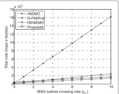
Figure 10 shows the total cost according to the MAG subnet crossing rate. When μC was 10, the proposed scheme reduced the total cost by about 18 % when com-pared with N-PMIPv6 due to a lower packet tunneling cost.
otal cost (hops x kb
ytes)
Figure 11 also shows that the total cost of the proposed scheme was lower than that of the other schemes when increasing the session arrival rate. When λSwas 10, the proposed scheme reduced the total cost by about 17 % when compared with RENEMO. Therefore, we have con-firmed that the proposed scheme outperformed rNEMO, N-PMIPv6, and RENEMO in terms of the total cost.
5 Simulation results
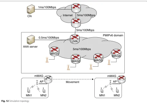
This section presents the simulation results for the per-formance evaluation using an NS-2 simulator [24]. The network topology and node configuration of the simula-tion are shown in Fig. 12, and the simulasimula-tion parameters are summarized in Table 2. The proposed scheme was compared with the existing schemes including rNEMO, N-PMIPv6, and RENEMO in terms of the inter-MAG
CN
AP
MN1 MN2
mMAG
1ms/100Mbps
5ms/100Mbps
0.5ms/100Mbps
AAA server
Internet
5ms/100Mbps
AP
MN1 MN2
mMAG
Movement
5ms/100Mbps LMA
MAG2 MAG3
MAG1
MAG4 PMIPv6 domain
Fig. 12Simulation topology
handover latency, UDP throughput, and signaling over-head. In the simulation, MN1 and MN2 were attached to the mMAG and communicated with the CN at a fixed location, respectively, while the mMAG moved from MAG1 to MAG4 at a velocity of 10 m/s during a service session with the CN. The mMAG performed an inter-MAG handover at 40, 80, and 120 s. The MNs used a real-time stream service with CBR traffic on the UDP transport protocol, and each MAG had an IEEE 802.11b interface with 250-m coverage.
Table 2Parameters for simulation
Parameters Values
Coverage radius 250 m
Distance between MAGs 400 m
MAC protocol IEEE 802.11b
UDP traffic (packet interval) CBR (0.005 s)
UDP packet size 512 bytes
Movement speed 36 km/h (10 m/s)
Inter-MAG handover time 40, 80, 120 s
Simulation duration 160 s
Figure 13 shows the inter-MAG handover latency of MN1 when the mMAG moved between the MAGs. In this figure, the proposed NEMO scheme and N-PMIPv6 had a lower handover latency than the other schemes. This was because the mMAG in N-PMIPv6 and the proposed scheme performed an inter-MAG handover on behalf
rNEMO N-PMIPv6 RENEMO Proposed 0
5 10 15 20 25 30 35 40 45 50
Inter-MA
G
hando
v
er latency (ms)
of all the MNs. Whereas, in the rNEMO scheme, each MN performed an inter-MAG handover by exchanging PBU/PBA messages with the LMA. Therefore, rNEMO had the longest handover latency among the four schemes. This figure also shows that RENEMO had a slightly longer handover latency than N-PMIPv6 and the pro-posed scheme. Although the mMAG in RENEMO also performed an inter-MAG handover on behalf of all the MNs, the stored MN-IDs and MN-HNPs belonging to the mMAG were all contained in the PBA message, which increased the PBA message size. When the PBA mes-sage was delivered from the MAG to the mMAG, some delay was also incurred with the wireless link due to the increased PBA message size.
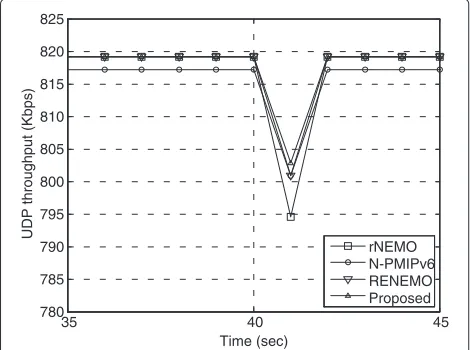
Figure 14 shows the UDP throughput of MN1 when the mMAG moved from MAG1 to MAG2. In this figure, the UDP throughput for all schemes was degraded at about 40 s due to an inter-MAG handover latency, dur-ing which UDP packets could not be delivered due to service disruption. N-PMIPv6 had a lower UDP through-put than the other schemes. In the case of N-PMIPv6, the data packets were delivered through two nested tun-nel between the LMA and the mMAG. When the packets with the additional tunnel header were delivered through a wireless link between the MAG and mMAG, the addi-tional tunneling overhead decreased the UDP throughput. This figure also shows that rNEMO had the lowest UDP throughput of about 40 s. This was because rNEMO had the highest inter-MAG handover latency, which decreased the UDP throughput during an inter-MAG handover.
Figure 15 shows the signaling overhead of the exist-ing schemes and the proposed scheme. The signalexist-ing overhead was the sum of the signaling packets generated during the simulation time. In this figure, rNEMO had
35 40 45
Fig. 14Comparison of UDP throughput
rNEMO N-PMIPv6 RENEMO Proposed 0
Sum of signaling pac
k
ets siz
e (b
ytes)
Fig. 15Comparison of signaling overhead
the highest signaling overhead, as the MAG performed a location update for each MN whenever the mobile net-work moved to another MAG. In the case of RENEMO, the LMA delivered the stored MN-IDs and MN-HNPs belonging to the mMAG to the new MAG through an extended PBA message during the handover. Therefore, this extended PBA message slightly increased the sig-naling overhead. The proposed scheme had the lowest signaling overhead as the mMAG in the proposed scheme did not need to exchange PBU and PBA messages with the LMA for initially attached MNs.
Therefore, the simulation results confirmed that the proposed scheme outperformed the existing schemes, such as rNEMO, N-PMIPv6, and RENEMO.
6 Conclusions
Competing interests
The authors declare that they have no competing interests.
Acknowledgements
This research was supported by the National Research Foundation of Korea (NRF) grant funded by the Korea government (MSIP)
(NRF-2013R1A1A4A01012534) and the IT R&D program of MSIP/IITP [10041145, Self-Organized Software platform (SoSp) for Welfare Devices]. (COMOESTAS: Continuous Monitoring of Medication Overuse Headache in Europe and Latin America: Development and Standardization of an Alert and Decision Support System).
Author details
1School of Electronics Engineering, Kyungpook National University, Daegu, Korea.2Department of Military Electronic Communication, Yeungjin College, Daegu, Korea.
Received: 13 May 2015 Accepted: 21 August 2015
References
1. Z Zhang, X Chai, K Long, AV Vasilakos, L Hanzo, Full duplex techniques for 5G networks: self-interference cancellation, protocol design, and relay selection. IEEE Commun. Mag.53(5), 128–137 (2015)
2. M Reza Rahimi, N Venkatasubramanian, S Mehrotra, AV Vasilakos, in Proceedings of IEEE UCC. MAPCloud: mobile applications on an elastic and scalable 2-tier cloud architecture (Chicago, 2012), pp. 83–90
3. M Youssef, M Ibrahim, M Abdelatif, L Chen, AV Vasilakos, Routing metrics of cognitive radio networks: a survey. IEEE Communications Surveys and Tutorials.16(1), 92–109 (2014)
4. Y Zeng, K Xiang, D Li, AV Vasilakos, Directional routing and scheduling for green vehicular delay tolerant networks. Wireless Networks.19(2), 161–173 (2012)
5. T Ernst, The information technology era of the vehicular industry. ACM SIGCOMM Comput. Commun. Rev.36(2), 49–52 (2006)
6. S Pack, X Shen, JW Mark, J Pan, Mobility management in mobile hotspots with heterogeneous multihop wireless links. IEEE Commun. Mag.45(9), 106–112 (2007)
7. S Pack, T Kwon, E Paik, An adaptive network mobility support protocol in hierarchical mobile IPv6 networks. IEEE Trans. Veh. Technol.58(7), 3627–3639 (2009)
8. T Ernst, H Lach, Network mobility support terminology. IETF RFC 4885 (2007)
9. V Devarapalli, R Wakikawa, A Petrescu, P Thubert, Network mobility (NEMO) basic support protocol. IETF RFC 3963 (2005)
10. D Johnson, C Perkins, J Arkko, Mobility support in IPv6. IETF RFC 3775 (2004)
11. S Gundavelli, K Leung, V Devarapalli, K Chowdhury, B Patil, Proxy Mobile IPv6. IETF RFC 5213 (2008)
12. S Pack, inProceedings of IEEE CCNC. Relay-based network mobility support in proxy mobile IPv6 networks (Las Vegas, 2008), pp. 227–228
13. J-H Lee, T Ernst, Lightweight network mobility within PMIPv6 for transportation systems. IEEE Syst. J.5(3), 352–361 (2011)
14. J-H Lee, T Ernst, N Chilamkurti, Performance analysis of PMIPv6-based network mobility for intelligent transportation systems. IEEE Trans. Veh. Technol.61(1), 74–85 (2012)
15. S Ryu, J-W Choi, K-J Park, Performance evaluation of improved fast PMIPv6-based network mobility for intelligent transportation systems. J. Commun. Netw.15(2), 142–152 (2013)
16. I Soto, CJ Bernardos, M Calderon, A Banchs, A Azcorra, Nemo-enabled localized mobility support for internet access in automotive scenarios. IEEE Commun. Mag.47(5), 152–159 (2009)
17. S Jeon, R Aguiar, B Sarikaya, Network mobility support using mobile MAG in Proxy Mobile IPv6 domain. IETF draft-sijeon-netext-mmag-pmip-00 (2012)
18. H-B Lee, Y-H Han, S-G Min, Network mobility support scheme on PMIPv6 networks. Int. J. Comput. Net. Commun. (IJCNC).2(5), 206–213 (2010) 19. S Jeon, Y Kim, Cost-efficient network mobility scheme over proxy mobile
IPv6 network. IET Commun.5(18), 2656–2661 (2011)
20. Z Yan, H Zhou, I You, N-NEMO: a comprehensive network mobility solution in Proxy Mobile IPv6 network. J. Wirel. Mob. Netw. Ubiquit. Comput. Dependable Appl.1(2/3), 52–70 (2010)
21. T Arita, F Teraoka, PNEMO: a network-based localized mobility management protocol for mobile networks. Inf. Media Technol.7(2), 861–871 (2012)
22. S Jeon, N Kang, Y Kim, Resource-efficient network mobility support in Proxy Mobile IPv6 domain. Int. J. Electron. Commun.66(5), 390–394 (2012) 23. B Mohammed, I Mahamod, N Rosdiadee, AB Zain, Proxy Mobile IPv6
handover management in vehicular networks: state of the art, taxonomy and directions for future research. Wirel. Pers. Commun.84(2), 1509–1534 (2015)
24. NS-2. http://www.isi.edu/nsnam/ns, Accessed 28 August 2015
Submit your manuscript to a
journal and benefi t from:
7Convenient online submission 7Rigorous peer review
7Immediate publication on acceptance 7Open access: articles freely available online 7High visibility within the fi eld
7Retaining the copyright to your article