R E S E A R C H
Open Access
New delay-efficient TDMA-based distributed
schedule in wireless mesh networks
Jae-Hyun Kim
*, Jae-Ryong Cha and Han-Joon Park
Abstract
Time division multiple access (TDMA)-based medium access control (MAC) protocols can guarantee quality of service (QoS) in wireless environments. However, in an environment where multihop packet transmissions are necessary for real-time communications, each node may experience the well-known queuing delay. This queuing delay increases multihop packet transmission delay, resulting in not meeting the delay bound of real-time applications in multihop wireless networks. This article first introduces two kinds of queuing delays that can occur in multihop wireless networks. Then, this article proposes a new delay-efficient TDMA-based distributed scheduling scheme to eliminate the secondary queuing delay. For the performance analysis of the proposed scheme, the scheduling overhead is first evaluated in terms of power consumption. Next, the multihop packet transmission delay of the proposed scheduling scheme is derived and validated through a simulation, before comparing the result with that of the conventional minimum length scheduling scheme which employs distance-2 graph coloring. According to the simulation and analysis results, for a deterministic packet arrival, the proposed scheme works well irrespective of the packet interarrival rate and outperforms the conventional graph coloring. However, in case of a non-deterministic packet arrival, the multihop packet transmission delay of the proposed scheme is slightly higher than that of the
conventional graph coloring because the probability that each node has more than two packets increases at the beginning of the frame. However, the multihop packet transmission delay of the conventional graph coloring is intolerable when the packet interarrival rate is high.
Keywords: TDMA, Scheduling, Quality of service, Realtime services, Allocation order
1 Introduction
Wireless mesh networks (WMNs) are emerging commu-nication networks consisting of nodes that automatically establish an ad-hoc network and maintain mesh connec-tivity. Because of their advantages over other wireless networks, WMNs are progressing rapidly and are inspir-ing numerous applications in commercial and tactical environments. With the popularity of WMNs, support-ing quality of service (QoS) over multihop radio links is becoming an issue because multihop packet transmission delay increases quickly with the increase in the num-ber of hops [1]. Previous studies on WMNs have mostly been studied based on 802.11 wireless local area networks (WLANs). One of the major drawbacks of such networks is that it is difficult for them to support QoS, which is
*Correspondence: [email protected]
Won-Cheon Hall 208, San5 Wonchun-Dong, Suwon, Korea
essential for supporting real-time applications, particu-larly in multihop wireless networks. This is because packet transmission delay is accumulated at each hop on a path. Meanwhile, scheduling schemes based on time division multiple access (TDMA) have been proposed for WMNs. Most TDMA scheduling schemes [2-13] for WMNs have been proposed for determining the minimum length schedules. However, although such schemes reduce the frame length, they may bring about queuing delay, which can increase the multihop packet transmission delay in WMNs.
Recently, TDMA-based QoS-aware scheduling schemes [14-19] have been proposed for supporting various appli-cations such as voice and video calls in WMNs. However, these schemes necessarily need a centralized base station for achieving their goals, such as a minimum length sched-ule considering the scheduling delay, delay-constrained schedule of flows, and link activation schedule to bound end-to-end delay [1]. Brief descriptions of these schemes
are presented in the following section. Therefore, this article proposes a new delay efficient TDMA-based dis-tributed scheduling scheme for eliminating secondary queuing delay, which is defined in subsequent sections, and for ultimately reducing the multihop packet transmis-sion delay in WMNs.
2 Related study
This section introduces conventional studies related to the TDMA-based QoS-aware scheduling scheme. Recently, various TDMA-based QoS aware-scheduling schemes have been introduced for WMNs [1].
In [14], the authors schedule different types of flows for satisfying bandwidth and delay requirements. In the first phase, the algorithm attempts to allocate interference-free slots (using multiple channels) to a flow based on the max-imum bandwidth requirement of the flow. The second phase is invoked for a flow if the first phase fails to allocate sufficient slots to satisfy even the minimum bandwidth requirement.
In the mechanism proposed in [15], first, a given net-work is transformed into a conflict graph whose vertices represent links and there is an edge between two vertices if two links conflict (interfere) with each other. Determin-ing the order of transmission, in such a conflict graph, for a conflict-free TDMA schedule with minimum scheduling delay is NP-complete. Therefore, the authors formulate this problem as a linear programming optimization prob-lem. Given the minimum scheduling interval and relative activation times, the authors show how to determine the minimum length TDMA schedule (actual assignment of links to slots) in polynomial time.
To prevent computational complexity of the optimum solution, the authors in [16] have proposed a ‘bottleneck first scheduling’(BFS) scheme, where scheduling decisions at stations having higher traffic loads are made before those having lower traffic loads. At each station, schedul-ing decisions for constant bit rate (CBR) packets with more hops to their destinations are made first. Through simulations, the authors show that the delay of BFS is bet-ter than ‘earlier deadline first’ (EDF) and ‘first come first serve’ (FCFS) scheduling.
In the mechanism proposed in [17], the nodes (and thus links) in the network are first labeled either even or odd (two-slot scheduling). Then, while determining paths, only those paths that go through nodes having alter-nate labeling are considered. Using sub-channelization of OFDMA, secondary interference between two links in the same slot is prevented by assigning different channels to the links. Once the slot requirements and routing paths are determined, each node employs a local (wireline-type) scheduling policy. The scheduling policy determines the order in which packets leave the buffer at each node, and the authors show that such a mechanism provides
two-approximation bounds for the end-to-end delay. The problem of finding feasible routes (to and from gateway to network nodes) in an even-odd labeled (tree) network is formulated as a linear program and heuristics using Dijkstra’s shortest path algorithm have been proposed.
The authors of [18] have proposed a ‘load-balanced weighted shortest path with a retry’ routing heuristic. In this heuristic, first, the shortest-hop algorithm is used to determine a path. If one or more edges on the path are blocked, those are removed from the graph and the heuristic is applied again to find a suitable path. Next, a call admission control (CAC) algorithm is applied which considers the unsolicited grant service/real-time polling service in WiMAX. To manage the jitter value of a con-nection, the path from a source node to a destination node is partitioned into two segments;one segment is from the source to the penultimate node (the node just before the destination), and the other segment is the link between the penultimate node and the destination. The delay require-ment is that the total delay on both the segrequire-ments should be less than the delay constraint. Because of the split, to ensure the jitter constraint of the path, the scheduler only needs to look at the second segment between penultimate node and destination. This is achieved by fixing an offset value and scheduling the packets within the limit of the jitter grant interval.
In [19], an online algorithm that works in three phases has been proposed. In the first phase, the algorithm con-structs an auxiliary graph from the given topology graph. A vertex in the auxiliary graph is a four-parameter tuple of the form (node, slot, channel, hop). An edge is formed between two vertices if a set of rules is satisfied. The rules model the interference and delay constraints. In the second phase, Dijkstra’s shortest path algorithm is run to output the delay-constrained schedule while finding a routing path, assigning a channel, and scheduling links in the process. In the third phase, an unfavorable schedule is filtered to incorporate an arbitrary interference graph. The authors compare this algorithm with an offline opti-mal solution and show that it accepts around 90% of the calls with respect to the optimal solution.
3 System model
4 Queuing delay in multihop wireless networks
In this section, we describe two main factors that cause an increase in the multihop packet transmission delay in multihop wireless networks. In previous studies [2-13], TDMA scheduling is generally used to determine the min-imum length schedules. However, such schedules may cause additional queuing delays, which have a negative influence on delay-sensitive networks. The QoS of real-time applications in multihop wireless networks may not be guaranteed if additional queuing delays occur.
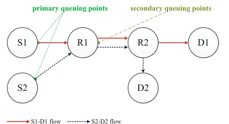
Figure 1 shows a simple multihop wireless network in which queuing delay occurs. In single-hop wireless net-works, queuing delay occurs when the packet arrival rate in a source node is higher than the packet transmis-sion (service) rate. In this article, such a queuing delay is referred to as the primary queuing delay and primary queuing points (QPs) in Figure 1 represent the examples of such a case. On the other hand, in multihop wireless networks, an additional queuing delay may occur, which is referred to as the secondary queuing delay in this article. The secondary queuing delay occurs when multiple flows pass through an outbound link of a relay node. The sec-ondary QP shown in Figure 1 represents the point where the secondary queuing delay occurs.
For example, in Figure 1, multiple flows pass through the Node R1-to-R2 link. These flows share a slot for trans-ferring packets. Assume that the network employs the minimum length schedule. Then, Node R1 allocates only one slot for transferring packets to node R2. It is also assumed that Node S1 and Node S2 are supposed to send a packet to Node R1 in the 1stslot and the 2ndslot, respec-tively. Moreover, Node R1 is scheduled to send a packet to Node R2 in the 3rdslot. It is also assumed that, in each
node, the arrival of a packet from application layer is con-current with the start of a frame. In the 3rd slot in the frame, Node R1 has two packets to send:one from Node S1 and another from Node S2. However, Node R1 can trans-fer the packet received from node S1 in the current frame and can transfer the packet received from Node S2 in the
Figure 1Queuing points (QPs) in multihop wireless networks.
next frame because it can transfer only one packet per link in a frame as prescribed by the minimum length schedule. In conclusion, the minimum length schedule may work well in single-hop wireless networks with high throughput and short delay. However, in multihop wireless networks, it may cause secondary queuing delay because only one common slot is allocated for multiple flows.
Therefore, this article proposes a new distributed scheduling scheme to eliminate the secondary queuing delay, thereby ultimately reducing the multihop packet transmission delay.
5 Proposed scheduling scheme
In this section, the operational procedures for the pro-posed scheduling scheme are described in detail. The operational procedures are classified into two phases: Phase I and Phase II. In Phase I, each node obtains paths using the ad-hoc on-demand distance vector (AODV) routing protocol [20] and gathers the information on its one-hop neighbors. These two tasks are also performed in the conventional schemes [9,21] prior to the TDMA scheduling, although both the routing algorithms and the approaches for obtaining the neighbor information are slightly different. Moreover, these tasks are generally excluded during the overhead analysis in the conventional tasks, as these tasks are considered as input parameters for scheduling. Therefore, we also exclude Phase I during the overhead analysis for performance comparison with the conventional schemes. However, we have performed these tasks during the simulation.
On the other hand, Phase II involves three steps for slot allocation: an initial frame length synchronization (IFLS) process, a multihop slot allocation (MSA) pro-cess, and a global frame length synchronization (GFLS). First, IFLS determines the initial frame lengthLinit, which
can be used initially for slot allocation in the network. Second, the MSA process allocates a different slot to each flow in a link to eliminate the secondary queuing delay. For example, in Figure 1, two flows exist between Node R1 and Node R2. Therefore, the proposed scheme allocates two different slots for two flows in the Node R1-to-R2 link. Although such a slot allocation can elim-inate the secondary queuing delay, it results in a large frame length. In such a case, it is important to consider the order of the slots allocated on a path. Therefore, we show the delay effect by an allocation order as well as demonstrate the manner in which slots should be allo-cated sequentially in a flow after the routing path is established.
frame length, which can be used globally in the network. After all three processes are completed, all the nodes in the network transfer packets in their allocated slots. This article describes the details of Phase II from the following section onward. The description of two tasks performed in Phase I is not included, because it is beyond the scope of this article as mentioned before.
5.1 Initial frame length synchronization: IFLS
From this section onward, the three steps of Phase II are described in detail. First, for TDMA scheduling, it is necessary to determine the initial frame length, which can be used commonly throughout the TDMA network. In [21], the authors assume that the initial frame length is sufficiently large for the allocation of slots to all the nodes. However, all the nodes carrying out the proposed MSA process must exchange a frame map with each other, where the frame map represents the bit-wise expression of the slot allocation status. A detailed description is pro-vided in the following section. Thus, our assuming too large frame length results in the large overhead in the proposed scheme. Therefore, in this study, each node obtains information on the initial frame length by broad-casting hop information. In order to obtain the initial frame lengthLinit, each node gathers the hop information
by broadcastingh(i).h(i)indicates the hop information to the destination, which a source node i obtains after the completion of routing. When a node hears h(i) , if the received hop value is higher than the one it currently knows, it rebroadcasts the new value. After some prede-termined dissemination time, all nodes obtains the highest hop value (hmax) fromh(i). In the proposed MSA process,
each node allocates a different slot to each flow in a link. Therefore, under the condition that each node manages
only one flow, the upper bound of the initial frame length can be determined by
Linit=hmax·N, (1)
where N is the total number of nodes in the network. Once initial frame length synchronization is completed, then each node carries out the MSA process using the same initial frame lengthLinit.
5.2 Multihop slot allocation: MSA
In this section, we describe the proposed MSA process in detail. First, we assume that each node follows global slot synchronization. Thus, all nodes know the starting time of each frame. Before the description of the proposed MSA process, we first introduce the delay effect caused by an allocation sequence of TDMA slots and show that the allocation sequence in a flow is critical for reducing the multihop packet transmission delay in an environment where a node allocates a different slot to each flow in a link.
5.2.1 Delay effect produced by an allocation sequence
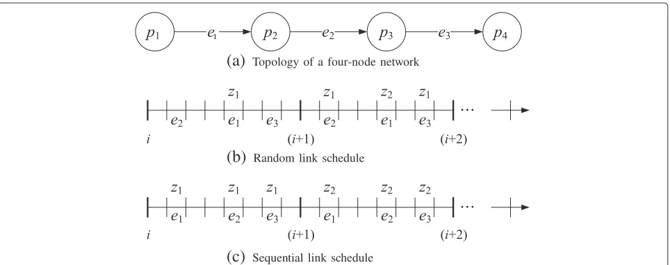
In this study, the MSA process allocates a different slot to each flow in a link in order to eliminate the secondary queuing delay. In such a slot allocation, we must consider the sequence of the slots allocated. Figure 2 shows the delay effect produced by the allocation sequence of the TDMA slots on a path. In Figure 2, the number of nodes, q, is 4 and the number of hops,h, is 3.hrepresents the distance between a source node and a destination node. It is assumed that the source nodep1is supposed to
trans-fer a packetz1from theith frame. If the slot allocation is
randomly carried out(e2e1e3) , the destination,p4 , will
(a)
Topology of a four-node network(b)
Random link schedule(c)
Sequential link schedulereceivez1in the(i+1)th frame (Figure 2b). In this article,
such a link schedule is referred to as a random link sched-ule. However, as shown in Figure 2c,z1will be transferred
top4in theith frame because the slots on the path are
allo-cated(e1e2e3)sequentially. Such a link schedule is referred
to as a sequential link schedule in this article. Therefore, if the sequential link schedule is not considered, the mul-tihop packet transmission delay may be quite large as the number of hops increases.
Now, we derive the multihop packet transmission delay caused by a random link schedule. We assume that the traffic flow between all the node pairs in the network is uniform and that the processes of new packet arrival at the different nodes are independent. Therefore, we now concentrate on the characteristics of one node, and thus, it is assumed that the node transmits a packet in the first slot of each frame. Consider a typical packet generated by a node. Because we assume the stop-and-go queuing system [23], the total packet transmission delay suffered by a packet, Dr , can be obtained by using the follow-ing three components (Figure 3): (1) the time between its generation and the end of the current frame; (2) the aver-age frame delay, which indicates the number of frames required to transfer a packet from the source to the desti-nation; and (3) the time between the start of the last frame and its reception at the destination. Given that all the frames are of equal length, the average time between the packet generation time and the end of the current frame is 0.5TM , where TM is the frame length. Next, assum-ing that the slot for the destination is randomly allocated in a frame, we observe that the time between the start of the last frame and packet reception at the destination is 0.5TM+T. Finally, the average frame delayFh(h≥2)can be calculated as
Fh=
h+1
k=3 k
/h!=
h+1 2
. (2)
Proof.Now, we prove the above equation. It is assumed that a node is supposed to transfer z1 from the ith
frame in Figure 2. If the slot allocation is completed
randomly and h=3, then cases exists as many as
3!. For each case, the frame delay is TM (e1e2e3),
2TM (e1e3e2,e2e1e3,e2e3e1,e3e1e2) , and 3TM (e3e2e1)
long. Thus, F3 is 12TM/3!= 2TM. If we consider each h(≥2), we obtain
F2=3TM/2! ,F3=12TM/3! ,F4=60TM/4! ,. . ..
Accordingly, the total multihop packet transmission delay suffered by a packet,Dr, is given by
Dr = 0.5TM+(Fh−1)TM+0.5TM+T (3) = FhTM+T.
Figure 4 shows the frame delay (number of frames) with an increase in the number of hops. In Figure 4, Lower boundandUpper boundindicate that the links are scheduled sequentially in the order ofe1 →e2→ · · · → eh and eh → eh−1 → · · · → e1, respectively. From
this result, it can be found that the allocation sequence of the TDMA slots on a path may be an important fac-tor in multihop wireless networks if the delay bound must be considered. Therefore, the objective of this study is to sequentially allocate the slots, such that the allocated link sequence becomes e1 → e2 → · · · → eh on a path within one frame, resulting in reducing the multihop packet transmission delay.
5.2.2 MSA process
To efficiently describe the proposed MSA process, we show two types of examples using an algorithm and a figure. To carry out the proposed MSA process, three packets are used: a map request (MAPREQ) packet, a map
response (MAPREP) packet, and a slot allocation (SA)
packet. The MAPREQ and MAPREP packets are used by
a node to request the frame map of its neighbors and to respond to the request, respectively. The SA packet is employed for transferring the information on the allo-cated slot index to the next node. The followings are some terminologies used for describing the proposed MSA pro-cess.
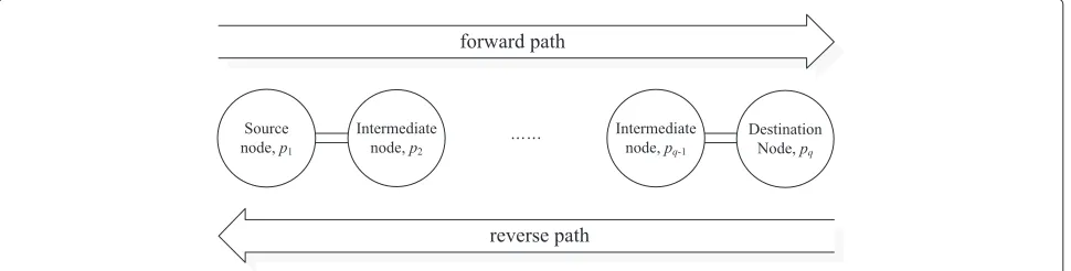
• forward/reverse path: path to the destination/source node.
Figure 4Delay effect by an allocation sequence.
• TN/RN: a transmitting node and a corresponding receiving node in an allocated slot.
• Allocated Slot Index: the slot index allocated. • next node: a neighbor peer node to the destination
node in a forward path.
• MACNEXT: medium access control (MAC) address of a next node.
• MACSOURCE: MAC address of a source node. • MACDESTINATION: MAC address of a destination
node.
Some of the above terms are shown with regard to for-ward and reverse paths in Figure 5. During the proposed MSA process, all the nodes related to a flow (except the destination node) always have two tasks to perform. One is to obtain frame maps from all their one-hop neigh-bors, and the other is to transfer an SA packet to the next node on the path after allocating the slot(s) on the basis of the obtained frame maps. Each node knows which node it transfers the SA packet because the routing pro-cess has already been completed in Phase I. A MAPREQ
Table 1 Field size of packets used for the proposed MSA process
Fields Size (bits)
MAPREQID 8
MAPREPID 8
SA ID 8
MACNEXT 48
Allocated Slot Index 16
packet includes the forwarding information on an identi-fication (ID) field, a MAPREPpacket on an ID field and a
frame map field, and an SA packet on the MACNEXTfield
and theAllocated Slot Indexfield. Table 1 lists the size of each field. The field size for an ID and an address is based on the values in [20]. As explained before, a frame map represents the bitwise expression of the slot allocation sta-tus in a node. The length of the frame map is equal to the frame lengthLinit. Initially, the frame maps of all the
nodes are set as zeros. During the proposed MSA process, a node sets the part allocated as TN or RN in its frame map to ‘1’. A node’s frame map is updated each time a node receives an SA packet. If a source node is ready for the slot allocation in a flow, then it unicasts the SA packet after allocating the slot(s) on the basis of the obtained frame maps.
Algorithm 1 shows the proposed MSA process initiated by a source node. Further, Algorithm 2 shows the pro-posed MSA process when either an intermediate node or a destination node receives an SA packet from node pk (1 ≤ k < q,q ≥ 2)in a forward path. An intermediate node or a destination node invokes Algorithm 2 when-ever it receives an SA packet wherein MACNEXTis equal
to its MAC address. In Algorithm 2, when an intermedi-ate node allocintermedi-ates the slot(s) as a TN, it is very important for the intermediate node to reserve the right-hand side slot for comparison with theAllocated Slot Indexwithin the SA packet received, such that multihop links can be scheduled sequentially on a path.
Algorithm 1. MSA in a source node
1: ifk=1then
2: p1first obtains frame maps of its one-hop neighbors by exchanging MAPREQand MAPREP
packets.
3: p1allocates the commonly available slot(s) for bothp1andp2as a TN.
4: p1transfers the SA packet with Allocated Slot Index top2. 5: end if
Algorithm 2. MSA in an intermediate/a destination node
1: if1<k<qthen
2: Based on the receivedAllocated Slot Index,pk allocates the slot(s) for bothpk−1andpkas an
RN.
3: Then,pkobtains the frame map of its one-hop neighbors by exchanging MAPREQand MAPREP
packets.
4: pkallocates the commonly available slot(s) for bothpkandpk+1as a TN.
5: pktransfers the SA packet with Allocated Slot Index topk+1. 6: else ifk=qthen
7: Based on the receivedAllocated Slot Index,pq allocates the slot(s) for bothpq−1andpqas an
RN. 8: end if
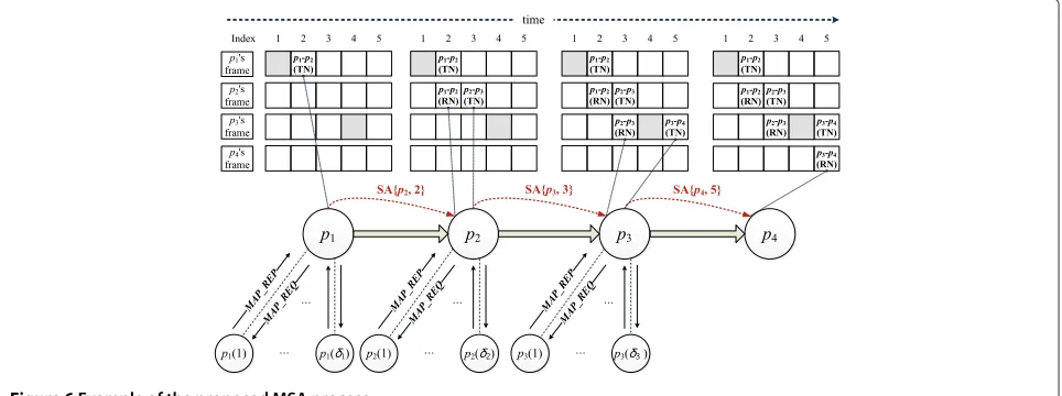
This article presents another example of the proposed MSA process for eliminating any ambiguity regarding the process. Figure 6 shows an example of the proposed MSA process. In Figure 6,p1andp4represent the source node
and destination node in a flow, respectively, andp2andp3
represent the relay nodes. In this example, it is assumed that each node has five (1 to 5) slots.
In each frame in Figure 6, the gray slots are those that have already been allocated by other flows. First,p1
obtains the map information of its neighbors by exchang-ing MAPREQand MAPREP. Then,p1assigns the 2ndslot as
a TN and then sends SA{MACNEXT,Allocated Slot Index}
to p2. When p2 receives SA {p2, 2} from p1, it assigns
the same 2nd slot as an RN. Second, for communication betweenp2andp3,p2assigns the 3rdslot as a TN after it
obtains the map information from its one-hop neighbors. Then, p2 sends SA{p3, 3} to p3. Next, for
communica-tion betweenp3andp4, p3first assigns the 5th slot as a
TN after it obtains the map information from its one-hop neighbors. After finishing the slot allocation,p3sends SA {p4, 5}top4. Finally, the destination nodep4assigns the
5th slot as an RN. After the proposed MSA process is com-pleted, the map status ofp1,p2,p3, andp4beomes ‘11000’,
‘01100’, ‘00111’, and ‘00001’, respectively.
5.3 Global frame length synchronization: GFLS
In this study, all the nodes undergoing the proposed MSA process employ the initial frame lengthLinit.Linitis
calcu-lated as the upper bound of the affordable frame length. After the proposed MSA process is completed, the frame length of all the nodes may be less thanLinitbecause of
slot reuse in the TDMA system [22]. Therefore,Linitneeds
to be reduced for efficiency. In the proposed MSA pro-cess, the slots are always allocated from each source-node side in a flow. Therefore, the slot index allocated by the destination node is the highest one in the flow. After the proposed MSA process is completed, all the destination nodes broadcast that slot index. If a destination node is related to multiple flows, the highest slot index among the slot indices allocated by the destination is broadcast. If a node hears a higher slot index than the one it currently knows, it rebroadcasts the new index. After some prede-termined dissemination time, all the nodes calculate the
global frame length on the basis of the highest slot index they learns, i.e., the global frame length Lproposed = the
highest slot index. Subsequently, all the nodes adjust their frame length toLproposed.
6 Performance analysis 6.1 Overhead analysis
In this section, we evaluate the overhead of the proposed MSA process in terms of the power consumed for the scheduling by all the nodes in the network. The pro-posed scheme gets the map information of its one-hop neighbors in each hop on the path before transferring the SA packet to the next node. Considering all the possible combinations, we find that the total power consumed for scheduling, Ptotal, consists of the following two
compo-nents.
• PMAP: power consumed for exchanging map information by all the nodes.
• PSA: power consumed for transferring SA packets by all the nodes.
First,PMAPcan be represented as
PMAP=PMAP−REQ+PMAP−REP, (4)
wherePMAP−REQ andPMAP−REPdenote the sum of both
the transmitting power in transmitting nodes and the receiving power in receiving nodes when transferring the MAPREQand MAPREPpackets, respectively. In Figure 6,
assuming that all the nodes in the network are evenly dis-tributed, we find thatδ=δ(p1)=δ(p2)=δ(p3)=δ(p4).
Therefore,PMAP−REQcan be calculated as
PMAP−REQ=
In Equation (5),N denotes the total number of nodes; h(i), the total number of hops obtained by theith source
node to transfer its packet to its destination node; δ, the one-hop degree in a node which means the number of one-hop neighbors; lREQ, the length of the MAPREQ
packet;lMAC+PHY, the sum of the overhead in MAC and
physical (PHY) layers; ltotal−REQ, the sum of lREQ and lMAC+PHY; and lACK, the length of the
acknowledge-ment (ACK) packet. Further,ptxdenotes the energy spent
in transmitting a bit over a distance of 1-meter, and prx
denotes the energy spent in receiving a bit.
We can also obtain the value of PMAP−REP by simply
replacingltotal−REQwithltotal−REPas follows.
PMAP−REP=
wherelREPdenotes the length of the MAPREPpacket and ltotal−REPis the sum oflREPandlMAC+PHY.
Similar to the calculation ofPMAP−REQ andPMAP−REP, PSAcan be represented as
PSA=
sum oflSA and lMAC+PHY. Accordingly, the total power
consumed for scheduling by all the nodes is given by
Ptotal=PMAP+PSA. (8)
6.2 Analysis of multihop packet transmission delay
In this section, we derive the average multihop packet transmission delay of the proposed scheduling scheme.
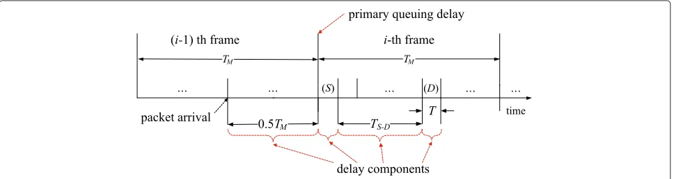
Similar to the analysis in the random link schedule, the delay suffered by a packet,Ds, can be obtained using the following four components (refer to Figure 7): (1) the time between its generation and the end of the current frame, (2) the primary queuing delay to allow all the packets
already queued to be transmitted in a source node, (3) the distance between the first slot and the slot allocated for the destination node, and (4) packet transmission time in both the source and destination nodes. The first component is identical to that in case of the random link schedule, whose value is 0.5TM, and the fourth component, which is the packet transmission time in both the source and destination nodes, is 2T.
To compute the second component, i.e., primary queu-ing delay, (once the end of the current frame is reached), we observe that the queue behaves exactly like the one with a deterministic service time ofTM. If we assume a Poisson arrival process ofλpackets/s for a user and that the number of packets that can be stored in a queue is not bounded, then the primary queuing delay is identical to the queuing time in an M/D/1 queuing system in which the deterministic service time isTM. Thus, the expected primary queuing time of a packet,Wq, is given by [24,25]
Wq= ρ
2(1−ρ)·TM= ρ
2(1−ρ)·Lproposed·T, (9)
whereρ = λ·TM. If we consider a deterministic packet arrival and a deterministic service time, thenWqis equal to zero [15,23].
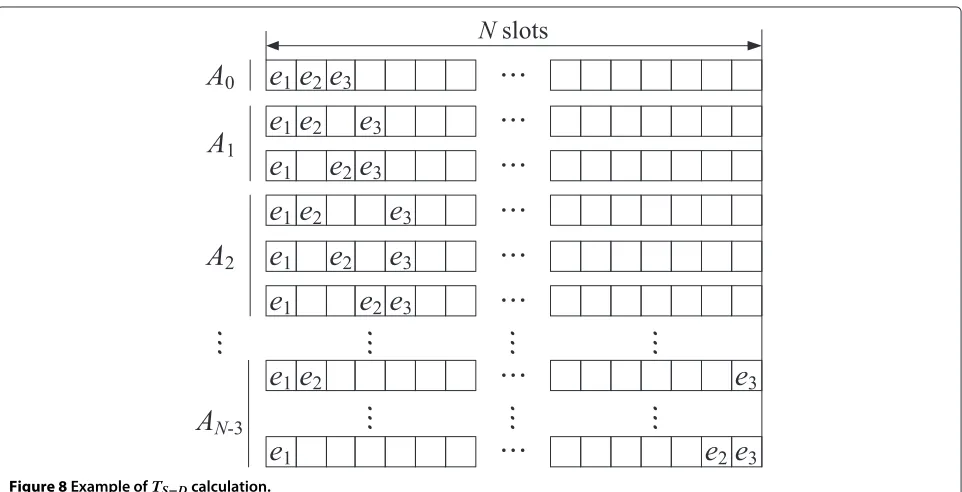
On the other hand, the third component, which is the distance between the first slot and the slot allocated for the destination node,TS−D, can be calculated by averaging all the possible combinations. Figure 8 shows an example of the calculation ofTS−D whenh = 3. First, if there is no vacant slot (A0) among all the allocated slots on the path,
thenTS−DisT and one case (3−2C3−2) exists, whereαCβ denotes the combination of α things taken β at a time.
Second, when there is one vacant slot (A1), TS−D is 2T and two cases (4−2C3−2) exist. Next, when there are two
vacant slots(A2), TS−D is 3T and three cases (5−2C3−2)
exist. Therefore, for allN,TS−Dcan be given by
TS−D= ⎡ ⎣ ⎛ ⎝N
j=h
j−2 h−2
·(j−2) ⎞ ⎠/
⎛ ⎝N
j=h
j−2 h−2
⎞ ⎠ ⎤
⎦·T, (10)
whereN=TM/T. Accordingly, the total multihop packet transmission delay suffered by a packet,Ds, is given by
Ds=0.5TM+Wq+TS−D+2T. (11)
7 Performance evaluation
In this study, we compare the delay performance of the proposed scheme with that of the conventional scheme that uses distance-2 graph coloring. Distance-1 graph col-oring causes the well-known hidden node problem [9,21]. Therefore, it is excluded in this article.
7.1 Simulation scenarios
For the performance evaluation, two scenarios are con-sidered. InScenario#1, we simulate five grid networks to evaluate the delay effect produced by the secondary queu-ing delay. In Scenario#2, a grid network and a random network are simulated for the performance comparison of both the proposed scheduling scheme and the conven-tional graph coloring. InScenario#2, as a consideration of primary queuing delay, we also consider both a deter-ministic packet arrival (DPA) and a non-deterdeter-ministic packet arrival (NON-DPA) having exponential distribu-tion. These two cases are considered for observing the
behavior for both non-constant and constant packet inter-arrival characteristics.
7.1.1 Scenario #1
This article simulatesX byX grid networks, whereXis set to 3, 4, 5, 6, and 7 to observe the queuing behavior of distance-2 graph coloring when only one packet is trans-ferred from each source node. In this network, the vertical and horizontal distances between two adjacent nodes are 30 m, and the communication range of each node is 30 m. After each node allocates slots by distance-2 graph coloring, each source node transfers one packet in its allo-cated slot. If any intermediate nodes receive packets from the previous node on the path, they transmit the received packet in the allocated slot. This study considers ten dif-ferent seeds for this scenario, and their simulation results are averaged.
7.1.2 Scenario #2
To compare the performance of the proposed schedul-ing scheme with that of the conventional scheme usschedul-ing distance-2 graph coloring as carried out in [15], this study simulates two TDMA networks with different topologies. One is the X by X grid network, where X is set as 7. In the grid network, the vertical and horizontal distances between two adjacent nodes are 30 m. The other is the network with 100 nodes randomly distributed in a square area of 200 × 200 m. In both networks, the communi-cation range of each node is 30 m. As soon as all the source nodes complete the proposed MSA process suc-cessfully, they generate packets before transmitting them in the allocated slot. If intermediate nodes receive pack-ets from the previous node on the path, they transmit the received packets in the allocated slot for each flow. For the grid network, this study considers five different seeds. In case of random topologies, this study considers ten dif-ferent random topologies and their simulation results are averaged.
Table 2 summarizes some preliminary results obtained from the simulation. In Table 2, Lcoloring denotes the
Table 2 Some preliminary results
Grid network Random network unit slot time (N=49)0.001 s (N=100)0.001 s
Lcoloring 21 88
Linit 196 440
Lproposed 75 200
one-hop degree 3.35 7.5
two-hop degree 5.67 11.9
h 4 4.4
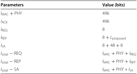
Table 3 Parameter for overhead calculation
Parameters Value (bits)
lMAC+PHY 496
lACK 496
lREQ 8
lREP 8+Lproposed
lSA 8+48+8
ltotal−REQ lMAC+PHY+lREQ
ltotal−REP lMAC+PHY+lREP
ltotal−SA lMAC+PHY +lSA
frame length of the conventional schedule using distance-2 graph coloring andLproposeddenotes the frame length of
the proposed scheduling scheme.
7.2 Numerical and simulation results and discussions
In this section, we first discuss the results of overhead analysis. Next, the simulation results fromScenario#1 are discussed. Finally, the simulation results fromScenario#2 and the related analysis results are discussed.
7.2.1 Results from the overhead evaluation
Table 3 lists the parameters used for calculating the MSA overhead. As same in [9,26,27], ptx and prx are set as
0.1 nJ/bit-m2and 50 nJ/bit, respectively. Table 4 shows the total energy spent by all the nodes for the proposed MSA process. Typically, a distributed network having 100 nodes needs a couple of joules of energy for scheduling [26,27]. In the proposed MSA process, all nodes exchange their table maps for each hop in a flow. Therefore, the energy consumed is slightly more than that consumed in the con-ventional schemes. In particular, if the overhead for the frame length synchronization in Phase II is included, the energy consumed may be slightly greater than that in the results shown in Table 4. However, it is believed that these results are within the acceptable range.
7.2.2 Results from scenario #1
Table 5 summarizes some results from the simulation of Scenario #1, where each source node transfers only one
Table 4 MSA overhead: power consumption
49 nodes (Joules) 100 nodes (Joules)
PMAP−REQ 0.1120 1.2474
PMAP−REP 0.1203 1.4967
PSA 0.0356 0.1769
Table 5 Some preliminary results in graph coloring
# of nodes 9 16 25 36 49
Lcoloring 6 7 18 21 22
h 1.44 2.13 2.72 3.22 4.10
frame delay 2.2 3.5 5.7 7.5 9.4
packet in the first frame. In Table 5,Lcoloringdenotes the
number of slots allocated by distance-2 graph coloring, hdenotes the average number of hops, and frame delay denotes the number of frames elapsed for all the destina-tion nodes to receive one packet from each source node. In conventional minimum length schedules where one com-mon slot is allocated to multiple flows in a link, the factors that may influence frame delay are primary and secondary queuing delays. In this scenario, no primary queuing delay
(a)
DPA with different seed values (49 nodes)(b)
NON-DPA with different seed values (49 nodes)Figure 9Packet transmission delay (seconds).(a)DPA with different seed values (49 nodes).(b)NON-DPA with different seed values (49 nodes).
occurs because each node generates only one packet. Intu-itively, it is said that if the number of hops from a source node to a destination ish, the frame delay ish. However, in Table 5, each network (whenXis 3, 4, 5, 6, and 7) needs 2.2, 3.5, 5.7, 7.5, and 9.4 frames on an average whenhis 1.44, 2.13, 2.72, 3.22, and 4.10, respectively. Accordingly, the increase of the frame delay inScenario#1 is all caused by the secondary queuing delay.
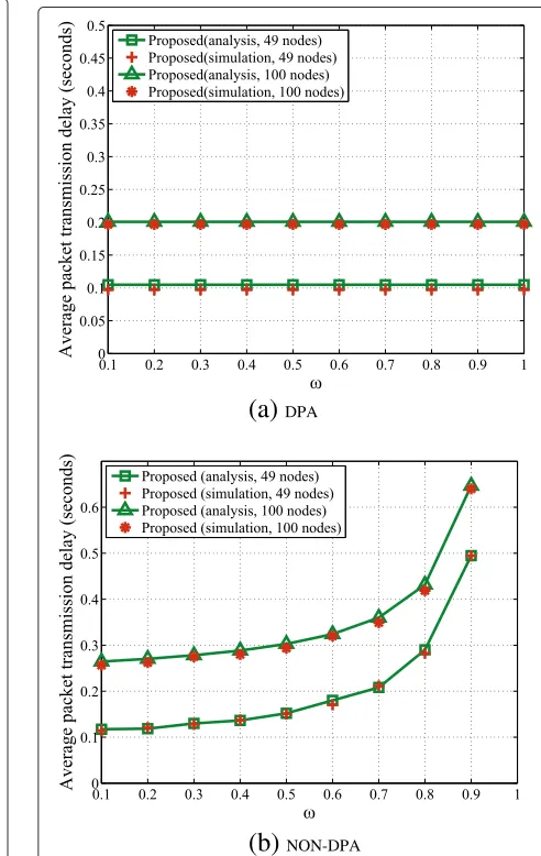
7.2.3 Results from scenario #2
Figure 9 shows the multihop packet transmission delay with different seed values with an increase of the value of ω. In Figure 9, the symbols indicate the simulation results. The packet interarrival time is set as (unit slot time × Lproposed)/ω, where ωincreases from 0.1 to 1 in steps of
0.1. (τ×Lproposed) means a frame length in terms of time
and is the fixed value. If the value ofωis 0.5, then each
(a)
DPA(b)
NON-DPAFigure 10Average packet transmission delay (seconds).(a)DPA.
node generates one packet per two-frame. On the other hand, if the value ofωis 1, then each node generates one packet per one frame. Therefore, increasing the value of ωis the same as the increase of packet interarrival rate. For both DPA and NON-DPA cases, graph coloring shows intolerable delay for some values of ωat different seed values. For example, for seed 1, the multihop packet trans-mission delay is stable untilωis 0.6. In case of seed 4, the delay is stable untilωis 0.7. This is because the network using graph coloring is overloaded in the intermediate nodes. Therefore, the result graph has been drawn with different seed values.
In case of DPA, both scheduling schemes show a sta-ble performance except in the intolerasta-ble cases. How-ever, the proposed scheduling scheme shows a shorter multihop packet transmission delay, even though it starts the packet transmission with slightly greater frame length than that in case of graph coloring. As men-tioned before, graph coloring shares slots (resources) for multiple flows in a link [9]. Therefore, an increase in the frame delay caused by the secondary queu-ing delay causes an increase in the multihop packet transmission delay. For the NON-DPA case, the pro-posed scheme shows slightly longer multihop packet transmission delay. The proposed scheduling scheme is more efficient when there is only one packet wait-ing for the packet transmission at the beginnwait-ing of each frame. If there are more than two packets at the beginning of each frame, then all packets but one packet to be transferred in the current frame experi-ence a long delay because of long frame length. When considering the NON-DPA case in the source node, each source node has the chance to see more than two packets; that is, the primary queuing delay may occur. Therefore, the proposed scheduling scheme shows a slightly lower delay performance for the NON-DPA case. However, the proposed scheme is more toler-able for a high packet interarrival rate than graph coloring.
Figure 10 shows the average multihop packet transmis-sion delay of the proposed scheme with an increase of the packet interarrival rate. In Figure 10, the lines indicate the numerical results and the symbols indicate the simulation results. In this case, we average the results from ten differ-ent seeds. It can be observed that the analytic results are similar to the simulation ones for both cases.
8 Conclusions
This article proposed a new delay-efficient TDMA-based distributed scheduling scheme to eliminate the secondary queuing delay, which may occur in the conventional min-imum length scheduling schemes. We derived the multi-hop packet transmission delay of the proposed scheduling scheme and validated it through a simulation. Finally,
we compared the performance of the proposed scheme with that of the conventional minimum length scheduling scheme that employs distance-2 graph coloring. The important contributions of this study are as follows:
• An intuitive method for eliminating the secondary queuing delay.
• Analysis of the delay effect caused by an allocation sequence of the TDMA slots.
• A distributed method to sequentially allocate slots on a path.
• Analysis of the proposed scheme and its simulation.
According to the simulation and analysis results, for the DPA case, the proposed scheme works well irrespective of the packet interarrival rate and outperforms the con-ventional graph coloring. However, in case of NON-DPA, the multihop packet transmission delay of the proposed scheme is slightly longer than that of the conventional graph coloring because the probability that each node has more than two packets increases at the beginning of the frame. However, the proposed scheduling scheme is more tolerant for a high packet interarrival rate.
9 Future study
In the future studies, first, we intent to extend the pro-posed scheduling scheme to an autonomous environment where either new nodes can efficiently assign time slots or existing nodes can release their slots on a path in a dis-tributed manner. Second, the proposed scheme has the characteristics that each node allocates a different slot to each flow in a link. Therefore, it needs lots of slots; how-ever, the distance-2 coloring leads to slightly smaller frame length because each node allocates one common slot for multiple flows in a link. This study have considered a sit-uation wherein each node has only one flow. However, it is somewhat unrealistic. If two flows are considered per node, the frame length of the proposed scheme is up to two times greater than that when considering one flow per node. Accordingly, we are also interested in reducing the frame size and in concurrently reducing the network load by using conventional network coding (NC) schemes.
Competing interests
The authors declare that they have no competing interests.
Acknowledgements
“This research was supported by the Ministry of Knowledge Economy (MKE), Korea, under the Information Technology Research Center (ITRC) support program supervised by the National IT Industry Promotion Agency (NIPA)” (NIPA-2012-(C1090-1221-0011)), “This study had been supported by National GNSS Research Center program of Defense Acquisition Program
Administration and Agency for Defense Development”.
References
1. V Gabale, B Raman, P Dutta, S Kalyanraman, A classification framework for scheduling algorithms in wireless mesh networks. IEEE Commun. Surv. Tutor.PP(99), 1–24 (2012)
2. K Jain, J Padhye, VN Padmanabhan, L Qiu, Impact of interference on multi-hop wireless network performance. Wirel. Netw.11, 4471–4487 (2005)
3. S Ramanathan, A unified framework and algorithm for channel assignment in wireless networks. Wirel. Netw.5(2), 81–94 (1999) 4. S Ramanathan, EL Lloyd, Scheduling algorithms for multihop radio
networks. IEEE/ACM Trans. Netw.1(2), 166–177 (1993)
5. B Hajek, G Sasaki, Link scheduling in polynomial time. IEEE Trans. Inf. Theory.34(5), 910–917 (1988)
6. T Salonidis, L Tassiulas, inProc. ACM MobiHoc. Distributed dynamic scheduling for end-to-end rate guarantees in wireless ad hoc networks (IL, USA, 2005), pp. 145–156
7. M Kodialam, T Nandagopal, Characterizing achievable rates in multi-hop wireless mesh networks with orthogonal channels. IEEE/ACM Trans. Netw.13(4), 868–880 (2005)
8. G Sharma, R Mazumdar, N Shroff, inProc. ACM Mobicom. On the complexity of scheduling in wireless networks (CA, USA, 2006), pp. 227–238
9. S Gandham, M Dawande, R Prakash, inProc. IEEE INFOCOM, vol. 4. Link scheduling in sensor networks: Distributed edge coloring revisited (TX, USA, 2005), pp. 2492–2501
10. S Sarkar, K Kar, inProc. 44th Annu. Allerton Conf. Communication, Control and Computing. Achieving 2/3 throughput approximation with sequential maximal scheduling under primary interference contraints (IL, USA, 2006), pp. 5342–5347
11. M Sanchez, J Zander, T Giles, inProc. WPMC, vol. 2. Combined routing and scheduling for spatialTDMA in multihop ad hoc networks (Honolulu, Hawaii, 2003), pp. 781–785
12. H-Y Wei, S Ganguly, R Izmailov, Z Haas, inProc. IEEE VTC Spring, vol. 5. Interference-aware IEEE 802.16 WiMax mesh networks (Stockholm, Sweden, 2005), pp. 3102–3106
13. B Han, W Jia, L Lin, Performance evaluation of scheduling in IEEE 802.16 based wireless mesh networks. Comput. Commun.30, 782–792 (2007) 14. D Ghosh, A Gupta, P Mohapatra, inProc. Mobile Adhoc and Sensor Systems.
Admission control and interference-aware scheduling in multi-hop wimax networks (Pisa, Italy, 2007), pp. 1–9
15. P Djukic, S Valaee, Delay aware link scheduling for multi-hop tdma wireless networks. IEEE/ACM Trans. Netw.17(3), 870–883 (2009) 16. J Zou, D Zhao, Real-time cbr traffic scheduling in ieee 802.16-based
wireless mesh networks. Wirel. Netw.15(1), 65–72 (2009)
17. G Narlikar, G Wilfong, L Zhang, inProc. INFOCOM. Designing multihop wireless backhaul networks with delay guarantees (Catalunya, SPAIN, 2006), pp. 1–12
18. A Sahoo, P Goyal, inProc. COMSNETS. A scheduling and call admission control algorithm for wimax mesh network with strict qos guarantee (Bangalore, India, 2010), pp. 20–29
19. V Gabale, A Chiplunkar, Raman Bhaskaran, Dutta Partha, inProc. COMSNETS. Delaycheck: Supporting voice over multi-hop multichannel wireless mesh (Bangalore, India, 2011), pp. 1–10
20. IEEE 802.11s,Draft Amendment: ESS Mesh Networking, (2006) 21. I Rhee, A Warrier, J Min, L Xu, DRAND: distributed randomized TDMA
scheduling for wireless ad hoc networks. IEEE Trans. Mob. Comput , 1384–1396 (2009)
22. C Zhu, MS Corson, inProc. IEEE INFOCOM. A five-phase reservation protocol (FPRP) for mobile ad hoc networks (CA, USA, 1998), pp. 322–331 23. SJ Golestani, A framing strategy for congestion management. IEEE J. Sel.
Areas Commun.9(7), 1064–1077 (1991)
24. R Rom, M Sidi,Multiple Access Protocols: Performance and Analysis. (Springer Verlag, New York, 1990)
25. S Dastangoo, TG Macdonald, D Reinharth, C Burns, inProc. MILCOM. Performance analysis of distributed time division multiple access protocols in mobile ad hoc environments, (USA, 2009), pp. 1–7
26. S Gandham, M Dawande, R Prakash, S Venkatesan, inProc. IEEE Globecom. Energy efficient schemes for wireless sensor networks with multiple mobile stations (San Francisco, USA, 2003), pp. 1108–1120 27. WR Heinzelman, A Chandrakasan, H Balakrishnan, inProc. HICSS.
Energy-efficient communication protocol for wireless microsensor networks (Hawaii, USA, 2000), pp. 3005–3014
doi:10.1186/1687-1499-2012-369
Cite this article as:Kimet al.:New delay-efficient TDMA-based distributed
schedule in wireless mesh networks.EURASIP Journal on Wireless
Communi-cations and Networking20122012:369.
Submit your manuscript to a
journal and benefi t from:
7Convenient online submission 7Rigorous peer review
7Immediate publication on acceptance 7Open access: articles freely available online 7High visibility within the fi eld
7Retaining the copyright to your article