A RENAISSANCE IN THE USE OF THE SMALL PUNCH TESTING
TECHNIQUE
Roger C. Hurst1,Karel Matocha2
1Honorary Professor, Institute of Structural Materials, Swansea University, 2 Director, Material & Metallurgical Research, Ostrava, Czech Republic
ABSTRACT
This paper is intended to evaluate whether the CEN CWA 15627 “Small Punch Test Method for Metallic Materials” has indeed succeeded in providing a stimulus for a wider implementation of the small punch test technique in industrial applications throughout Europe and indeed worldwide since its first publication in 2006. Significant research progress has been achieved, as strongly evidenced in three dedicated SSTT (Small Specimen Testing Techniques) conferences held in Europe over the last five years, but also in the wider literature. There has also been the recent publication of a Japanese standard and the announcement of parallel progress in China but the present paper concentrates on progress within Europe from the launch of the Code to the present day. In particular, attention is focused on the need for industrial acceptance of the test methodology and methods for evaluating the results where some scepticism still seems to prevail. Nevertheless the technique is still applied within the original remit for nuclear inspection, continues to be strongly considered for application in the conventional power generation sector judging from the extent of tests on power plant steels and shows interest in development for aerospace and next generation nuclear applications enhancing further the credibility of the Code.
INTRODUCTION
The residual lifetime assessment and potential for possible failure of in service components is a critical issue in the safety and reliability analysis of industrial plants, in particular for operating nuclear and conventional power stations and petrochemical plants which are approaching the end of their design lives. For decades, since those plants were built, several degradation processes may have potentially impaired the mechanical integrity of their structural components. At the time of construction, the design life was based on relatively simplistic codes endorsed by practical experience and finally adjusted by an
appropriate safety factor. Indeed, in light of the major advances in metallurgical knowledge and currently available analytical methodologies, today it would be possible to reduce the safety factors and to thus extend design lives. In addition, the new policies for environmental protection and the safety regulations for industrial plants make it more practical and economically convenient to extend the lifetime of existing components beyond their original design life rather than to build new plants. However, major investment to modernize and make more efficient existing plants is only profitable if the plant under consideration has sufficient residual life. Hence, reducing the uncertainty in the estimation and monitoring of remaining life of plant components is of fundamental importance to industry.
whereas Parker and James (1993) proposed its use for determining the creep properties of components operating at elevated temperatures. It has become to be more widely known in Europe in recent years. The SP test can be considered as effectively a non-destructive technique because of the very limited amount of material to be sampled, with the specimens being discs 0.25 – 0.5 mm thick and 8 - 10 mm diameter. It is an efficient and cost-effective technique and has the potential to enable measurement of the realistic material properties for the specific component, identifying the present state of damage and focusing on the more critical (highly stressed, more damaged) locations in the component. Acceptance of the use of the technique by plant operators is however another question. This creates a vicious circle, which is difficult to break, in that the low level of acceptance in turn causes the technique to have seen only limited use and therefore can hardly be validated. Promoting the use of the technique strongly depends on the usefulness of the test results for the industry. Both the test methodology and the interpretation of results can lead to doubts and only the imposition of a standard covering both testing and analysis will convince the potential users of the benefits of extensively employing the technique. As a first step, a Code of Practice was developed in Europe starting in 2003 culminating in a CEN Workshop Agreement (2007), CWA 15627, comprising two parts, Part A: A Code of Practice for Small Punch Creep Testing, and Part B: A Code of Practice for Small Punch Testing for Tensile and Fracture Behaviour.
Since the launch of the Code of Practice an additional market has developed around the small punch testing method with a completely different purpose than the remanent lifetime evaluation originally envisaged. This centres on the specific ability of the technique to assess the mechanical integrity of small quantities of material as well as unique zones in materials. Materials development is usually an expensive and time consuming process, particularly when it comes to novel applications. The advantages in producing small quantities of different materials and being able to evaluate their creep, tensile and fracture behaviour thereby underpinning materials selection is clearly afforded by the small punch testing method. Examples of use of the method are becoming numerous within the aerospace industry where materials are needed to withstand demanding conditions such as extreme temperatures and higher loading in the need to improve engine efficiency and reliability. In such cases, not only can exotic monolithic materials, such as single crystals or directionally solidified alloys be studied but also small-scale deposition structures can be evaluated even down to their constituent layers. In the same way other zones of interest in components can be studied such as those making up a weldment or joint which can be crucial in determining the mechanical integrity in many components and applications, whether conventional or novel. Further, within the next generation fission and fusion nuclear industry there have been specific developments towards alloys constructed through the powder metallurgical route, again capable of withstanding exposure conditions not previously encountered in the conventional nuclear industry. Here, just as for aerospace materials the SP technique facilitates attention to be focused on important factors for engineering design, such as material anisotropy.
EXPERIENCE WITH APPLYING THE CODE OF PRACTICE FOR CREEP TESTING
The main elements of Section A of the Code which deals with Small Punch Creep Testing, cover the apparatus, the test-pieces, the test procedure and the crucial analysis element, which is intended to facilitate the interpretation of the test results. As far as the experimental apparatus is concerned the main recommendation is for all test laboratories to adopt a prescribed geometry based on a 2-2.5mm diameter hemispherical punch, a 4mm diameter receiving hole with a 45o chamfered lip. The apparatus should also
2.0 or 2.5mm. The deflections, which are to be measured are at the upper surface of the disc, u1, indicated
by travel of the punch, and at the lower surface u2, indicated by the travel of a push rod transducer.
Figure1 Geometry of the SP test installation according to the CoP
A number of laboratories, not just within Europe, and including those of the authors have continued with SP creep and high temperature tensile testing since the original launch of the Code of Practice in 2006. A wide range of materials have been tested including P91/92 weldments by Blagoeva and Hurst (2009), Gulcimen et al (20013), Ma et al (2009), Zhao et al (2013), Milicka and Dobes (2006)); P24 weld metal by Sturm and Grum (2012); a welded P22 header steel by Tonti et al (2012); ODS steels by Turba et al (2012) and Bruchhausen et al (2014); MCrAlY coatings by Chen et al (2013); chromium and low alloy steels by Singh et al (2014) and Nishioka et al (2010); Al-Al4 C3 by Dobes et al (2012); Fe-Al alloys by
Dobes and Milicka (2010); Ti-Al alloys by Norton et al (2012) and Lancaster et al (2014); repair welded IN718 alloys by Hurst et al (2013) and Lancaster et al (2014) and finally nickel base turbine alloys by Cammi et al (2009). All tests have been carried out in the range 200o C to 900o C and in nearly all cases
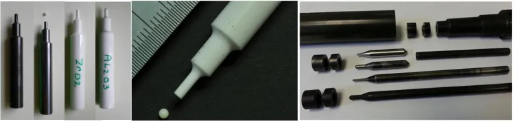
the testing procedures outlined in the CoP have been accurately followed. Slight exceptions have occurred with regard to specimen dimensions, external diameters of 9.5mm and 10x10mm square specimens have been used but as would be expected and shown by Zhou et al (2010) providing the surface area outside the 4mm receiving hole is firmly clamped this should play no role. In their paper, Zhou et al studied both an austenitic and a ferritic steel and closely examined sensitivity to key test parameters and analysed these using FEM coupled with continuum damage models. Had they compared their results with the Code of Practice methodology this work could have been an extremely useful contribution towards validation. Some concern has been raised related to the choice of the large punch size of 2.5mm with a 4mm receiving hole although this is considered as the limit as the clearance should be substantially greater than the disc thickness otherwise the test would approach the conditions for a shear test and not a small punch bulge test according to Ule et al (2003). Also disc thicknesses have not always been 0.5mm, Madia et al (2013) used 0.43mm and Turba et al (2012) used 0.47mm. Some authors could only achieve a thickness tolerance of ±10µm compared to the recommended ±5µm. Where it is mentioned most authors confirm the use of a chamfer on the lower die with either 0. 2mm increase in diameter and a 45 o lip or a curved lip of 0.2mm radius as used by Kobayashi et al (2011). The punch radius was always either 1.0 or 1.25 mm whether a solid punch or ceramic ball was utilized. A wide range of punches and ceramic balls has been utilized including tool steels, Nimonic alloys, single crystals, alumina and zirconia, depending on strength and temperature requirements (Fig.2). Nevertheless there remains an open question from Allen (2009)
1- SP disc test specimen, 2- 2- hemispherical
ended punch 3- lower die, 4- upper die, 5- deflection
Figure 2 A variety of solid punches and ceramic balls
concerning the possibility to employ a non-hemispherical indenter with a much larger radius than 2.5mm with the professed aim of promoting failure in the flanks of the test-piece rather than close to the crown. Although the present authors are aware of some developments in this area by Bruchhausen (2013) results are not yet available in the open literature. With regard to annular clamping nearly all laboratories favour this testing mode, as full clamping removes uncertainty regarding positioning and movement of the disc under load. Of course this also has consequences for interpreting the load applied in terms of stress.
With regard to test procedure there appeared only to be a single author, Chen et al (2013), testing in air rather than argon however the test material is a highly oxidation resistant coating and for relatively short term tests this could be considered acceptable but of course not ideal for inter-laboratory comparisons where the other laboratories might use argon. A number of authors have confirmed that these thin discs need to be taken to temperature relatively quickly but smoothly and for such low thermal mass disc the argon flow rate must also be controlled. Most laboratories recognize the problem of accurate measurement of the disc temperature and some apparatus configurations facilitate placing the thermocouple tip as close as possible to the test-piece, for example at the tip of the lower dilatometer push rod or through the upper die pushed against the clamped annulus. All laboratories seem to be now including a calibration procedure whereby a thermocouple is spot-welded to a dummy specimen and the relationship between the temperatures derived from this thermocouple compared to the measurement thermocouple is carefully determined. There is also agreement that the load definitely has to be applied in a smooth manner and most laboratories now use micrometer screws, pneumatic or hydraulic jacks to ensure a controlled and rapid transfer of load compared to the older approach of adding weights one after the other. In Japan, Nonaka (2009) and Komazaki (2009) have reported on the extensive experimental and analytical trials with a variety of dimensions of punchers but also of receiving holes and test-piece thickness and even test-piece size (7 – 10mm) and shape (round or square). Their results show that the test load/stress ratio, FSP/σ, indeed increases with puncher diameter and disc thickness and decreases as
the receiving hole increases, just as in the Code equation. The proposed route involving the von Mises equivalent stress at steady state looks extremely promising and a direct comparison with the Code equation is eagerly awaited when the JSMS test standard announced by Nonaka (2012) will be available.
Whereas the consensus concerning the experimental approach proposed in the Code of Practice is close to being reached, the most crucial aspect for the Code to be finalised and transformed into a testing standard concerns the evaluation of the results and as mentioned earlier in particular the interpretation of the stress equivalent to the load applied in the test in order that the plant designer/operator can be convinced. In the CoP, for this reason, an annex is supplied which details the approach adopted to lead to a recommended relationship between the test load and the comparable creep stress as:
This relationship has been derived from stretching membrane theory but is clearly empirical in nature with the constant kSP being considered as an indication of the creep ductility of the material. This
relationship has a double purpose. First of all it is to be used for calculating the appropriate loads to be used in the SPT creep test, usually based on some estimate of uniaxial behaviour of a particular material and secondly, and more importantly, for establishing the test stress from the SP test applied load facilitating the evaluation and acceptance of the test results. Results obtained in the author’s laboratory by Blagoeva and Hurst (2009) around the time of publication of the Code of Practice showed how kSP values
could be determined using the CoP relationship for a repair welded service exposed P91 steel component as shown in Fig. 3.
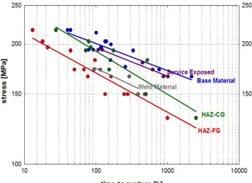
Figure 3 Comparison of SP tests with uniaxial tests for a) P91 steel in the as received and service exposed condition indicative of a kSP = 1.2 and b) P91 weld metal representing a kSP = 1.0
Such parameters were impossible to determine for individual constituents of the HAZ in a weldment because it is almost impossible to obtain specimens of sufficient size to carry out the necessary uniaxial creep programme of testing. Nevertheless, the relative performance of individual components of the weld microstructure (Hurst and Matocha (2012)) can be interpreted from Fig. 4. Similar conclusions as to the usefulness of the SP technique for comparing the creep resistance of the zones of a P92 weldment were
Figure 4 Relative performance of individual components of a weld microstructure for P91 weldment
recently drawn by Kobayashi et al (2010). Even more recently, Zhao (2013) has applied the Code of Practice to P92 weldments revealing kSP values of 1.035 and 0.977 for the Base metal and Weld metal
Holmstrom et al (2014) derived the strength reduction factors and local constitutive creep model for welds and constituent parts, from the SP deflection curves using the Wilshire et al (2007) rupture model.
Although much consensus has been achieved in the literature about the SP testing procedure, the method of relating load in the SP creep test to the equivalent uniaxial stress is still open to debate as already discussed above for P91 and P92 welded steels. When testing Al/Al4C3 composite materialDobes at al
(2012) have derived an unusual value for kSP of 0.5. A similar value below unity (0.6) has been found by
Norton et al (2012) for a brittle γTiAl intermetallic alloy but importantly the SP load and uniaxial stress values do not lie parallel to each other when plotted as in Fig. 5a. Hence the value found for kSP is only
really valid about the crossover points in the curves and is useful for setting up the test matrix but is not applicable for analyzing the results of the tests. The authors have recognized this and developed their own empirical relationship between SP load and equivalent uniaxial stress in a simplified way as SP Load =
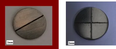
36.167σ0.333. Also they observed a completely different type of failure in these tests on a relatively brittle
material as shown in Fig. 5b. The SP disc does not fail by circumferential cracking in the weakest position consistent with membrane stretching but relatively early in the test by star type cracking directly above the punch.
Figure 5 a) SP and uniaxial creep test results on γ TiAl at 700oC and 750oC and b) deformed SP test disc
at 50% life
Finite element analysis of the evolution of the stresses within the disc early in the test show high maximum principal stresses at the beginning of the test and it is therefore possible that for a brittle material these stresses can lead to star type fractures. The final fractures in such cases have little to do with membrane stretching and it is possible that the applied loads can be resisted even though the disc appears to be severely cracked because there is no thinning around the circumference where stretching would have been predicted for a ductile material. A similar situation is revealed during the testing of newly developed γTiAl alloys by Lancaster et al (2014) where again star-type cracking is observed,Fig. 6.
a) b)
Even for ductile materials alternatives to the CoP equation (1) have been proposed by Chen et al (2013), Chen et al (2010) and Ma et al (2009) along with the ‘General’ strain approach by Hyde et al (2014). A new evaluation scheme based on the deflection curves from individual tests by Gulcimen and Haehner (2013) was expected to give a better explanation for the evolution of effective stresses both in the early stages of the test where bending and pronounced initial yielding occurred but also during pronounced thinning, however, according to the authors, the small difference between the results derived from this method for the zones of a P91 weldment compared to the CoP results are indicative of other factors such as possibly strain hardening which should be introduced into their effective stress based methodology. Other approaches usually involving FEA have concentrated on effective stress values and even Reference Stress as reported by Rouse et al (2013) in a very recent and thorough review, although the Reference stress concept does not fit well with the remarkable shape changes which occur in the SP test. With regard to the material model to be selected for FEA analysis with relevance to their application in the membrane stretching theory used in the Code of Practice, different options to the Norton Law such as a unified Chaboche-type, a two layer visco-plastic and a Kachanov-Rabotnov damage model have been applied in different laboratories. The idea of the physical based model is to provide an alternative to kSP, which is
purely empirical, and possibly both load and material dependent. FEA analysis has been used by Zhou et al (2010) to contribute to the understanding of the roles of punch/disc contact and friction during the SP creep test as also Dymacek et al (2010) and Hyde et al (2012). The latter authors rightly express concern that coefficients of friction, although difficult to determine at elevated temperatures, are not introduced into the relationship between SP load and uniaxial stress in the Code of Practice.
This dilemma concerning the relationship between SP load and equivalent uniaxial stress also applies to anisotropic materials, such as for the ODS alloy MA956 of Turba et al (2012) where the SP test could not be applied to determine the maximum strength as given by the material’s manufacturer because of the biaxial stress applied in such a test. The SP test on a disc with strong grain orientation only gains partially from the high strength longitudinal properties as shown in Fig. 7. In more recent work on a 14Cr ODS steel under development for next generation nuclear reactor applications Bruchhausen et al (2014) found inferior creep behavior compared to MA956 using a Larson-Miller plot. However they again demonstrated the clear effect of SP disc orientation and the non-applicability of the Code’s kSP approach,
and suggested that minimum deflection rates would show less scatter than stress rupture results. In spite of the fact that equivalent uniaxial stresses cannot be derived for anisotropic materials, just as for Heat Affected Zones, the SP test will be useful for ranking materials such as those developed in small quantities on a laboratory scale for advanced applications.
Other uses of the SP creep testing technique for ranking materials have been particularly exploited for aerospace applications. Cammi et al (2009) examined nickel based turbine alloys, ranking their creep properties not only in the as received condition but also after service ageing. Lancaster et al (2014) have similarly been able to characterize small scale material addition structures using IN718 and deduced important information related to the micro-texture of deposition microstructure and Lancaster et al (2011)
have been able to rank the creep resistance of development γ TiAl alloys and previously also Niobium Silicides through Hurst et al (2013)
PROPOSALS FOR IMPROVEMENT OF THE SP CREEP CODE (PART A) AND FURTHER SUPPORT WORK
In addition to corrections of typographical errors, particularly in Annex A1, there are some specific changes, which could be introduced due to the consensus already reached amongst those using the Code of Practice. The following items should be considered as agreed or likely to meet agreement:
1. The use of a ceramic ball is no longer “not recommended” (to be corrected in CoP 3.1)
2. A square shaped disc can be used when fully clamped providing its dimensions are greater than 8mmx8mm (to be added to 4.1)
3. The disc thickness may lie in the range 0.45 – 0.55mm and the actual thickness be reported 4. In order that the deformed disc can travel through the receiving hole it is recommended to
introduce a statement that D must be greater than 2r +2h0 (in 3.1)
5. The chamfer can be at 450 with dimensions 0.2mm x 0.2mm or curved with a radius of 0.2mm
(correct 3.1)
6. The dimension of the receiving hole (diameter D) may need redefining as D+0.4mm with a decision required in view of the consequences for the equation in 5.2
7. The correction factor of 20% for clamped/unclamped load may need to be corrected in 5.2 when consensus is agreed after further work (see below)
8. Punch velocities should probably given in mm/min as well as m/s in both part A and Part B Table1’s and a decision made to use V or v
9. The stress units changed to MPa in Table 1 10. The disc should be finally finished with 1200 grit
11. The thickness tolerances should be equal for Part A and Part B or explained if they are different 12. An inspection of the puncher or ceramic ball should take place prior to each test and the puncher
or ball replaced if changed by ±1% in diameter
13. Elevated temperature tensile testing will only fall under the CoP Part B with some appropriate modification and improvements recognizing the special requirements needed for the higher temperature ranges up to 12000C
There are a number of items where further discussion and work is required, in particular those identified above with regard to confirming a suitable relationship between the SP load and the equivalent stress in a uniaxial test. In addition it may be useful to carry out some round robin validation testing to confirm the applicability of the test methodology to a range of materials. It is important to confirm that the analysis involving Chakrabarty equations only applies to ductile creep failure evidenced through circumferential cracking at the weakest position. The occurrence of cracking directly under the punch and resulting in a so called star fracture is no doubt unrelated to the stretching failure model and a companion analysis route for relating SP load to uniaxial stress should be given in the CoP . Further, taking into account that this cracking may initiate during the early highly loaded part of the test it may also be necessary to prescribe test methods that avoid the high bending loads and any such changes will have to be introduced into the test methodology. In order to resolve as many of the above-mentioned uncertainties for incorporation into the CoP (PartA Creep) there is no doubt that a coordinated joint programme of work had to be launched in order to transform the final CoP into a European or ISO standard.
EXPERIENCE WITH APPLYING THE CODE OF PRACTICE FOR TENSILE AND FRACTURE TESTING
considerations, the test procedure, the post-test examination and the approaches to the derivation of yield strength (YS), ultimate tensile strength (UTS), DBTT (Ductile Brittle Transition Temperature) measured by FATT or 41J absorbed energy transition temperature (TT), and fracture toughness from SP tests results. The Code takes into consideration only the Small Punch Bulge (disc clamped peripherally between two dies) and the Small Punch Drawing test (disc simply supported) but not the Shear Punch test even though this test has been one of the most attractive techniques for evaluating tensile properties due to its simple loading configuration and close resemblance of the resulting load-displacement curve to a tensile test curve according to Kasiviswanathan et al (2012). Disc shape test specimens with d = 8 mm in diameter and initial thickness of h0 = 0.5 mm are recommended for both the SP Bulge and SP Drawing
tests. This thickness of 0.5 mm is intended to assure the number of grains through the thickness is adequate to permit bulk properties to be obtained. As far as the experimental apparatus is concerned a screw-driven testing machine is usually used for SP tests. It is equipped with a test rig for holding and loading the test specimen and with a load and displacement/deflection measuring system. The testing rig with a 4 mm diameter receiving hole with a 0.2 mm x 45 degree chamfered lip and hemispherical tipped punch, 2,5 mm in diameter are recommended. However Frialit ceramic balls with radius r = 1 mm or 1, 25 mm may be used for determination of tensile properties at elevated temperatures. SP tests at temperatures ranging from -196°C up to 450°C may be carried out in air but at higher temperatures and for easily oxidised materials an inert environment is envisaged.. The method of temperature measurement must be sufficiently sensitive and reliable to ensure that the temperature of the specimen is within ± 3 K of the planned test temperature. The objective of the test is to produce a load-displacement (punch/, crosshead displacement or specimen deflection)) record (see Fig. 9) which contains information about the elastic-plastic deformation and strength properties of the material. A displacement rate of the punch in the range between 0.2 to 2 mm/min. is recommended. The following SP related parameters are used for determination of YS, UTS, FATT and fracture toughness JIC from such a load - displacement curve:
Fm [N] - maximum load recorded during SP test,
Fe [N] - load characterising the transition from linearity to the stage associated with the spread of a
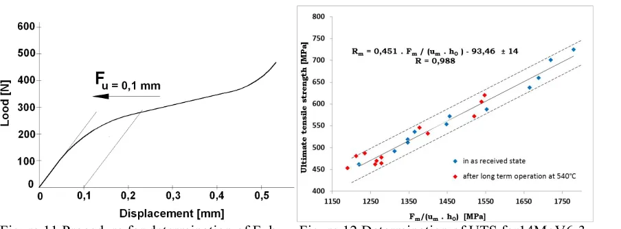
yield zone through the specimen thickness, determined by two tangents method, Fig.8, um [mm] - displacement corresponding to maximum load Fm,
uf [mm] - displacement corresponding to load Ff = 0.8. Fm,
ESP [J] - SP fracture energy obtained from the area under the load - displacement curve up to the fracture (uf).
The load - displacement curves obtained can be utilised to derive empirical correlations between SP and standardised test results [46-53] or they can be analysed in terms of elastic-plastic finite element methods [54-59]. Both of the above mentioned approaches are used at the present time for determination of YS, UTS and JIC. However, ductile-brittle transition temperature (DBTT) measured by FATT and/or 41J
absorbed energy TT is determined only using empirical correlations given in Gulcimen at al (2013), Kobayashi et al (2010), Parker et al (1989), Eto et al (1993), and Foulds and Viswanathan (1994).
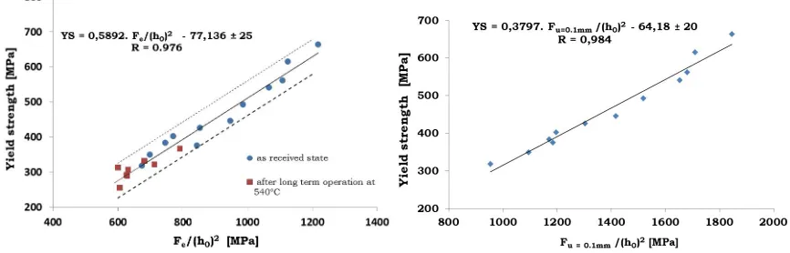
Determination of actual Yield Strength and Tensile Strength on the basis of empirical correlations.
Empirical correlations for the determination of the yield stress from the results of SP tests are usually expressed as the dependences of the yield stress on the parameter Fe/(h0)2 according to Song et al (2012),
Shah and Chatterjee (2006), Purmensky and Matocha ((2009), Kundan et al (2006) and Cueste and Alegre (2012) because this parameter eliminates any differences in disc specimen thicknesses on load Fe as stated
by Hurst and Matocha (2012). Similarly, the authors show that determination of ultimate tensile strength (UTS) from the results of SP tests is usually expressed as the dependence on the parameter Fm/(um. h0)
because it eliminates any differences in disc specimen thicknesses on Fm and um. Figures 9 and 10 show
the empirical correlations obtained by Matocha (2012) for 14MoV6-3 steel tubes in as received state together with the results obtained on steam pipes made of the steel after long term operation at 540°C. Disc test specimens 8 mm in diameter and 0.5 mm in thickness were oriented in R-L direction (simulating removal of testing material by the scoop cutter sampling technology proposed by Parker et al (1989)). It is evident that the empirical correlations obtained for the steel in as received state are also valid for the determination of actual tensile properties after long term operation. Use of the offset method (offset displacement of 0.1 mm) for determination of Fe, instead of the procedure described in the Code (two
tangents method) resulted in lowering of scatter band of the empirical correlation (see Fig. 10). In this case Fe represents the point in the load – displacement curve where fully plastic behaviour takes over
from mixed elastic-plastic behaviour (see Fig.11). For this steel exhibiting a sharp yield point the empirical correlation for determination of tensile strength shows a significantly lower scatter band (Fig.12) in comparison with correlations for yield strength determination.
Figure 9 Empirical correlation for determination of Figure 10 Empirical correlation YS vs. Fe
YS for type 14MoV6-3 steel in as received state /(h0)2 for Fe = F u = 0,1 mm determined for
Figure 11 Procedure for determination of Fe by Figure 12 Determination of UTS for14MoV6-3
offset method (offset displacement of 0.1 mm). steel in as received state and after long term operation
Determination of the DBTT Value from SP Testing
Empirical correlations for DBTT estimation are based on the fact that steels exhibiting standard Charpy impact ductile to brittle transition behaviour also show the transition behaviour in the temperature dependence of fracture energy of the small punch tests, but shifted to a lower temperature as found by Eto et al (1993), Foulds and Viswanathan (1994),Bulloch (1998), Matocha et al (2007), Suzuki et al (1993) and Petzova et al (2012). The fracture energy of the small punch test is calculated from the area under the load – displacement curve until the specimen failure (punch displacement of uf). According to the CEN
Code (2007) the Small Punch transition temperature TSP is defined as the temperature corresponding to
half of the sum of the maximum and minimum fracture energy calculated by the method of least squares from the temperature dependence of fracture energy derived from the experimentally measured data in transition areas. Transition temperature TSP, measured in a series of SP tests typically ranging from
-193°C to laboratory temperature such as obtained by Matocha et al (2012) and Turba et al ((2012) is correlated with the DBTT determined from a series of Charpy V impact tests in the form:
TSP = α. DBTT or TSP = α. DBTT + β (2)
where TSP and DBTT are in degrees K and α, β are constants. The transition temperature TSP and thus the
empirical correlation DBTT vs. TSP can be affected by the following factors according to Hurst and
Matocha (2012), Turba et al (2011), Bulloch (1998), Matocha et al (2012), Li and Vulpen (2012) and Gai et al (2002):
1) type and condition of the material, 2) orientation of the disc test specimen,
3) punch tip diameter,
4) microstructure inhomogeneity,
5) use of notched disc test specimens,
6) method used for the determination of SP fracture energy ESP
7) loading rate
Pracice, the SP test orientation is such that the normal to the punch disc plane is parallel to Charpy specimen crack propagation directions. Figure14 from Hurst and Matocha (2012) shows the effect of orientation of the disc on transition temperature TSP determined from the temperature dependence of
fracture energy ESP for discs taken in the direction T-L (in accordance with CWA 15627) and discs taken
from a 14MoV6-3 steel pipe ø219x16 mm by SSamTM-2 in the R-L orientation. The results of SP tests
indicate significant effect of test specimen orientation on the temperature dependence of fracture energy mainly in the transition area.
Figure 13 Temperature shift of the SPT energy Figure 14 Effect of orientation of test disc on TSP
curves for RPV materials due to irradiation determined for 14MoV6-3 service exposed pipe steel
Figure 15 displays the effect of punch tip diameter (2.0 mm, 2.5 mm) on the temperature dependence of fracture energy of the steam piping made of 14MoV6-3 steel in as received state. The results show that in the transition region the temperature dependence of fracture energy and hence transition temperature TSP
is not affected significantly by punch tip diameter. Figure 16 presents the temperature dependence of fracture energy obtained for cast P91 steel plate.. It is evident that temperature dependence of fracture energy ESP in the transition region shows considerable scatter covering the range the T
SP from 142K to
154K, which may be attributable to the local inhomogeneity of the structure (grain size, microstructure) typical for castings. In such cases the SP test characterizes the local properties of the material unlike the Charpy V notch impact test, which characterizes bulk properties.
Figure 15 Effect of punch tip diameter on temperature Figure 16 Temperature dependence of fracture dependence of SP fracture energy energy ESP for P91 steel
transition area of penetration testing closer to the transition area of standardized impact tests led to the proposal of the notched disc specimen. Only very few authors have introduced a notch in small punch testing, mostly in relatively recent studies as Lacalle et al (2010), Turba et al (2011), Matocha (2014), Adams et al (2015) and Ju et al ((2003). Figure 17 shows disc test specimens with a 0.2 mm deep “U" shaped notch and a 50µm deep scratched cross. Whereas one series of results on a different steel by Matocha (2014), showed evidence of a shift in DBTT to higher temperatures, no significant shift was noted for a notched RPV steel by Adams et al (2015) ( Fig. 18).
Figure 17 SP test specimens with diametral “U” notch and scratched cross
Figure 18 Ductile-brittle transition curves for plane and notched RPV steel discs
When the SP tests are carried out at low temperatures, sudden drops in force, on the force–punch displacement record, have been reported by Hurst and Matocha (2012), Turba et al (2012) and Matocha (2014). Photographic scanning of the sample surface during the SP test has shown that the occurrence of the first force drop is due to the initiation of the first circular cracks (see Fig. 19). In such cases, it is reasonable to propose that the fracture energy should be calculated as the area under the force–punch displacement until the first crack initiation and not until a drop of 20% in load as given in the Code of Practice. Fig. 20 shows an example of the comparison of small punch transition temperature TSP
determined in accordance with the Code and from the energy for the initiation of the first crack.
Figure 20 The comparison of small punch transition temperature TSP determined in accordance with CWA
15627 and from the energy for the initiation of the first crack.
Determination of Fracture Toughness
There are mainly three approaches in the Code of Practice to estimate the material fracture toughness (KIC
and JIC) by small punch tests.
Ø Two-step method of determination of KIC. Ø a correlation between TSP and FATT
Ø traditional correlation between FATT and KIC
Scatter bound using this method reported by Foulds et al (1995) to be about 50%
Ø Empirical correlations from SP tests.
Ø In the ductile case the linear correlation between JIC and effective fracture strain εf = ln(h0/hf)
in the form JIC = k . εf - J0, where k and J0 are empirically determined constants.
Ø In the elastic case KIC was proposed by Ha and Fleury (1998) to be related to the small punch
fracture stress σfSP by the equation K
IC = C. (σfSP)2/3 where C is an empirically determined
constant
Ø EPRI-FAA “Innovative Approach”
The simple linear relationship between fracture toughness and effective fracture strain, εf , has been reported by several authors including Konopic et al (2013), by Shah and Chatterjee (2006), Guan et al (2011), Dzugan and Konopic (2010) and Konopic and dzugan (2010). Each of the authors, however, derived their own empirical correlation. It is nevertheless evident that effective fracture deformation is significantly affected by the thickness and diameter of the SP disc, by the punch tip diameter and by the dimensions of the test rig including the chamfer edge of the receiving die. Figure 21 below displays the dependence of fracture toughness, expressed by J0,2BL, (size insensitive fracture resistance J at 0.2 mm
stable crack extension offset from the construction line in accordance with ISO 12135) vs. effective fracture strain obtained at laboratory temperature for five ferritic steels in the as received state. The final thickness adjacent to the area of failure was measured using a scanning electron microscope.
In another interesting correlation, Rodriguez et al (2012) relate the fracture toughness with the area below the SPT curve until the maximum load Wmax.. Local approach was introduced by Li et al (2012) and Li
Figure 21 The dependence of fracture toughness, expressed by J0,2BL, vs. effective fracture strain obtained
at RT for five ferritic steels in as received state (punch tip diameter 2.0 mm)
The EPRI-FAA Innovative Approach and finite elements methods recommended by the Code and developed intensively in the last decade, seem to be the preferred methods used for the evaluation of tensile and fracture parameters of the materials from small punch test results. They will gradually replace the methods based on empirical correlations.
PROPOSALS FOR IMPROVEMENT OF THE SP TENSILE AND FRACTURE CODE (PART B) AND FURTHER SUPPORT WORK
1) SP shear test should be included into the chapter 6 Test procedure.
2) The use of the offset method should replace the two tangent method (7.1) used for the determination of Fe.
3) The SP fracture energy (7.2) should be defined by the area under the load displacement curve to the initiation of the first cracks.
4) The orientation of SP test specimen described in B1.3 is not suitable for the estimation of actual values of FATT of in-service components and must be changed.
5) Empirical correlation for FATT estimation (B1.3) can be expressed in the form TSP = α DBTT. or = α DBTT + β.
6) The empirical correlation for determination of material yield strength from the results of SP tests should be expressed as a dependence of yield strength on Fe/ (h0)2 because the parameter Fe/(h0)2
eliminates any differences in disc specimen thicknesses on load Fe.
7) The empirical correlation for estimation of material tensile strength from the results of SP tests should be expressed as a dependence of tensile strength on Fm/ (um. h0) because the parameter
Fm/(um.h0) eliminates any differences in disc specimen thicknesses on Fm and um.
8) The use of notched disc specimens should be included in the Code for determination of DBTT and fracture toughness. Although further experimental work is necessary to focus on optimizing the shape of notched disc specimen.
9) High temperature tensile testing up to ~ 1000°C should be included in Part B of CWA 15627. It may require significant changes in test methodology such as:
Ø at test temperatures ≥ 450°C SP tests shall be carried out in inert gas,
Ø design of furnace, environmental chamber and of testing rig must ensure rapid heat up,
Ø suitable material must be used for manufacture of the components of the testing rig
10) The use of new approaches for determination of fracture toughness from the results of SP test requires not only recording the load-displacement curve but also monitoring of the specimen surface for identification of the crack initiation during SP test. As the crack initiation has been observed to often occur well in advance of the peak load the methods for monitoring of crack initiation, mainly at lower test temperatures, should be improved.
CONCLUSIONS
The aim of this review paper has been to capture the main essence of almost all research that has touched on the Code of Practice for Small Punch Testing. Whether this research has been supportive or critical of the Code is considered less important than the cumulative experience, which may enable the Code to be improved, thereby increasing its practical application and acceptance, in particular by industry. Known research, particularly recent, has been scrutinized relevant to Part A, SP creep testing and Part B, SP Tensile and Fracture testing. . Conclusions have been drawn for both Parts A and B in terms of lengthy lists of topics which need to be addressed prior to the introduction of changes to the Code. It will also be highly beneficial to learn of the progress of other national Codes and introduce new ideas derived from these. It is emphasized that a significant research effort will still be needed for verification of all potential changes and hoped that this paper will promote the establishment of the necessary projects.
ACKNOWLEDGEMENT
Part of this paper was created in the Project No. LO1203 "Regional Materials Science and Technology Centre - Feasibility Program" funded by the Ministry of Education, Youth and Sports of the Czech Rep.
REFERENCES
Adams J., Borradaile J.B., Hurst R.C., Bache M.R. (2015): Influence of specimen geometry and strain rate on ductile-brittle transition characterisation of reactor pressure vessel steels using the small punch technique. ASME PVP 2015 Boston
Allen, D.R. (2009) Small Punch Test Design, Workshop on Small Punch and other Small Specimen Creep Testing, Proc. of ECCC 2009, 24th April, EMPA, Switzerland.
Blagoeva D.T., Hurst R.C. (2009): Application of the CEN (European Committee For Standardization) Small Punch Creep Testing Code Of Practice to a representative repair welded P91 Pipe, Materials Science and Engineering A 510–511 219–223.
Brezina M., Petzova J., Kupca L., Kapusnak M.(2014): Determination of mechanical properties of VVER-440 reactor pressure vessel steels after irradiation in the Halden reactor, 3rd Int. Conf. SSTT, Determination Of Mechanical Properties By Small Punch And Other Miniature Testing Techniques, Seggau, Austria, p. 112- 118.
Bruchhausen M. (2013) Private Communication
Bruchhausen M., Turba K., De Haan F., Hähner, P. Austin T., De Carlan Y.(2014): Characterization of a 14Cr ODS steel by means of Small Punch and Uniaxial Testing with regard to creep and fatigue at elevated temperatures, Journal of Nuclear Materials, V. 444, Issues 1–3, , P 283-291.
Bulloch, J.H.(1998): Toughness losses in low alloy steels at high temperatures: An appraisal of certain factors concerning the Small Punch Test. Int.l Journal of Pressure Vessels And Piping 75, P 791-804. Cammi A., Concari S., Rinaldi C. (2009) : Creep Properties of new and aged Nickel Based alloy for Gas Turbine Blades by means of Small Punch Testing, 2nd Int. ECCC Conference EMPA,
Chen H., Hyde T.H., Voisey K.T., McCartney D.G., (2013) Application of Small Punch Creep Testing to a thermally sprayed CoNiCrAly bond coat, Mat. Sci.and Eng.: A, Volume 585, 15, Pages 205-213.
Cuesta I. I., Rodriguez C., Belzunce F. J:, Alegre J. M. (2011),: Analysis of different techniques for obtaining pre-cracked/notched Small Punch Test specimens. Eng. Failure Analysis 18P. 2282-2287. Cuesta I. and J. M. Alegre: (2012) Hardening evaluation of stamped aluminium alloy components using the Small Punch Test. Engineering Failure Analysis 26, P. 240-246.
Dobes F., Milicka K. (2010): Estimation of ductility of Fe-Al Alloys by means of Small Punch Test,
Intermetallics 18, P1357-1359.
Dobeš F., Besterci M.,, Ballóková B., Sűlleiová K., Dymáček P. (2012).: Analysis of Creep Fracture in Al–Al4C3 Composite after ECAP, Mat. Science and Engineering: A, Volume 532, 15, Pages 567-572. Du P., Ling X, Zhou, Z.(2010).: Study on influence factors of Small Punch Test to estimate the Yield Strength by energy method. Proc. 1st Int. Conf. SSTTMetallurgical Journal, Vol. 63, P. 133–137; Dymacek P., Milicka K. (2009) Creep small punch testing and its numerical simulations. Mat. Sci. Eng. A
Structural material properties 510, 11, Pp444-449.
Dymacek P., Seitl S., Milicka K., Dobes F (2010): Influence of friction on stress and strain distributions in small punch creep models. Advances in Fracture and Damage Mechanics VIII, 417-418, P561-564. Džugan J., Konopík P (2010): Evaluation of fracture toughness properties for low carbon steel in the brittle state by Small Punch Test technique. Proc. 1st Int. Conf. SSTT, Met. Journal, V. 63, P. 119–122; Eto, M., Takahashi, H., Misawa, H., Suzuki, T., Nishiyama, M., Fukaya, K., Jitsukawa, S. (1993): Development of a miniaturized Bulge Test (Small Punch Test) for post-irradiation mechanical property evaluation. Small specimen test techniques applied to nuclear reactor vessel thermal annealing and plant life extension, ASTM STP 1204, W.R.Corwin, F.M.Haggag, W.L. Server, Eds., Pp. 241-255.
Foulds, J.R., Jewett, C.W., Bisbee, L.H., Whicker, G.A.,Viswanathan, R. (1992): Miniature sample removal
and small punch testing for in-service component FATT. Proceedings Of The Robert I. JaffeeMemorial
Symposium on Clean Materials Technology. ASM/TMS Materials Week, 2-5 Chicago, Illinois, USA.
Foulds, J., Viswanathan, R.(1994): Small Punch Testing for determining the material toughness of low alloy steel components in service. J.l of Engineering Materials and Technology, Vol. 116, P 457-464. Foulds J., Woytowitz P. J., Parnell T. K., Jewet C. W. (1995): Fracture toughness by Small Punch Testing. J. of Testing and Evaluation, Vol. 23, No. 1, P. 3-10.
Gai, X., Sato, Y.S., Kokawa, H.-Ichikawa, K (2002): Ductile-Brittle transition of steel electron beam weld metal in Small Punch Test. Science and Technology of Welding and Joining, Vol. 7, No 4, pp. 204-211. Garcia T. E., Belzunce F. J., Rodriguez C., Penuelas I. (2012): Fracture characterization of steels by means of un-notched and notched Small Punch Test samples. Proc. 2nd Int. Conf. SSTT, Determination Of Mechanical Properties By Small Punch And Other Miniature Testing Techniques, Ostrava P. 147- 153. Guan K., Hua L., Wang Q., Zou X., Song M. (2011): Assessment of toughness in long term service CrMo Low Alloy Steel by Fracture Toughness and Small Punch Test. Nucl. Eng. and Des. 241 Pp. 1407 – 1413. Gülçimen B., Hähner P., (2013) Determination of creep properties of a P91 weldment by Small Punch Testing and a new evaluation approach, Materials Science and Engineering: A, Volume 588, P 125-131 Gulcimen B. Durmuş,A. Ülkü S., Hurst R.C., Turba K., Hähner P. (2013): Mechanical characterisation of a P91 weldment by means of Small Punch fracture testing, Int. J.l of Pressure Vessels and Piping, Volumes 105–106, Pages 28-35
Ha J. S., Fleury E. (1998), Small Punch Tests to estimate the mechanical properties of steels for steam power plants: II. Fracture Toughness. Int. Journal of Pressure Vessels and Piping 75 P. 707-713. Holmstrom S., Auerkari P., Hurst R.C., Blagoeva D. (2014); Using Small Punch Test data to determine creep strain and strength reduction properties for heat affected zones. Mat. Sci. and Tech. 30, 1, P 63-66. Hůlka J., Kubík P., Petruška J., Foret R, (2012): FEM sensitivity analysis of Small Punch Test. Proc. 2nd Int. Conf. SSTT, Determination of Mechanical Properties by Small Punch and other Miniature Testing Techniques, Ostrava, P. 329-338.
Hurst R.C., Matocha K,(2012): Where are we now with the European Code of Practice for Small Punch Testing? Proc. 2nd Int. Conf. SSTT, Determination of Mechanical Properties by Small Punch and other Miniature Testing Techniques, Ostrava, P. 4-18.
Hurst R.C., Lancaster R., Norton G., Banik R., Bache M.R (2013.):A Renaissance In Small Punch Testing At Swansea University, Baltica IX, Int. Conf. On Life Management And Maintenance Of Power Plants VTT 106, , Helsinki.
Hyde T.H., Stoyanov M., Sun W., Hyde C.J. (2010): On the interpretation of results from Small Punch Creep Tests. J. Strain Analysis for Eng. Design, 45, 3, P141-164.
Hyde T.H., Cortellino F., Rouse J.P., Sun W (2012). Small punch creep testing and data analysis of a P91 steel. 2nd Int. Conf. SSTT, Determination Of Mechanical Properties by Small Punch and other Miniature Testing Techniques, Ostrava, P. 64-74.
Ju J.-B., Jang J., Kwon D. (2003): Evaluation of fracture toughness by Small-Punch Testing techniques using sharp notched specimens. International Journal of Pressure Vessels and Piping 80 P. 221-228. Kasiviswanathan K. V., Karthik V., Visweswaran, P., Laha, K., Jayakumar, T. (2012) Small Specimen Testing – Research and Development activities at Igcar, India. Proc. 2nd Int. Conf. SSTT, Determination of Mechanical Properties by Small Punch and Other Miniature Testing Techniques, Ostrava, P. 38-46. Kobayashi K. I., Tabuchi M. And Stratford G. C (2010: Creep Rupture Life of Welded Components in P92 Ferritic Steel using Small Punch Creep Test. Proc. 1st Int. Conf. SSTT, Vol. 63, 54–58; Met. Journal.
Kobayashi K.I., Kaneko M.,Koyama H.,Stratford G.C.(2011):Influence of testing environment and radius of die shoulder on SP Creep Rupture Life, Proc. ASME PVP Conf.
Lancaster R.J., Banik R., Hurst R.C., Bache M.R. (2014): Characterisation of creep properties of
advanced manufactured components through Small Punch Testing, Proc.. ECCC2014, Rome, May 2014 Komazaki S. (2009): Japanese Research on Small Punch Creep Testing, Workshop on Small Punch and other Small Specimen Creep Testing, ECCC 2009, 24th April, EMPA, Switzerland.
Konopík P., Džugan J. (2010): Small Punch Test application To fracture toughness determination in the upper shelf region. Proc. 1st Int. Conf. SSTT, Metallurgical Journal, Vol. 63, P. 123–127;
Konopík P., Džugan J., Procházka R.(2013): Determination of fracture toughness and tensile properties of structural steels by Small Punch Test and Micro-Tensile Test. Proc. of Metal 2013, 15-17, Brno,
Kundan K., Madhusoodanan K., Rupani B. B. (2006): Miniature specimen techniques as an NDT tool for estimation of service life of operating pressure equipment. Proc. of the International Conference & Exhibition on Pressure Vessels And Piping “OPE 2006 – CHENNAI” 7-9, , Chennai, India.
Lacalle R., Álvarez J. A., Cicero S., Gutiérrez-Solana F. (2010): From archaeology to precious metals: Four applications of Small Punch Test. Proc. 1st Int. Conf. SSTTMet. Journal Vol. 63, P. 59–68; Lacalle R., Álvarez J. A., Arroyo B., Gutiérrez-Solona F. (2012): Methodology for fracture toughness estimation based on the use of Small Punch notched specimens and CTOD concept. Proc. 2nd Int. Conf. SSTT, Determination of Mechanical Properties by Small Punch and other Miniature Testing Techniques, Ostrava P. 171- 177.
Lancaster R., Hurst R.C., Norton G., Bache M.R. (2014): Small Punch Creep Testing of Next Generation TiAl Alloys, Proceedings of ECCC2014, Rome
Manahan, M.P., Argon, A.S., Harling, O.K, (1981): The development of a miniaturized disc bend test for determination of post irradiation mechanical properties. Journal of Nuclear Materials, 103&104, North-Holland Publishing Company, P. 1545-1550.
Li Y., Van Vulpen R. (2012): Comparison with fracture toughness derived from Charpy-V and Small Punch Tests. Proc. 2nd Int. Conf. SSTT, Determination of Mechanical Properties by Small Punch and other Miniature Testing Techniques, Ostrava, P. 203- 216.
Li Y., Hurst R., Matocha K., Čížek P., Blagoeva D. (2012) New approach to determine fracture toughness from the Small Punch Test. Proc. 2nd Int. Conf. SSTT, Determination Of Mechanical Properties By Small Punch And Other Miniature Testing Techniques, Ostrava, P. 94-102.
Madia M., Foletti S., Torsello G., Cammi A.(2013): On the applicability of the Small Punch Test to the characterization of the 1CrMov aged steel: Mechanical Testing and Numerical Analysis, Engineering Failure Analysis, Volume 34, Pages 189-203
Mao, X., Takahashi, H. (1987): Development of a further-miniaturized specimen of 3 mm diameter for TEM disc (ø 3 mm) Small Punch Tests. J. Of Nuclear Materials, 150, North-Holland Pub. Co., P. 42-52 Matocha, K., Purmenský, J., Mišcicki, M., Marszalek, P. (2007): Determination of actual tensile and fracture properties of steam turbine rotor by Small Punch Tests. Advances In Materials Science, Volume 7, Number 2(12), ISSN 1730-2439, P. 32
Matocha K., Kuboň Z., Purmenský J. (2010): Ductile – Brittle Transition Behaviour of circumferential weld of re-heater header determined by Small Punch Tests. Proc. Proc. 1st Int. Conf. SSTT, Vol. 63, P. 103–107; Metallurgical Journal
Matocha K., Filip M., Karthik V., Kumar R. V. (2012): Results of the round robin test for determination of Tsp of P22 steel by Small Punch Tests. Proc. 2nd Int. Conf. SSTT, Determination of Mechanical Properties by Small Punch and other Miniature Testing Techniques, Ostrava, P. 227- 232
Matocha K.: (2012)Determination of actual tensile and fracture characteristics of critical components of industrial plants under long term operation by SPT. Proceedings of the ASME 2012 Pressure Vessels & Piping Division Conference PVP, July 15-19, Toronto, Ontario, Canada
Matocha K. (2014): Small Punch Testing for tensile and fracture behaviour – Experiences and way forward. Application of miniature Small Punch Test specimen in determination of tensile properties,
Small specimen test techniques, 6th International Symposium, ASTM STP1576, ASTM International, West Conshohocken, Pa 19428-2959
Milicka K., Dobes F. (2006): Small Punch Testing of P91 Steel, Int. J. P. Vessels Piping. 83 (9), 625-634 Nakata T., Komazaki S., Kohno Y., Tanigawa H, (2010).: Tensile property evaluation by stress and strain analyses of Small Punch Test specimen using Finite Element Method. Proc. 1st Int. Conf. SSTT
Metallurgical Journal Vol. 63, P. 146–150
Nishioka T., Ohsawa T., Swaragi Y., Uemura H. (2010): Effects of various factors on creep behavior in low alloy steels by Small Punch Testing Methods, 1st Int. Conf. SSTT, Met. Journal, V. 63, 34-38. Nonaka I. (2009): Activities of Japanese Micro Sample Creep Testing Working Group, Workshop On Small Punch and other Small Specimen Creep Testing, ECCC 2009, 24th April, EMPA, Switzerland. Nonaka I. (2012) : JSMS Standard of Small Punch Creep and Miniature Creep Test, 2nd Int. Conf. SSTT, Determination of Mechanical Properties by Small Punch and Other Miniature Testing Techniques, Ostrava, P19-26
Norton G., Bache M.R., Hurst R.C., Stekovic S. (2012) :Small Punch Creep Testing applied to a brittle intermetallic material, 2nd Int. Conf. SSTT, Determination of Mechanical Properties by Small Punch and other Miniature Testing Techniques, Ostrava, P121-126.
Parker J. D., McMinn A., Foulds J. R, (1989): Material Sampling for the assessment of component integrity: Life assessment and life extension of power plant components, ASME PVP Vol. 171, P. 223-230, T. V. Narayanan et al. (Eds.), ASME,
Parker J. D. And James J. D. (1993): ‘Disc-Bend creep deformation- behavior of 1/2Cr1/2Mo1/4V low-alloy steel’, Creep And Fracture Of Engineering Materials And Structures, 651–660.
Petzová J., Kupča Ľ., Březina M., Baľák M, (2012): Application of Small Punch Testing method for monitoring of WWER-440 reactor presssure vessels irradiation embrittlement. Proc. 2nd Int. Conf. SSTT, Determination of Mechanical Properties by Small Punch and other Miniature Testing Techniques, Ostrava P. 154- 158.
Prakash R. V., Ramesh T. (2012): Numerical simulation of Shear Punch and Small Punch Tests using Gurson-Tvergaard-Needleman damage model. Proc. 2nd Int. Conf. SSTT, Determination of Mechanical Properties By Small Punch and other Miniature Testing Techniques, Ostrava, P. 355-365.
Rodriguez C., Garcia T. E., Belzunce F. J., Penuelas I. (2012): The application of the Small Punch Test to the mechanical characterization of different steel grades. Proc. 2nd Int. Conf. SSTT, Determination of Mechanical Properties by Small Punch and other Miniature Testing Techniques, Ostrava, P. 188- 195. Rouse J.P., Cortellino F., Sun W., Hyde T.H., Shingledecker J. (2013): Small Punch Creep Testing: Review on modelling and data interpretation. Material Science And Technology V. 29 No. 11 1328-1345 Shah P. K., Chatterjee S.(2006): Measurement of tensile and fracture toughness properties using Small Punch Test. Proc. of the International Conference & Exhibition on Pressure Vessels and Piping “OPE 2006 – CHENNAI” 7-9, Chennai, India.
Singh S.P., Bhattacharya S., Sehgal D.K.(2014); Evaluation of high temperature mechanical strength of Cr-Mo grade steel through Small Punch Test Technique, Eng. Failure Analysis, 39, P207-220.
Song M., Guan K., Qin W., Szpunar J. A.: (2012) Comparison of mechanical properties in conventional and Small Punch Tests of fractured anisotropic A350 Alloy forging flange. Nuclear Engineering and Design 247 P. 58-65.
Sturm R., Grum J (2012); Accelerated Creep Tests of Thermodynamically Non-Stable P24 Steel Weldments, 2nd Int. Conf. SSTT, Determination Of Mechanical Properties By Small Punch and Other Miniature Testing Techniques, Ostrava, P98-104
Suzuki, M., Eto, M., Nishiyama, Y., Fukaya, K., Isozaki, T. (1993).: Estimation of toughness degradation by microhardness and Small Punch Tests. Small specimen test techniques applied to nuclear reactor vessel thermal annealing and plant life extension, ASTM STP 1204, W.R.Corwin, F.M.Haggag, W.L. Server, Eds., ASTM, Philadelphia, , Pp. 217-227.
Tonti A., Lega D.,Corrado Delle Site A.,Antonella A. (2012);A new creep life assessment method based on Small Punch Creep Testing and Omega Test Method. Proc. 2nd Int. Conf. SSTT, Determination of Mechanical Properties by Small Punch and Other Miniature Testing Techniques, Ostrava, P79-88 Turba K., Gůlcimen B., Li Y., Blagoeva D., Hähner P., Hurst R.C. (2011): Introduction of a new notched specimen geometry to determine fracture properties by Small Punch Testing. Engineering Fracture Mechanics, Volume 78, Issue 16, P. 2826-2833.
Turba K., Hurst R., Hähner P.: (2012) Small Punch fracture testing applied to the NESC-I spinning cylinder material. Proc. 2nd Int. Conf. SSTT, Determination of Mechanical Properties by Small Punch and other Miniature Testing Techniques, Ostrava, P. 196-202.
Turba, K., Hurst, R.C., Hähner, P. (2012) Anisotropic mechanical properties of the MA956 ODS steel characterized by the Small Punch Testing Technique, J. of Nuclear Materials 428 76 - 81.
Ule B., Sturm R., Leskovesk V. (2003): Effects of test specimen geometry n creep behaviour of 12 Cr Steel in Miniaturized Disc Bend Tests, Mat. Sci. Tech., 19, 12, P 1771-1776.
Wilshire B., Scharning P. J., Hurst R.C.: (2007), ‘A new methodology for long term creep data generation for power plant components’, Baltica VII Conf. ‘Life Management and Maintenance for Power
Plants’,1.196–207.
Zhao. L., Honyang J., Lianyong X.,Yongdian H., Junjie X.,Yaxia Q (2013): Evaluation of Creep Property of Distinct Zones in P92 Steel Welded Joint by Small Punch Creep Test, Mat. And Design, 47, 677-686 Zhou Z.X., Zheng Y.Y.,Ling X., Hu R.M. Zhou J.Q. (2010),: A study on influence factors of Small Punch Creep Test by Experimental Investigation and Finite Element Analysis, Mat. Sci and Eng. A. 527, 10-11, P2784-2789.