Interaction of a Sine Wave with an Artificial Negative Permittivity
Medium Using Nonstandard FDTD
Jose Jovia1, 2, Sikha K. Simon1, Joe Kizhakooden1, 3, Anju Sebastian1, Sreedevi P. Chakyar1, Nees Paul1, 3,
Cherala Bindu1, Jolly Andrews1, and Vallikkavumkal P. Joseph1, *
Abstract—This paper presents the realization of Nonstandard Finite Difference Time Domain (NS-FDTD) analysis having high accuracy and low computational cost to a negative permittivity metamaterial wire medium for the first time. A sine wave of frequency less than that of plasma frequency of the medium which is in the shape of a slab reflector is allowed to interact after identifying the exact values of the required stability condition of the NS-FDTD. The electric field distribution around the plasma slab obtained for a particular excitation point using NS-FDTD and standard FDTD are demonstrated which show obvious advantages of this high accuracy algorithm. This novel technique may be further extended to various dispersive and metamaterial structures.
1. INTRODUCTION
Nonstandard Finite Difference Time Domain (NS-FDTD) analysis is a highly preferable algorithm owing to its manifold advantages like greater accuracy, enormous reduction in grid point, higher stability and lower number of iterations resulting in considerable lowering of computational cost than the standard FDTD. This new method introduced by Cole [1] showed that it is 10,000 times more accurate than the standard one where he demonstrated the electromagnetic wave scattering from a dielectric contrast using Maxwell’s equations. This method achieves the same accuracy with λ/h (ratio of wavelength to grid space) = 8 which standard FDTD could only achieve with λ/h = 1140 which will result in a considerable decrease in iteration needed. NS-FDTD algorithm in terms of propagation equation is then developed and is used for analyzing Mie scattering of a dielectric disk [2]. This novel technique is also extended to study the cases with dispersive media and wide band frequency interactions [3–5]. By using an alternative approach, Jerez and Lara have explored NS-FDTD algorithm for addressing the possible instabilities in earlier works [6].
This highly accurate and computationally advantageous NS-FDTD method is successfully implemented for lossless cases [7]. NS-FDTD is also modeled in terms of conducting Maxwell’s equations, and its successful implementation is predicted for a low loss medium [8]. In this paper we have implemented NS-FDTD method for a high loss medium and have used it for the first time for analyzing the interaction of the electromagnetic wave with a negative permittivity metamaterial medium. Epsilon Negative Medium (ENG), one of the constituent of metamaterial structures, is realized by making use of thin conducting wires and is allowed to interact with a sine wave with a frequency less than the characteristic plasma frequency of the medium. The advantages of NS-FDTD used to model the field distribution near the ENG slab are found by comparing the results with that of standard FDTD algorithm.
Received 15 February 2019, Accepted 19 March 2019, Scheduled 22 March 2019
* Corresponding author: Vallikkavumkal Paily Joseph ([email protected]).
2. FORMULATION OF THE PROBLEM
In order to model the ENG medium designed by a periodic thin conducting wire array using NS-FDTD method, we employ the absorbing wave equation given by [8]
Ez(x, t+ Δt) =Ez(x, t) +
1−a 1 +a
[Ez(x, t)−Ez(x, t−Δt)] +
u2 1 +a
Do2Ez(x, t) (1)
whereu2 and aare given by
u2 = 1 sin2
kh
2
sin2
ωΔt
2
cosh2
αΔt 2
−sinh2
αΔt 2
cos2
ωΔt
2
+1
2tanh (αΔt) sinh (αΔt) cos(ωΔt)
(2)
a = tanh(αΔt) (3)
D2o, the superposition of two independent difference operators (D12,D22) in two dimension, is given by
Do2 =γD21+ (1−γ)D22 (4)
where
D21 = dxx+dyy (5)
2D22Ez(x, y) = Ez(x+h, y+h)
+Ez(x+h, y−h) +Ez(x−h, y+h) +Ez(x−h, y−h)−4Ez(x, y) (6) α, the conductivity parameter, andγ, the weighing function, are
γ = 2 3−
1 90(kh)
2− 1
15120(kh)
4(11−5√2)−
... (7)
α = σ 2ε0
(8)
In order to use NS-FDTD in high loss cases, we need to properly select the value of stability function u2in relation to values of discretization parameter (N =λ/h) and conductivityσfor successful execution
of the program.
Simulations are carried out by selecting the domain dimensions as 10λ×10λcells where each grid is of size λ/N. The time step Δtused for the simulation is set as 0.8h/c.
Equation (1) will be reduced to standard FDTD when the following changes are made in Eqs. (2)– (4). Correspondingly, the values of u, a and Do2 become υΔt/h, αΔt, and D12, respectively. The time
step Δt in this case is 0.7h/c.
3. DESIGNING OF THE PLASMA SLAB
The negative permittivity wire medium of plasma frequency 6.4×10¹⁴Hz is set in the computational domain with conducting wires of area 6.9444×10⁻¹⁵m2 with a periodicity (s) of 1.6667×10⁻⁷m in x-y plane as shown in Fig. 1. The plasma frequencyfp is calculated using the equation [9]
fp = c
s
2πln s
r
(9)
20 40 60 80 100 120 140 160 20 40 60 80 100 120 140 160
×107
0 0.5 1 1.5 2 2.5 3 3.5 4
Figure 1. Positioning of the negative permittivity wire medium in the computational domain.
4. RESULTS AND DISCUSSION
Excitation frequency of the source is taken as 4.5×10¹⁴Hz which is less than the plasma frequency of the negative permittivity medium, and hence we expect the total reflection of the incident signal. Wires of high conductivity (σ) are taken for modeling, and in this typical case it is carefully selected near 4×10⁷S/m for achieving the needed stability of the algorithm during the execution of the program.
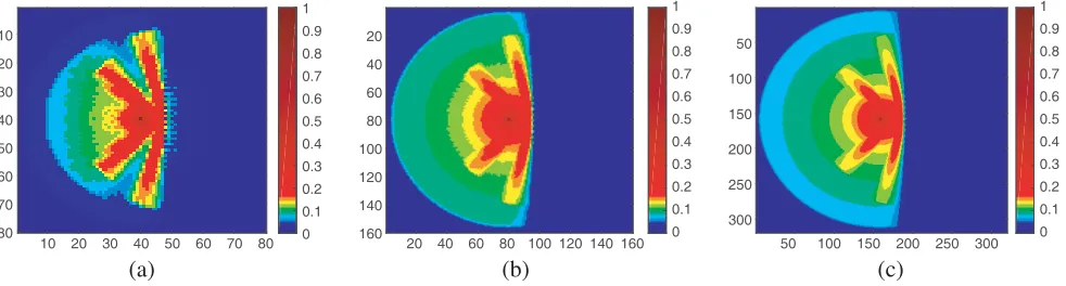
The field distribution around the plasma slab is obtained using NS-FDTD and standard FDTD method for different values of discretization parameter N. Figs. 2(a), (b), and (c) give the simulation results using NS-FDTD for taking values of N as 8, 16, and 32. Similar distribution patterns obtained using standard FDTD are depicted in Figs. 3(a), (b), and (c) for the same values of N. It is clear from Fig. 2(a) that even for a discretization value of 8, as shown by Cole [1] for NS-FDTD, we get all the sufficient information. Field distributions of the propagating field|Emax| are used for the visualization
of both the algorithms, and the obvious advantages of NS-FDTD method over the standard one in the accuracy of the range of 104 can be read from the data collected. The accuracy obtained in NS-FDTD forN = 8 is achievable only for standard FDTD withN = 1140 [1]. Since the required profile can be reconstructed in NS-FDTD with small values of N, the number of iterations needed is much less than that for the standard algorithm. In the case of metamaterials, the number of constituent structures like Split Ring Resonator (SRR) and conducting wires needed within one wavelength should exceeds a minimum number for homogeneity of the medium. To simulate such meta-structures, the needed task of discretization of each constituent structure will enormously enhance the computational domain
10 20 30 40 50 60 70 80
10 20 30 40 50 60 70 80 0 0.1 0.2 0.3 0.4 0.5 0.6 0.7 0.8 0.9 1
20 40 60 80 100 120 140 160 20 40 60 80 100 120 140 160 0 0.1 0.2 0.3 0.4 0.5 0.6 0.7 0.8 0.9 1
50 100 150 200 250 300
50 100 150 200 250 300 0 0.1 0.2 0.3 0.4 0.5 0.6 0.7 0.8 0.9 1
(a) (b) (c)
10 20 30 40 50 60 70 80 10
20
30
40
50
60
70
80 0
0.1 0.2 0.3 0.4 0.5 0.6 0.7 0.8 0.9 1
20 40 60 80 100 120 140 160 20
40
60
80
100
120
140
160 0
0.1 0.2 0.3 0.4 0.5 0.6 0.7 0.8 0.9 1
50 100 150 200 250 300
50
100
150
200
250
300
0 0.1 0.2 0.3 0.4 0.5 0.6 0.7 0.8 0.9 1
(a) (b) (c)
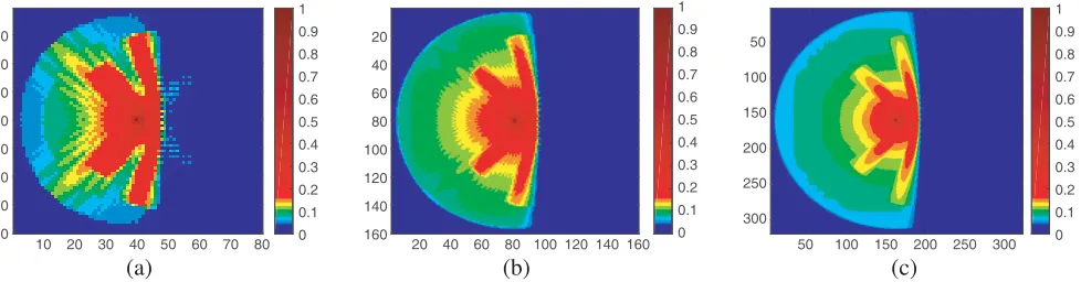
Figure 3. Electric field distribution near the wire medium when it interact with a sine wave using standard FDTD. (a)N = 8, (b)N = 16 and (c)N = 32.
dimension. In the case of standard FDTD, this will require a very large value ofN for getting a minimum accuracy where the same can be easily achieved by nonstandard algorithm for some minimum values of N.
5. CONCLUSION
The NS-FDTD algorithm is implemented for artificial negative permittivity medium, and the results are compared with the standard FDTD. The reflection mechanism from the medium is analyzed using a sine wave of frequency less than the plasma frequency. The advantages of NS-FDTD over the standard one are verified. This high accuracy and less time consuming nonstandard FDTD algorithm successfully applied for the first time in a medium with conducting wires in the form of an artificial plasma medium will pave the way for the introduction of this powerful technique to the regime of complicated meta-structures.
ACKNOWLEDGMENT
Jovia Jose gratefully acknowledges UGC of India for the financial support under FDP.
REFERENCES
1. Cole, J. B., “High accuracy solution of Maxwell’s equations using nonstandard finite differences,”
Computers in Physics, Vol. 11, No. 3, 287–292, 1997.
2. Cole, J. B., “Generalized nonstandard finite differences and physical applications,” Computers in Physics, Vol. 12, No. 1, 82–87, 1998.
3. Ohtani, T., K. Taguchi, T. Kashiwa, Y. Kanai, and J. B. Cole, “Nonstandard fdtd method for multifrequency analysis,” IEEE Transactions on Magnetics, Vol. 44, No. 6, 1390–1393, 2008. 4. Ohtani, T., K. Taguchi, T. Kashiwa, Y. Kanai, and J. B. Cole, “Nonstandard fdtd method for
wideband analysis,” IEEE Transactions on Antennas and Propagation, Vol. 57, No. 8, 2386–2396, 2009.
5. Ohtani, T., K. Murakami, K. Taguchi, and T. Kashiwa, “Complex nonstandard FDTD method for dispersive media,” 11th International Symposium on IEEE Antennas Technology and Applied Electromagnetics [ANTEM 2005], 1–4, 2005.
6. Jerez, S. and A. Lara, “A high resolution nonstandard fdtd method for the TM mode of Maxwell’s equations,” Mathematical and Computer Modelling, Vol. 54, Nos. 7–8, 1852–1857, 2011.
8. Cole, J. B., “High-accuracy FDTD solution of the absorbing wave equation, and conducting Maxwell’s equations based on a nonstandard finite-difference model,” IEEE Transactions on Antennas and Propagation, Vol. 52, No. 3, 725–729, 2004.