OPTICAL BANDPASS FILTER DESIGN USING SPLIT RING RESONATORS
A. Zarifkar
Optical Communication Group
Iran Telecommunication Research Center (ITRC) P. O. Box: 14155-3961, Tehran, Iran
A. Rahmani
Department of Electrical and Electronic Engineering Islamic Azad University
Research and Sciences Branch, Tehran, Iran
Abstract—Bandpass filter design using metallic split ring resonators (SRR) at optical frequencies is theoretically investigated in this paper. The transmission and reflection coefficients and the transmission phase of SRR array will be analyzed. We will show that there are many magnitude peaks in transmission coefficient that can be used as bandpass filter in 1550 nm-band. Increasing the number of SRR layers will cause increase in the number of magnitude peaks and narrowing of the bandwidth. The numerical analysis is performed using the transfer matrix method (TMM).
1. INTRODUCTION
Recently, optical properties of metamaterials have been considered theoretically and experimentally due to their potential applications
as negative index materials. The theory of the propagation of
electromagnetic waves in such media was developed more than three
decades ago by Veselago [1]. The main ideas, which led to the
fabrication of the first left-handed materials (LHM), were proposed by Pendry et al. [2–4]. This group claimed that a lattice of metallic split ring resonators (SRRs) with characteristic features in the millimeter range behaves as an effective medium with a negative magnetic
permeabilityµeff [2]. After Pendry’s work, Smith [5–7] made the array
as the negative µ material in microwave region. As far as we know,
this SRR array is the first negativeµmaterial. Recently, experimental
studies of magnetic properties of SRRs have been reported in the THz
region [8], particularly at 30 THz (10µm wavelength) [9], and 100 THz
(3µm wavelength) [10]. On the other hand, theoretical studies of SRR
behavior have been done from THz to near-infrared region [11, 12]. Arrays of SRRs in thin metallic films show great promise in a number of different fields, due to their high transmission efficiencies at resonant
wavelengths and strongly enhanced and localized optical fields. It
has been shown both computationally and experimentally that such metallic structures display excellent band-pass characteristics. Also, considering potential technological applications, it would be equally important to fabricate SRRs at optical frequencies.
Recently, the interest in this field moves to the optical and visible light ranges [13, 14]. Realization of metamaterials possessing properties of an artificial magnetic material in the visible range would allow realization of artificial materials with negative index of refraction and open a way for many novel applications. One of the possible routes is the use of nano-sized resonant metal particles of complex shapes. Various shapes have been proposed which their operational principles are basically the same. In particular, several variants of split rings have been manufactured and measured in frequency range of hundreds of terahertz and in the visible range [15, 16]. When assembling the metamaterials at THz or higher frequencies by scaling down the dimensions of the resonators, the major inconvenience that we face is the difficulty of the small-scale manufacturing process. However, it has been noticed that the geometrical scaling of the particle resonant frequency breaks down when the working frequency gets higher, so that the resonant frequency saturates at the level of several hundreds of terahertz [17, 18]. This effect is explained by the plasmonic behavior of metals at visible frequencies, usually in terms of kinetic energy of electrons carrying current and an additional electron self-inductance
[17]. Thus, numerical studies such as the present work can be a
guide for future experimental efforts aimed for fabrication of SRRs that operate at optical frequencies. There are several reasons why this extension cannot be done simply by scaling down the characteristic dimensions of the building blocks of SRR. First, as the frequency approaches the optical spectrum, the frequency dispersion of the
dielectric function of the metal becomes important. Secondly, as
investigated and shown that reducing the dimensions and using silver
for SRR are necessary to realize the negative µ and correct operation
of SRR in the optical and visible light ranges [14].
2. ANALYSIS
In the present work, we focus on transmission and reflection coefficients of a double SRR in optical frequency range, that is, wavelengths
between 1530 nm and 1570 nm (f = 191–196 THz). We will show that a
lattice of double SRRs can be used as an optical filter in this frequency range. The geometrical feature and equivalent circuit of the symmetric transmission line (TL) of double SRR unit-cell are presented in Fig. 1.
Here r is the inner radius of the ring,w is the width of the rings,dis
the distance between two rings,ais the unit-cell dimension in thexy
-plane, andlis the distance between adjacent planes of the SRRs along
the z-axis. Here we used related formula for SRR [22] and pendry’s
recipe [23] to derive geometrical capacitance and inductance. Also in contrast to the microwave regime, in the optical range, metals do not behave as ideal conductors, and addition to parallel-plate capacitance and conducting inductance, additional capacitances and inductances
of the rings should be considered (Cadd,Ladd) [24].
Figure 1. The geometrical feature and equivalent circuit model of the symmetric transmission line of double split ring resonator unit-cell.
In analyzing the transmission properties of a SRR slab, we used
transfer matrix method (TMM) [25]. A main advantage of using
TMM approach is that it allows one to decompose large structures, for which the transfer matrix might be difficult to calculate, into smaller ones which can be calculated easier. Subsequently, from these matrices which characterize the subdivision of the large structure, one can calculate the transfer matrix for the entire structure. The reason why this approach works is that the transfer matrix obeys the
multiplication rule (T12 = T2 ·T1), by which the transfer matrices of
two adjacent subdivisions (T1, T2) multiply together and result the
transfer matrix of the combined structure (T12). However, repeated
use of this procedure can lead to numerical instabilities. As one adds new layers, the numerical instabilities in the transfer matrix build up, leading to massive computational problems. To overcome this problem, and account for the combined effect of two layers of material, we used a similar procedure except that we constructed the scattering matrix of an ensemble of two layers from scattering matrices of each
layer. The advantage of this approach is that the elements of the
scattering matrix are of the order of unity; consequently, when applied to scattering matrices, this recursive process is numerically stable
[26–28]. The drawback is that computing of the scattering matrix
for two layers by using the scattering matrix of each layer require much computation. Therefore, in practice one can calculate first the transfer matrices for subsystems that are as large as possible; then determine the scattering matrices for these subsystems; and finally, from these scattering matrices, calculate the scattering matrix for the entire system.
In this case, the magnetic field of incident wave, is perpendicular to the SRRs plane and the propagation direction is along the plane and
N layers of SRRs. By adjusting the geometrical parameters, including
linewidth, radius, and the gap distance of the SRR structures, the resonance can be tuned to a specific frequency of interest. Also the
SRR dimensions are, a = 200 nm, r = 41.6 nm, w = δ = 20.5 nm,
d= 10 nm and l= 40 nm. There are some restrictions that should be
considered. One is that, the unit-cell dimension should be smaller than
incident wavelength (aλ). If this condition were not complied, there
would be the possibility that internal structure of the medium could diffract as well as refract radiation giving the game away immediately. Another restriction that is important, occurs during the decreasing
SRR dimensions for reaching the higher resonant frequency. This
resonance must be less than the plasma frequency which, is the
resonant frequency of electrons oscillation inside metal (ω < ωp). So we
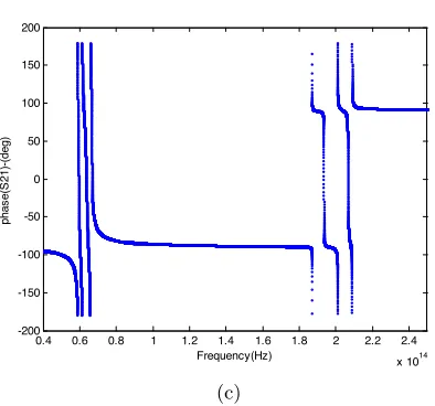
The transmission and reflection coefficient and the transmission
phase forN = 5 layers of SRRs are presented in Fig. 2. As this figure
shows, there is a gap in the transmission coefficient, which, being at
1.1×10¹⁴Hz. Also there are many magnitude peaks in the measured
transmission coefficient, which are essentially due to the impedance mismatching at the terminal ports. This mismatching is resulted from the wide variations in the frequency range of the incident wave and unbalanced condition of equivalent circuit of the SRR unit-cell. This condition occurs when the resonant frequencies of the shunt and serial capacitance and inductance in the equivalent circuit of transmission
line are not equal, that is ωse = ωsh or LL ·CR = LR ·CL. It
0.4 0.6 0.8 1 1.2 1.4 1.6 1.8 2 2.2 2.4
x 1014
-250 -200 -150 -100 -50 0 Frequency(Hz) T ra n s m is s io n Co e ff ic ie n t(S 2 1 )-(d B ) (a)
0.4 0.6 0.8 1 1.2 1.4 1.6 1.8 2 2.2 2.4
0.4 0.6 0.8 1 1.2 1.4 1.6 1.8 2 2.2 2.4 x 10¹⁴ -200
-150 -100 -50 0 50 100 150 200
Frequency(Hz)
phas
e(S
21)-(deg)
(c)
Figure 2. Transmission coefficient (a), reflection coefficient (b), and
phase of S21 (c) forN = 5 layers of SRR.
is noteworthy that the magnitude peaks exactly correspond to the resonance modes of the N-cell Resonators, which exist when the phase isφ= 0, π,−π,−2π, . . ..
We show that one can use each of these magnitude peaks as an optical bandpass filter. The magnitude of the transmission and reflection coefficients and the transmission phase for one of these peaks
forN = 5 layers of SRR are presented in Fig. 3.
As we see, this peak is located at 1550 nm-band, and the −3 dB
1.91 1.915 1.92 1.925 1.93 1.935 1.94 1.945 1.95 1.955 1.96 x 10¹⁴ -40
-35 -30 -25 -20 -15 -10 -5 0 5
Frequency(Hz)
T
ra
n
s
m
is
s
io
n
Co
e
ff
ic
ie
n
t(S
2
1
)-(d
B
)
1.91 1.915 1.92 1.925 1.93 1.935 1.94 1.945 1.95 1.955 1.96
x 1014
-40 -35 -30 -25 -20 -15 -10 -5 0 5
Frequency(Hz)
Re
fl
e
c
ti
o
n
Co
e
ff
ic
ie
n
t(S
1
1
)-(d
B
)
(b)
1.91 1.915 1.92 1.925 1.93 1.935 1.94 1.945 1.95 1.955 1.96
x 1014
-200 -150 -100 -50 0 50 100 150 200
Frequency(Hz)
phas
e(S
21)-(deg)
(c)
Figure 3. Transmission coefficient (a), reflection coefficient (b), and
phase of S21 (c) for N = 5 layers of SRR, for one of the magnitude
peaks at 1550 nm-band.
bandwidth of this bandpass filter is 100 GHz. If we want to have a filter with narrower bandwidth less than 100 GHz, we should use many
more SRR layers. The related figures for a magnitude peak forN = 10
layers of SRR are presented in Fig. 4.
peaks, one can reduce the bandwidth of the filter.
However, there is a limitation to the number of peaks and it may that some adjacent peaks add to the 1550 nm-band. The other
important parameter of this filter is central resonance frequency (f0)
which depends on the dimensions of SRRs and by changing the
dimensions, f0 is tuned to the selected frequency. As we see, this
central resonance frequency is located at 193.3 THz.
1.91 1.915 1.92 1.925 1.93 1.935 1.94 1.945 1.95 1.955 1.96
x 1014
-40 -35 -30 -25 -20 -15 -10 -5 0 5 Frequency(Hz) T ra n s m is s io n C o e ff ic ie n t(S 2 1 )-(d B ) (a)
1.91 1.915 1.92 1.925 1.93 1.935 1.94 1.945 1.95 1.955 1.96
x 1014
1.91 1.915 1.92 1.925 1.93 1.935 1.94 1.945 1.95 1.955 1.96
x 1014
-200 -150 -100 -50 0 50 100 150 200
Frequency(Hz)
phas
e(S
21)-(deg)
(c)
Figure 4. Transmission coefficient (a), reflection coefficient (b), and
phase of S21 (c) for N = 10 layers of SRR, for one of the magnitude
peaks at 1550 nm-band.
3. CONCLUSION
We demonstrated that the array of silver SRRs can be used as a
bandpass filter at optical frequencies in the 1550 nm-band. The
transmission and reflection coefficients and the transmission phase of SRR array were analyzed and it is shown that there are many magnitude peaks in transmission coefficient of these SRR arrays which enable us to use them as bandpass filters with acceptable bandwidths. Increasing the number of resonant peaks by adding the number of SRR layers can be a useful way to narrow the filter bandwidth. Also this filter is tunable to the selected frequency by changing the dimensions of the SRR. Although, the dimension required for producing this effect can be challenging for most nanofabrication tools, they are still within the capability of state-of-the-art technology.
REFERENCES
1. Veselago, V. G.,Usp. Fiz. Nauk, Vol. 92, 517, 1964.
2. Pendry, J. B., A. J. Holden, D. J. Robbins, and W. J. Stewart,
IEEE Trans. Microwave Theory Tech., Vol. 47, 2075, 1999.
3. Pendry, J. B., A. J. Holden, W. J. Stewart, and I. Youngs,Phys.
4. Pendry, J. B., A. J. Holden, D. J. Robbins, and W. J. Stewart,J. Phys.: Condense. Matter, Vol. 10, 4785, 1998.
5. Smith, D. R., W. J. Padilla, D. C. Vier, S. C. Nemat-Nasser, and
S. Schultz, Phys. Rev. Lett., Vol. 84, 4184, 2000.
6. Shelby, R. A., D. R. Smith, S. C. Nemat-Nasser, and S. Schultz,
Appl. Phys. Lett., Vol. 78, 489, 2001.
7. Shelby, R. A., D. R. Smith, and S. Shultz, Science, Vol. 292, 77,
2001.
8. Yen, T. J., W. J. Padilla, N. Fang, D. C. Vier, D. R. Smith,
J. B. Pendry, D. N. Basov, and X. Zhang,Science, Vol. 303, 1494,
2004.
9. Hsu, A.-C., Y.-K. Cheng, K.-H. Chen, J.- L. Chern, S.-C. Wu,
C.-F. Chen, H. Chang, Y.-H. Lien, and J.-T. Shy, Jpn. J. Appl.
Phys., Vol. 43, L176, 2004.
10. Linden, S., C. Enkrich, M. Wegener, J. Zhou, T. Koschny, and
C. M. Soukoulis,Science, Vol. 306, 1351, 2004.
11. Panoiu, N.-C. and R. M. Osgood, Jr., Phys. Rev. E, Vol. 68,
016611, 2003.
12. O’Brien, S. and J. B. Pendry,J. Phys. Condens. Matter, Vol. 14,
6383, 2002.
13. Panoiu, N. C. and R. M. Osgood, Jr., Science, Opt. Commun.,
Vol. 223, 331–337, 2003.
14. Ishikawa, A. and T. Tanaka, Science, Opt. Commun., Vol. 258,
300–305, 2006.
15. Moser, H. O., B. D. F. Casse, O. Wilhelmi, and B. T. Saw,Phys.
Rev. Lett., Vol. 94, 063901, 2005.
16. Katsarakis, N., G. Konstantinidis, A. Kostopoulos, R. S. Penciu, T. F. Gundogdu, M. Kafesaki, E. N. Economou, T. Koschny, and
C. M. Soukoulis,Optic Lett., Vol. 30, 1348–1350, 2005.
17. Zhou, J., T. Koschny, M. Kafesaki, E. N. Economou, J. B. Pendry,
and C. M. Soukoulis,Phys. Rev. Lett., Vol. 95, 223902, 2005.
18. Klein, M. W., et al., Optics Lett., Vol. 31, 1259–1261, 2006.
19. Ebbesen, T. W., H. J. Lezec, H. F. Ghaemi, T. Thio, and
P. A. Wolff, Nature, Vol. 391, 667, 1998.
20. Lezec, H. J., A. Degiron, E. Devaux, R. A. Linke, L.
Martin-Moreno, F. J. Garcia-Vidal, and T. W. Ebbesen,Science, Vol. 297,
820, 2002.
21. Chen, C. J. and R. M. Osgood, Phys. Rev. Lett., Vol. 50, 1705,
1983.
and Slotlines, second ed., Artech House, Boston, 1996.
23. Pendry, J. B., A. J. Holden, D. J. Robbins, and W. J. Stewart,
IEEE Trans. Microwave Theor. Tech., Vol. 47, 2075, 1999.
24. Tretyakov, S.,Science, Metamat., Vol. 1, 40–43, 2007.
25. Caloz, C. and T. Itoh,Electromagnetic Metamaterials:
Transmis-sion Line Theory and Microwave Applications, J. Wiley, 2006.
26. Pendry, J. B. and A. MacKinnon,Phys. Rev. Lett., Vol. 69, 2772,
1992.
27. Pendry, J. B.,J. Mod. Opt., Vol. 41, 209, 1994.
28. Bell, P. M., J. B. Pendry, L. M. Moreno, and A. J. Ward,Comput.