Improving Automatic Generation Control a Two-Area Power
System Using FOPID with Harmony Search Algorithm
D.Reddi Rani & K.Raju
1
PG Student, Dept of Electrical and Electronics Engineering, ChadalawadaRamanamma
Engineering College, Tirupati, A.P, India
2
Assistant Professor, Dept of Electrical and Electronics Engineering,
ChadalawadaRamanamma Engineering College, Tirupati, A.P, India
E-mail:
[email protected]
&
[email protected]
ABSTRACT--This paper presentsanAutomatic Generation Control (AGC) system in a two-area power system with a fractional order PID (FOPID) controller. In the proposed method, a newly developed harmony search algorithm is implemented to solve the non-convex non-linear problem of AGC. The fractional order PID controller will improve the system stability and improve the robustness of the controlled system. The proposed FOPID controller also has a smaller number of parameters to tune than its existing counterparts.In order to show efficiency of the proposed approach, the response of HSA-Optimized system to disturbances is compared with the results of GA-Optimized system. The cost function of the proposed problem is considered based on Integral of Time Multiplied Square Error (ITSE). In order to improve the system performance, frequency bias factor (FBF) is modeled in the problem and the proposed method is implemented in a non-linear interconnected two area power system. Simulation results verified that employing the proposed approach in optimization process of control system would guarantee a better system performance comparing to other methods.
Keywords- Integral of Time Multiplied Square Error; Harmony Search Algorithm; two-area nonlinear power system; Load- Frequency Control.
I.INTRODUCTION
Day to day theload demand is growingatvery high rate. Due to surplus demand of electricity with increase inpopulation and industrialization, the power generation withconventional sources was a great challenge to the generationstations to fulfill the demands.So, modern human societies have increased the significance of optimum Automatic Generation Control (AGC). By overlooking a well-designed AGC, the electric power system will face a lot of complicated difficulties. In
other words, in an optimal operation of power system, it is indispensable that frequency deviations must maintain in allowable limits by a well-designed AGC [1].
Manypapers have been published on the AGC problem considering a linear model. In [2], AGC is employed by utilizing linear feedback. Optimal control and neural network-based controller are some other methods employed in the AGC of a linear power system [3]. Additionally, some extra papers have been published on controlling non-linear model of the governor, generator and power system [5-7]. These methods are significantly time-inefficient in the AGC of power system.
Regardless of all the developments in control methods, fractional order Proportional-Integral-Derivative (FOPID) controllers are still the most common type of controllers in industries. Therefore, it is sensible that a lot of papers have been published in these years on adjusting FOPID controller parameters using optimization algorithms [8-10]. There are different criteria employed in these papers to evaluate effectiveness of the enhanced controllers. Some papers have working an Integral of Absolute Error of system response to a step demand change [11-12], and some others have used an Integral of Square Error to the same disturbance [11]. Integral of Time Multiplied Square Error [12-13] and Integral of Time multiplied Absolute Error are other criteria implemented in published papers.
In this paper, a new method is labeled to resolve AGC problem of an interconnected two-area non-linear power system by droppingthe system frequency deviances. In order to overwhelm the convex non-linear nature of the AGC problem, aenhanced harmony search algorithm (HSA) is employed to solve the problem.
criterion as long as these conditions by weighting error over time duration [12]. In addition, an Area Control Error (ACE) is definite and designed in accordance with the similar area feedback. Thus, a control procedure to set the ACE value to zero is employed in the scheme. As a result, the frequency and power interchange between areas will be fixed on anticipated values. On the other hand, a Frequency Bias Factor (FBF) is considered for each area to guarantee a proper ratio between frequency error and tie-line power error.
II. SINGLE MACHINE POWER SYSTEM
The linearized model of single-machine power system which is used for the dynamic studies of this paper is demonstrated in Fig. 1 [8, 10]. In this figure,
Ris the regulator slope. Turbine and governor transfer function can be written as:
Figure 1. Diagram of load-frequency control system in a single-machine power system
Where TG and TT are the governor and turbine time constants, respectively. Furthermore, the transfer function considered for PID controller and power system can be written as:
Where H , M = 2H / f and D are the generator inertia constant, inertia constant and damping factor, respectively. Therefore, state space equations of the system demonstrated in Fig. 1 is as follows:
In this paper, a low-pass-filter is added to the input of derivative controller to cancel the high-frequency noise. Therefore, the transfer function for derivative part of PID controller can be written as:
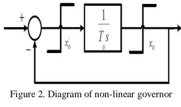
In addition, a more detailed nonlinear model of the governor is employed in this paper. As shown in Fig. 2, the governor has been modeled with the upper and lower limits.
Figure 2. Diagram of non-linear governor
III.PARAMETERS OF THE SYSTEM AND DESIGNED CONTROLLER
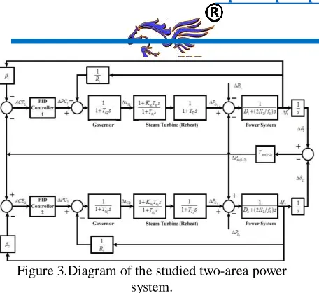
In this paper, an interconnected two-area nonlinear model of power system has been studied. The system diagram considering AGC and the controller is given in Fig. 3 [8, 14, and 15]. A PID controller which is optimized by Harmony Search Algorithm is employed to handle automatic generation
Figure 3.Diagram of the studied two-area power system.
and tie-line power control. Defining ACE signal according to Fig. 3, PID controller equation in AGC can be expressed as:
IV. PROPOSED HARMONY SEARCH ALGORITHM
Harmony search algorithm is a newly developed metaheuristic optimization algorithm based on music improvisation. In this algorithm, the instrumentalists will start playing their instruments step-by-step, in order to achieve pitch adjustment and improving harmony. All steps of harmony search algorithm are demonstrated in Fig. 4 and are described in following paragraphs.
Where KP,i
,
KI,iand KD,iare the proportional, integral and derivative coefficients of itharea, respectively. On theother hand, I β represents the frequency bias factor for itharea. ITAE criterion is calculated by (9), utilizing
frequency deviations of each area and tie-line power deviations.
The 2nd and 3rd parts of (9) are the cost functions which guarantee that optimized PID controller will maintain the speed and displacement of governor within the limits. Therefore,
ε
1andε
2are selected so thatand will be much
greater than ITAE in saturation and will be zero in
optimum point [8, 11 and 14].
e
1ande
2represent thesaturation-limit outage level for the governor and can be written as:
Where and
are maximum allowed governor speed, maximum calculated governor speed, maximum allowed governor displacement and maximum calculated governor displacement, respectively.
Figure 4. Flowchart of Harmony Search Algorithm
A. Problem definition and initializing parameters of algorithm
The optimization problem is defined as follows:
Which f (x) is the objective function, hv(x) and gu(x) are equality and inequality constraints, x is a set of decision variables and X is the set of possible values for decision variables. On the other hand, xiL≤ xi≤ xiUcan guarantee that each decision variable will maintain between
xiLandxiUwhich are the lower and upper limits of each decision variable. HSA parameters which are the Number of Solution Vectors in HM (HMS), HM
Considering Rate (HMCR), Pitch Adjusting
Rate (PAR) and Number of Solution Vector Generations (NI), are set in this step.
HM is a memory which all feasible solution vectors are saved there. In other words, HM is an equivalent to the genetic pool in Genetic Algorithm. HMCR and PAR are the parameters utilized in order to achieve the best answer in step 3 of the optimization algorithm.
B. Initializing harmony memory
Therefore, the number of saved solution vectors in HM is determined by HMS. In the next steps, new solutions are generated and HM will be updated.
C. Generating a new harmony using improvisation
A new solution vector is
generated based on memory considerations, pitch adjustment and random selection which is called improvisation. The 1st decision variable of new vector is selected in the allowed interval, which is
. HMCR represents the probability of selecting a previously saved value in HM; therefore (1− HMCR) is the probability of random generation of decision variables.
As an example, HMCR=0.9 means that the possibility of selecting the decision variable from the previously saved solutions is 90%; while generating a new solution in the feasible interval is 10% probable. Each part obtained by memory considerations will be tested for pitch adjustment evaluation. This step is implemented using PAR parameter. Pitch adjustment rate is defined as:
(1-PAR) is the probability of being unchanged. If the decision for pitch adjustment is YES, x'i will be
replaced as:
Wherebw is the audible sound bandwidth and rand, () is a random number in (0, 1) interval. In step 3, memory considerations, pitch adjustment and random selection are applied to each variable of harmony vector.
D. Harmony search algorithm improvement
In order to improve the harmony search algorithm, a newly developed HSA, based on Non-fixed PAR and bw value is presented in [18]. In this paper, PAR value is dynamically adjusted in each generation:
Where PAR is pitch adjustment rate in each iteration,
PAR minand PAR maxare minimum and maximum limits
of PAR value and g is the iteration number. Furthermore, bwis also dynamically adjusted in each iteration:
wherebw(g) , min bw and max bw are audible bandwidth in each iteration, minimum and maximum bounds of audible bandwidth.
E. Updating harmony memory
In this step, if the new harmony vector is better than the worst harmony vector saved in HM, it will be added to HM and the worst vector will be deleted.
F. Check for convergence
In this step, if the stop criterion of the algorithm (maximum number of improvisations) is satisfied, the calculations will be terminated and otherwise, steps 3 and 4 will be repeated till satisfying the criterion.
V. SIMULATION AND RESULTS
In this section, different scenarios are utilized to show the effectiveness of proposed method tso optimize the PID controller parameters. The time-domain simulations are executed for 60 seconds using MATLAB 7.6. Parameters of the studied interconnected two-area non-linear power system and the proposed harmony search algorithm for PID controller optimization are given in Table I and Table II, respectively. In each step of the optimization, parameters of Table II are updated using the proposed method in order to achieve a better answer.
Furthermore, the response of system while using GA optimized PID controller is compared with the proposed HAS optimized one. GA parameters comprising the number of generations, population, crossover and mutation probability are 100, 100, 0.9 and 0.01, respectively.
A. First Scenario: Disturbance ( PL1) in the Area 1
In this section, a step load increase has been applied to the area 1 ( PL1) at the rate of 1% in terms of p.u. The
system response while utilizing FBF in optimization process and the results of ignoring it is given as the deviation of frequency in area 1 and area 2 ( f1 and f2 )
and the change of tie-line power ( Ptie(1 2)− )in Fig. 5 and
it is clear that the HSA-optimized system has less fluctuation and a smaller settling time in comparison with GA-optimized system.
TABLE I. PARAMETERS OF THE STUDIED POWER SYSTEM
TABLE II.PARAMETERS OF HARMONY SEARCH ALGORITHM
Therefore, frequency and tie-line power deviations in presence of the optimized PID controller based on harmony search algorithm has more speed toward zero in comparison with GA-optimized controller, and thus, it can be utilized as a well-designed controller to provide the desired damping of frequency and tie-line power oscillations. As shown in Fig. 5, it is clear that comprising FBF in optimization process can improve accuracy and speed of system response to disturbances. Additionally, numerical values of the error criterion (ITAE) are listed in Table III. It is clear that utilizing the proposed method considering FBF, can improve the system accuracy, speed and usefulness.
Fig Simulink model for Self Tuning PID with GA of the Two Area Test System
Fig Simulink model for Self Tuning FOPID with HSA of the Two Area Test System
TABLE IV. ITAE ERROR CRITERION
CONCLUSIONS
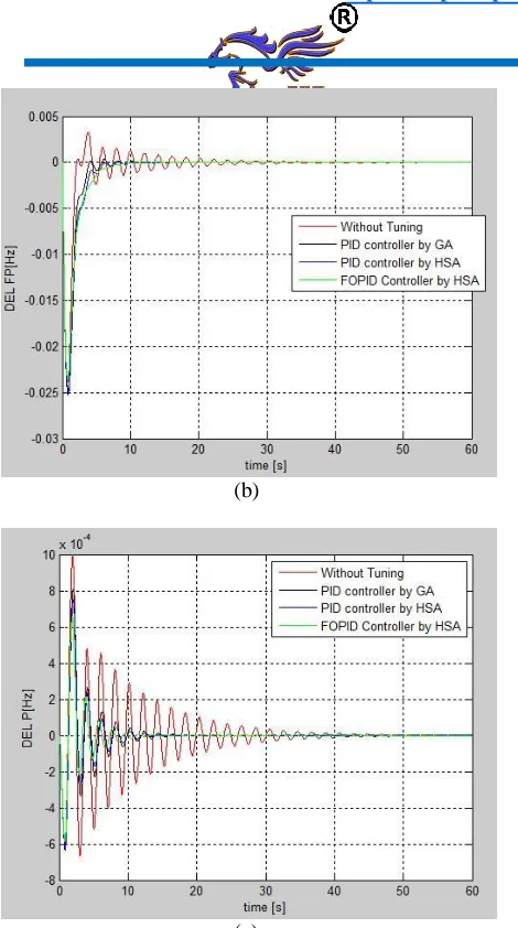
(b)
(c)
Figure 5. (a) Frequency deviation in area 1(Δf1), (b) frequency deviation in area 2 (Δf2), and (c) the tie-line
power between two areas ( Ptie).
TABLE III.ITAE ERROR CRITERION
In order to study simultaneous disturbances in a two-area nonlinear interconnected power system, a step load
increase has been applied simultaneously to area 1 (
PL1) and area 2 ( PL2) at the rate of 1% in terms ofp.u.
Simulation results while utilizing FBF in optimization process is given as the deviation of frequency in area 1 and area 2 ( f1 and f2 ) and the
change of tie-line power ( Ptie(1 2) − ) in Fig. 7.
In this paper, a new method for optimum adjustment of a FOPID controller of automatic generation control in an interconnected two-area non-linear power system is studied. In this method, a newly developed optimization algorithm called HSA is implemented for minimizing the cost function of problem which is based on ITAE. Furthermore, in order to improve system response to disturbances, the frequency bias factor is applied to the optimization problem. According to the results of the system while using the optimized PID-controller, it is proven that HSA will result in a better solution in less time, comparing to GA. It also has been proven that applying the frequency bias factor to optimization process will result in a better system performance. Finally, it can be concluded that the proposed method shows a better performance comparing to other similar methods.
REFERENCES
[1] Kundur, P., (1994) Power system stability and control. McGrawíhill,.
[2] Kocaarslan, I., Cam, E., (2005) “Fuzzy logic controller in interconnected electrical power systems for loadífrequency control,” Int. J. of Electrical Power & Energy Systems, Vol. 27, pp. 542í549.
[3] Ghazal, M., Poshtan, J., Poshtan M., (2010) “Application of LQG\LTR method in load frequency control,” Int. Review of Electrical Engineering, Vol. 5, pp. 2809í2818.
[4] Yesil, E., Guzelkaya, M., Eksin, I., (2004) “Self tuning fuzzy PID type load and frequency controller,” Int. J. of Energy Conversion and
Management Vol. 45, pp. 377–390.
[6] Lee, H.J., Park, J.B., Joo, Y.H., (2006) “Robust load-frequency control for uncertain nonlinear power systems: A fuzzy logic approach,” Information Sciences, Vol. 176, pp. 3520–3537.
[7] Bevrani, H., Hiyama, T., (2008) “Robust decentralized PI based LFC design for time delay power systems,” Int. J. of Energy Conversion and Management, Vol. 49, pp.193–204.
[8] Gaing, Z.L., (2004) “A Particle Swarm Optimization Approach for Optimum Design of PID Controller,” IEEE Trans. on Energy Conversion, Vol. 19, pp. 384í391.
[9] Krohling, R.A., Rey, J. P., (2001) “Design of Optimal Disturbance Rejection PID Controllers using Genetic Algorithm,” IEEE Trans. on Evolutionary Computation, Vol. 5, pp. 78–82.
[10] Visioli, A., (2001) “Tuning of PID Controllers with Fuzzy Logic,” Proc. Inst. Elect. Eng. Contr. Theory Applications, vol. 148, pp. 1–8.
[11] Shayeghi, H., Jalili, A., Shayanfar, H.A., (2008) “Multi-stage fuzzy load frequency control using PSO,” Int. J. of Energy Conversion and Management, Vol. 49, pp. 2570í2580.
[12] Abdel-Magid, Y.L., Dawoud, M.M., (1995) “Genetic algorithms applications in load Frequency Control,” Genetic Algorithms in Eng. Sys. Innovations and Applications, Conf. Pub.No.414, IEEE.
D.Reddi Rani iscurrentlypursuing her M.Tech (E.E.E) Power systems domain in S.V. college of engineering, Tirupati. She completed her B.Tech from Yogananda Institute of Technology and Science, Tirupati.