The Stream Cipher Core of the 3GPP
Encryption Standard 128-EEA3: Timing Attacks
and Countermeasures
⋆Gautham Sekar
Indian Statistical Institute, Chennai Centre,
SETS Campus, MGR Knowledge City, CIT Campus, Taramani, Chennai 600113, India.
Abstract. The core of the 3rdGeneration Partnership Project (3GPP) encryption standard 128-EEA3 is a stream cipher called ZUC. It was designed by the Chinese Academy of Sciences and proposed for inclusion in the cellular wireless standards called “Long Term Evolution” or “4G”. The LFSR-based cipher uses a 128-bit key. In this paper, we first show timing attacks on ZUC that can recover, with about 71.43% success rate, (i)one bit of the secret key immediately, and(ii)information involving 6 other key bits. The time, memory and data requirements of the attacks are negligible. While we see potential improvements to the attacks, we also suggest countermeasures.
Keywords:Stream cipher, cache timing attack, key recovery.
1
Introduction
ZUC [8] is a stream cipher designed by the Data Assurance and Communication Security Research Center (DACAS) of the Chinese Academy of Sciences. The cipher forms the core of the 3GPP mobile standards 128-EEA3 (for encryption) and 128-EIA3 (for message integrity) [7]. It was proposed for inclusion in the Long Term Evolution (LTE) or the 4th generation of cellular wireless standards (4G).1 ZUC is LFSR-based and uses a 128-bit key and a 128-bit initialization vector (IV). Some key points in the evolution of ZUC are listed in the following timeline.
Timeline:
⋆A shorter and older version of this paper appears in the proceedings of Inscrypt 2011. It was written when the author was with the National University of Singapore. 1 Strictly speaking, LTE is not 4G as it does not fully comply with the International
– 18th June 2010: The Security Algorithms Group of Experts (SAGE) of the European Telecommunications Standards Institute (ETSI) published a doc-ument providing the specifications of the first version of ZUC. The docdoc-ument was indexed “Version 1.0”.
– 26th–30th July 2010:Improvements and minor corrections were made succes-sively to the C implementation of the ZUC algorithm of Version 1.0. These resulted in versions 1.2 and 1.3 of the ETSI/SAGE document. The preface to Version 1.3 was corrected and the resulting document released as Version 1.4.
– 02nd–03rdDecember 2010 (First International Workshop on ZUC Algorithm): A few observations on the algorithm of Version 1.4 were reported (see [6]) but none of these posed any immediate threat to its security.
– 05th–09th December 2010 (ASIACRYPT): The algorithm of Version 1.4 was cryptanalysed by Wuet al. [24] and the results were presented at the rump session of ASIACRYPT 2010.
The attack reduces the effective key size of ZUC to about 66 bits by exploiting the fact that a difference set between a pair ofIVs may result in identical keystreams.
– 08th December 2010: Gilbertet al.reported an existential forgery attack on the 128-EIA3 MAC algorithm.
The attack allows, given any message and its MAC value under an un-known integrity key and an initialization vector, to predict the MAC value of a related message under the same key and the same initialization vector with a success probability of 1/2.
Gilbertet al. also gave a modified version of the 128-EIA3 algorithm (cf.
[12, Algorithm 2]).
In the original 128-EIA3 construction, some 32-bit keystream words are used in computing the universal hash function, and then the next whole word of keystream is used as a mask. But in [12, Algorithm 2], the first keystream word is used as the mask. The latter algorithm better fits the standard Carter-Wegman construction [5].
– 04th January 2011: In response to Wuet al.’s key recovery attack, the ini-tialization of ZUC was modified. Version 1.5 contains the new algorithm [8]. This algorithm is the one we analyse in this paper; we have been and shall henceforth be simply calling it “ZUC” (i.e., without any accompanying version numbers).
– 05th–06th June 2011 (The 2nd International Workshop on ZUC Algorithm
and Related Topics): Gilbert et al. presented an updated version (cf. [12]) of their paper. In this they argue that [12, Algorithm 2] might have slightly greater resistance against nonce reuse.
– 07th June 2011 –26th August 2011: Changing the ZUC integrity algorithm of 128-EIA3 to [12, Algorithm 2] was being considered by the ETSI/SAGE in June 2011. Although [12, Algorithm 2] offers some advantages, they appear to be marginal.
of the key immediately, and (ii) information involving 6 other bits of the key. Before describing how this paper is organised, we shall discuss timing attacks briefly.
Timing attack:This is a side-channel attack in which the attacker exploits tim-ing measurements of (parts of) the cryptographic algorithm’s implementation. For example, in the case of unprotected AES implementations based on lookup tables, the dependence of the lookup time on the table index can be exploited to speed up key recovery [4]. A cache timing attack is a type of timing attack which is based on the idea that the adversary can observe the cache accesses of a legitimate party. The cache is an intermediate memory between the CPU and the RAM and is used to store frequently used data fetched from the RAM. The problem with the cache memory is that, unlike the RAM, it is shared among users sharing a CPU.2 Hence, if Bob and Eve are sharing a CPU and Eve is aware that Bob is about to encrypt, Eve may initiate her cache timing attack as follows. She first fills the cache memory with values of her choice and waits for Bob to run the encryption algorithm. She then measures the time taken to load the earlier cache elements into the CPU; loading is quick if the element is still in cache (such an event is called acache hit; its complement is acache miss) and not overwritten by one of Bob’s values. This technique is known asPrime+Probe
[18]. Cache timing attacks have been successfully mounted on several ciphers, notably the AES [4, 18, 26, 14].
In [18], two types of cache timing attacks are introduced –synchronous and
asynchronous. In a synchronous attack, the adversary can make cache measure-ments only after certain operations of the cipher (e.g., a full update of a stream cipher’s internal state) have been performed. In this attack scenario, the plaintext or the ciphertext is assumed to be available to the adversary. An asynchronous cache adversary, on the other hand, is able to make cache measurements in par-allel to the execution of the routine. She is able to obtain a list of all cache accesses made in chronological order [26]. Here, there are different viewpoints on the resources available to the adversary. According to Osviket al., the adver-sary has only the distribution of the plaintext/ciphertext and not sample values [18]. Zenner differs in [26] where he argues that the adversary can (partially) control input/output data and observe cache behaviour. Asynchronous attacks are particularly effective on processors with simultaneous multithreading. One of the timing attacks in this paper is an asynchronous cache timing attack, and the other is a straightforward timing attack that does not involve the cache.
attacks and find that the proposed design modifications resist these improved attacks too. In addition, we see several highlights of our attacks such as the novelty of an employed technique. The paper concludes with a suggestion for future work, in the same section.
2
Specifications of ZUC
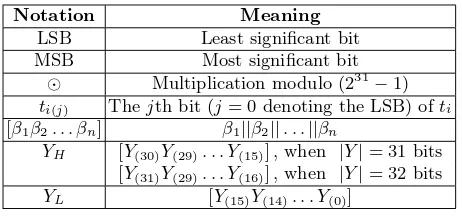
In this paper, we use several of the notation and convention followed in [8] in addition to that provided in Table 1.
Table 1.Notation and convention
Notation Meaning
LSB Least significant bit
MSB Most significant bit
⊙ Multiplication modulo (231−1)
ti(j) Thejth bit (j= 0 denoting the LSB) ofti [β1β2. . . βn] β1||β2||. . .||βn
YH [Y(30)Y(29). . . Y(15)] , when |Y|= 31 bits [Y(31)Y(29). . . Y(16)] , when |Y|= 32 bits
YL [Y(15)Y(14). . . Y(0)]
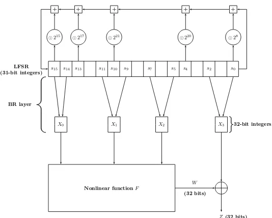
As previously mentioned, the inputs to the ZUC cipher are a 128-bit key and a 128-bitIV. The algorithm has three parts or “layers” – a linear feedback shift register (LFSR) layer, a bit-reorganisation (“BR”) layer and a nonlinear func-tionF. – that are shown in Figure 1. The execution of the algorithm proceeds in two stages – an initialization stage and a “working” stage. Each iteration of the algorithm in the working stage generates 32 bits of keystream output. We shall now detail the layers and stages to the level that is required for the under-standing of the results to follow. For the complete specifications, the interested reader is referred to [8, Sect. 3].
The LFSR layer: ZUC uses one LFSR that contains sixteen 32-bit cells con-taining 31-bit values s0, s1, . . . , s15. However, none of the 31-bit elements can assume the value 0; the remaining 231−1 values are allowed. The steps of the LFSR layer in the initialization mode comprise Algorithm 1.
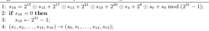
The steps of the LFSR layer in the working mode comprise Algorithm 2.
s15 s14 s13 s11 s10 s9 s7 s5 s4 s2 s0
Nonlinear functionF
X0 X1 X2 X3
BR layer
32-bit integers LFSR
(31-bit integers)
W
(32 bits)
Z(32 bits)
⊙215 ⊙217 ⊙221 ⊙220 ⊙28
+ + + + +
Fig. 1.The three layers of the ZUC algorithm
Algorithm 1The LFSR layer in the initialization mode 1: v:= 215⊙s
15+ 217⊙s13+ 221⊙s10+ 220⊙s4+ 28⊙s0+s0mod (231−1); 2: s16:= (v+u) mod (231−1); /*uis derived from the output ofF */ 3: if s16= 0then
4: s16←231−1;
5: (s1, s2, . . . , s15, s16)→(s0, s1, . . . , s14, s15);
The nonlinear function F:This function involves two 32-bit values in mem-ory cells (R1,R2), one 32×32 S-box (S), two linear transforms (L1,L2) and the aforementioned three 32-bit words produced by the BR layer. The output of the function F is a 32-bit wordW. The 32-bit keystream word Z, that is produced in every iteration of the working mode of the ZUC algorithm, is simplyW⊕X3. TheF function is defined as follows:
F(X0, X1, X2){
1: W = (X0⊕R1) +R2mod 232; 2: W1:=R1⊕X1;
3: W2:=R2⊕X2;
Algorithm 2The LFSR layer in the working mode
1: s16= 215⊙s15+ 217⊙s13+ 221⊙s10+ 220⊙s4+ 28⊙s0+s0mod (231−1); 2: if s16= 0then
3: s16←231−1;
4: (s1, s2, . . . , s15, s16)→(s0, s1, . . . , s14, s15);
Key loading:The key loading procedure expands the 128-bit secret key and the 128-bitIVto form the initial state of the LFSR. In [8], this key is denoted ask(= k0||k1||. . .||k15, where eachkiis a byte) and the IV as iv (=iv0||iv1||. . .||iv15, where each ivi is a byte). In addition to k and iv, a 240-bit constant D (= d0||d1||. . .||d15) is used in the key loading procedure. We shall now provide the binary representations of thedi’s first (in Table 2), followed by the key loading procedure.
Table 2.The constantsdi,i∈ {0,1, . . . ,15}, used in the key loading procedure
d0 100010011010111 d8 100110101111000
d1 010011010111100 d9 010111100010011
d2 110001001101011d10 110101111000100
d3 001001101011110d11 001101011110001
d4 101011110001001d12 101111000100110
d5 011010111100010d13 011110001001101
d6 111000100110101d14 111100010011010
d7 000100110101111d15 100011110101100
Given this, the key loading is a set of very simple and straightforward steps given by:
si=ki||di||ivi, fori∈ {0,1, . . . ,15}. (1)
The execution of ZUC: As mentioned earlier, the execution of the ZUC al-gorithm proceeds in two stages. We shall now describe these stages.
The initialization stage: This stage is given by Algorithm 3.
The working stage: This stage, in turn, has two sub-stages that are given by Algorithms 4 and 5.
3
Motivational Observations
Algorithm 3The initialization stage of ZUC execution 1: ctr= 0;
2: repeat
3: Execute theBRlayer;
4: Compute the nonlinear functionF taking as inputs the outputsX0,X1 andX2 of the BR layer;
5: Run Algorithm 1; 6: ctr←ctr+ 1; 7: untilctr = 32
Algorithm 4First sub-stage of the working stage of ZUC execution 1: Execute theBRlayer;
2: Compute the nonlinear functionF taking as inputs the outputsX0,X1andX2 of the BR layer;
3: Discard the outputW ofF; 4: Run Algorithm 2;
Algorithm 5 Keystream generating sub-stage of the working stage of ZUC execution
1: repeat
2: Execute theBRlayer;
3: Compute the nonlinear functionF taking as inputs the outputsX0,X1 andX2 of the BR layer;
4: Compute the keystream asZ=W⊕X3; 5: Run Algorithm 2;
Observation 1 The ZUC key is initially loaded directly into the 16 LFSR cells.
Observation 2 Multiplication and addition in the initialization mode and work-ing mode of the LFSR layer are modulo (231−1). Other additions and
multipli-cations are modulo 232.
Addition modulo (231−1) of two 31-bit integers x and y is performed in [8] as follows. First, they are stored in 32-bit cells and z = x+ymod 232 is computed. If the end carry, meaning the carry-in at the MSB position of a 32-bit word/register/memory cell, is b, the MSB of the 32-bit z is first discarded and then this 31-bit word is incremented byb. This is implemented in C in [8] as:
u32 Add(u32 x, u32 y) { u32 z = x + y;
if (z & 0x80000000)
z = (z & 0x7FFFFFFF) + 1; return z;
}
It is to be noted that the increment step inAdd() cannot regenerate end carry3 because x, y ∈ {1,2, . . . ,231−1} implies thatu32z has at least one zero in its 31 LSBs.
An end carry of 1 brings in one extra 32-bitAND operation and one 32-bit addition in the software implementation (in hardware implementation, we have 32 bitwise AND operations and one 32-bit ripple carry addition). Let Tcarry denote the total time taken by the processor to perform these additional oper-ations and T denote the time taken to run the Add() subroutine without the step wherezis incremented. We now have the following simple observation that forms the base of our timing analysis.
Observation 3 If the attacker observes that the time taken to run the Add()
subroutine is T +Tcarry, then she necessarily concludes that the end carry is 1, and can use this to retrieve some information on the summands x andy in general and their MSBs in particular.
In Sect. 4, we shall show how we exploit Observations 1–3 to mount (partial) key recovery attacks on ZUC.
4
The Timing Attacks
In this section, we shall examine the first invocation of the LFSR layer in the initialization mode. Recall that the first step of Algorithm 1 is:
v:= 215⊙s
15+ 217⊙s13+ 221⊙s10+ 220⊙s4+ 28⊙s0+s0mod (231−1). (2) 3 Throughout this paper, a ‘generated’ or ‘produced’ end carry is always 1 unless
Given a 32-bit cell containing a 31-bit integer δ, the product 2n⊙δ is im-plemented in C in [8] as ((δ≪n)|(δ≫(31−n))) & 0x7F F F F F F F. Given this and the manner in which the key bits are loaded into the cells initially (see [8, Sect. 3]), we see that the 31-bit summands on the RHS of (2) in the first round of the initialization mode are:
z1 := [k0(7)k0(6). . . k0(0)d0(14)d0(13). . . d0(0)iv0(7)iv0(6). . . iv0(0)], z2 := [d0(14). . . d0(0)iv0(7). . . iv0(0)k0(7). . . k0(0)],
z3 := [d4(2)d4(1)d4(0)iv4(7). . . iv4(0)k4(7). . . k4(0)d4(14). . . d4(3)], z4 := [d10(1)d10(0)iv10(7). . . iv10(0)k10(7). . . k10(0)d10(14). . . d10(2)], z5 := [d13(5). . . d13(0)iv13(7). . . iv13(0)k13(7). . . k13(0)d13(14). . . d13(6)], z6 := [d15(7). . . d15(0)iv15(7). . . iv15(0)k15(7). . . k15(0)d15(14). . . d15(8)].
In the C implementation of ZUC in [8], thezi’s are added modulo (231−1) as ((((z1+z2) +z3) +z4) +z5) +z6,4using theAdd() subroutine. Recall that the di(j)’s are known (see Table 2). There is no vector [z1(30)z2(30). . . z6(30)] such that an end carry is not produced. This is becaused0(14)= 1 andd15(7)= 1. Let c1 denote the carry bit produced by the addition ofz1(29),z2(29) and the carry coming in from bit position 28 (bit position 0 denotes the LSB), in the first step of the Add() subroutine. The sum bit in this addition is added withz3(29) and the corresponding carry coming in from bit position 28.5Letc
2denote the carry bit produced therefrom. Similarly c3, c4 and c5 are defined. The only binary vectors Γ := [c1c2. . . c5z1(30)] that are capable of producing end carry exactly once are:
Γ1 := [0 0 0 0 0 0], [Γ2Γ3Γ4Γ5Γ6Γ7]T :=I6,
whereI6 is the identity matrix of size 6.
Clarification: Among the MSBs of the 31-bit zi’s, all but the MSB of z1 are known to us. Let us, for example, suppose that this unknown bit is 1. Then, we are bound to have a carry-out (in other words, carry-in at the bit position 31 or ‘end carry’). Since thezi’s are added progressively modulo (231−1), we can have end carry produced many times (λ, say, in total). If the MSBs of thezi’s are all variables,λis bounded from above by 5, the number of additions modulo
4 Evidently there are other orders in performing the modular additions; e.g., ((((z 1+
z3) +z2) +z4) +z5) +z6. However, a similar analysis as that in this paper can be performed for each of these orders.
5 Strictly speaking, the sum bit may be flipped before it is added withz
232. (For the case at hand, though, this upper bound is conjectured to be 3 by means of a simulation.)
Now, what must be the carry-in’s at the bit position 30, for each of these additions, such that we have only one carry-out? It is rather straightforward to see that the answer is [00000] for the 5 additions. If one of these bits is 1 instead of 0, then we would certainly have one more carry-out. Thus, when the MSB of z1 is 1, the onlyfavourable carry vector is [00000]. This is whatΓ7 means. We similarly haveΓ1, Γ2, . . . , Γ6 as the favourable binary vectors for the case when
the MSB ofz1 is 0. ⊓⊔
Reverting back to the Γi’s, one can see that in 5 out of 7 cases, z1(30)= 0 and c1= 0. In each ofz1, z2, . . . , z6, we have the unknown key bits, (un)knownIVbits and knownd-bits. If all the 31z-bits are unknown variables, one could assume that they are uniformly distributed at random6 and evaluate the likelihood of the occurrence of each of Γ1, Γ2, . . . , Γ7.7 Because at least 15 bits of each of z1, z2, . . . , z6 are constants, the assumption of uniform distribution cannot be right away made anymore. If theIVis a known constant, one can assume that the 40 key bitsk0||k4||k10||k13||k15are uniformly distributed at random and compute P r(Γi), for i ∈ {1,2, . . . ,7}, by running a simulation. Otherwise, the 40 IV
bitsiv0||iv4||iv10||iv13||iv15 may also be assumed to be uniformly distributed at random, and the probabilitiesP r(Γi) estimated theoretically. However, the latter approach appears to be highly involved, so we instead performed Experiment 1.
Experiment 1 The key/IV bytes k0 and iv0 are exhaustively varied, setting
every other key/IV byte to 0x00, and the cases where end carry is produced exactly once, when the z1, z2, . . . , z6 are added modulo(231−1), are examined.
We found 6995 such cases (out of a total of 256×256 = 65536 cases). In 3444 of the cases, the vector was Γ6; in 3030 cases,Γ5; and in the remaining 521 cases, the vector wasΓ3. (A few of these cases are listed in Appendix A.) Firstly, this affirms that there are binary vectors that occur in practice. Next, if these are the only such vectors that occur in practice, then we have recovered z1(30), or the MSB of k0, with probability 1 when the time taken to execute (2) is at its minimum. This minimum time period would naturally be Tconst+Tcarry, with Tconst being theconstant time component (i.e., the sum total of the execution times of the steps, of the Add()’s invoked for (2), that are independent of the respective x’s and y’s). With this, let us proceed to the second step of the initialization mode, viz.,
s16=v+umod (231−1), (3)
6 The probability distribution here isa priori.
7 Here, one may choose to ignore negligible biases in the carry probabilities. For exam-ple, when two 32-bit words are added modulo 232, the carry-in at the MSB position is likely to be 0 with a very small bias probability of 2−32. Bias probabilities of the
whereu=W ≫1 (see Sect. 2). We shall now argue that there are significantly many cases where (3) does not involve an end carry generation.
We performed Experiment 1 again, this time counting the frequency at which the MSB of the 31-bitv took the value 0. The total number of such cases was 32840, translating to a probability of 0.5011. Therefore, v(30) appears to be uniformly distributed at random. The first value thatutakes after it is initialised isW = (X0⊕R1(ini)) +R2(ini)mod 232, whereR1(ini)andR2(ini)are the initial values ofR1andR2, respectively. From [8, Sect. 3.6.1], we infer thatR1(ini)= 0 andR2(ini)= 0. Hence,W =X0 and
u=W ≫1 =X0≫1 =s15H||s14L≫1
= [s15(30)s15(29). . . s15(15)]||[s14(15)s14(14). . . s14(1)]
=k15(7)||{0,1}30; (4)
and this is value ofuthat goes into step 2 of the first invocation of Algorithm 1. Sincek15(7) is an unknown key bit,u(30) can be reasonably assumed to be uni-formly distributed at random. Given this, even if the carry-in at the bit position 30 were to be heavily biased towards 1, with 0.25 probability we would still have the carry-out to be 0. In summary, the minimum execution time of Algorithm 1 can reasonably be expected to beT′
const+Tcarry,Tconst′ being the constant time component, for at least 25% of the key-IVpairs. We shall now show two ways to measure the execution time of Algorithm 1 and, using it, recover key-dependent information.
1. Through cache measurements:In [26], Zenner makes a mention of a side-channel oracleACT KEYSETUP()that provides an asynchronous cache adversary a list of all cache accesses made byKEYSETUP(), the key setup algorithm of HC-256, in chronological order. Similarly, we introduce an oracleACT Algorithm-3()that provides the adversary with a chronologically ordered list of all cache accesses made by Algorithm 3. Zenner does not mention in [26] whether or not such an ordered list normally contains the time instants of the cache accesses as well. We assume that the instants are contained in the list. This is a rather strong assumption because in the absence of the oracle, the adversary has to have considerable control over the CPU of the legitimate party, in order to obtain the cache access times.
Given this assumption, the adversary scans through the list and calculates the time difference between the third and the fourth accesses of the S-box S. The first access toS is when it is initialised. Before Algorithm 1 is invoked for the first time, the nonlinear function F is computed (see Algorithm 3). During this computation, S is accessed twice (see the definition of F in Sect. 2). The next (i.e., the fourth) access ofS happens after a few constant-time operations (e.g., executing the BR layer, computing W) that follow the first invocation of Algorithm 1. Let the time taken to perform these operations be denoted by T′′
const. Then, the aforesaid time difference between the third and the fourth cache accesses ofSprovides the adversary withT′
The adversary can easily measure Tcarry, T′
const andTconst′′ by simulating with an arbitrarily chosen key-IV pair (in practice, quite a few pairs will be required for precision). Thereby, the adversary obtains the value of λ. When λ= 1, the adversary is able to recover the MSB ofk0 immediately with probability 1.
Now, since Experiment 1 cannot be performed over all key-IVpairs, we rea-sonably assume thatΓ1, Γ2, . . . , Γ7are equally likely to occur in practice. Under this assumption,P r(k0(7)= 0) falls to 6/7 = 0.8571. This probability is further reduced to 5/7 = 0.7143 if we are to additionally havec1= 0.
The timing analysis above assumes thatSis in cache. This is a very realistic assumption for the following reason. In [8, Appendix A], the S-boxS is imple-mented using two 8 × 8 lookup tables, viz.,S0 andS1. Encryption performed many times on a single CPU would ideally result in the elements of these tables to be frequently accessed. And, every element ofS0 andS1 could be expected to be accessed frequently if each encryption, in turn, invokes Algorithm 5 multiple times (i.e., long keystream is generated). This would ideally place the lookup tables in the cache.
2. Using statistical methods that do not involve any cache measure-ment: The execution time of Algorithm 1 can also be estimated without per-forming cache measurements. Let us recall that Algorithm 1 is run 32 times during the initialization process (see Algorithm 3). Following this, Algorithm 2 is run once (along with constant time steps of Algorithm 4 and Algorithm 5) before the first 32-bit keystream word is output (see Algorithms 4 and 5). Now, the first step of Algorithm 2 is identical to the first step of Algorithm 1. The subsequent steps of Algorithm 2 are constant time operations.8 Thereby, the total execution time till the first keystream word is generated is
T′′′
const+Tcarry·( 31
X
j=0
λj) +Tconst(w) +λ(1w)·Tcarry, (5)
where 1. T′′′
const is the sum total of 32·Tconst′ and the constant-time steps of Algo-rithm 3;
2. λj,j ∈ {0,1, . . . ,31}, is the number of times end carry is generated in the (j+ 1)th iteration of Algorithm 1;
3. Tconst(w) is the sum total of the execution times of the constant time steps of Algorithm 2, plus the time to compute steps 1–3 of Algorithm 4 and steps 2–4 of Algorithm 5;
8 Throughout this paper, we ignore steps 3 and 4 of Algorithm 1 (and, naturally, steps 2 and 3 of Algorithm 2) because the events16= 0 occurs randomly with probability 2−31which is negligible when compared to the probability that end carry is generated
4. λ(1w)is theλof the first run of Algorithm 2; 5. λj, λ(1w)∈ {0,1, . . . ,5},∀j∈ {0,1, . . . ,31}.
Let us now try to estimate the mean of the λ’s assuming the z-terms are uniformly distributed from iteration 17 of Algorithm 1 onwards. This assumption is very reasonable at iteration 17, when every LFSR element has been updated once, and the subsequent iterations. We performed Experiment 2 to determine the mean.
Experiment 2 The new[z1(30)z2(30). . . z6(30)] is exhaustively varied, and so is [c1c2. . . c5]. The λfor each[z1(30)z2(30). . . z6(30)c1c2. . . c5]is counted.
We obtained the frequencies 12, 220, 792, 792, 220, and 12 forλ= 0,1,2,3,4,5, and 6 respectively.
From these frequencies we obtain that the meanλ,
¯
λ= 0·12 + 1·220 + 2·792 + 3·792 + 4·220 + 5·12
211 = 2.5. (6)
For the iterations 17–32 of Algorithm 1 and iteration 1 of Algorithm 2, the expected cumulative λ is 17·¯λ = 42.5. The cumulative λ (expected) can be computed for iterations 2–16, but in these computations one needs to make certain assumptions. This is because, in any iteration before the 17th, at least one of the z-vectors is composed of bits loaded directly from the key, IV and the d-constants. Assuming that the incoming carries at the bit position 30 are uniformly distributed can make theλcalculations erroneous. One may instead resort to simulations, but even then would have to perform extrapolations. For example, if theIVis unknown, then in iteration 2, to determine
– P r(c1= 0), the simulation takesO(215) time (15 unknown key andIVbits); – P r(c2 = 0), the simulation takes O(215·216) = O(231) time (16 unknown
key andIVbits and 215 possible outputs of the previous simulation); – P r(c3 = 0) or P r(c4 = 0), the simulation takesO(231·216) = O(247) time
(similar reasoning as the above);
– P r(c5 = 0), the simulation takesO((231−1)·231) =O(262) time (because s15has been changed at the end of iteration 1 and the new s15 can assume any value in the set{1,2, . . . ,231−1}).
From these probabilities, it is rather easy to compute the averageλby build-ing a truth table of theλ-values and the corresponding vectors [z1(30)z2(30). . . z6(30) c1 c2 . . . c5]. Such a table would consist of 27 rows becausez2(30), z3(30), z4(30) and z5(30) are known constants. Looking at the O(262) time complexity, however, one can at the best perform a partial simulation and extrapolate the result. This means that there is always an error in computing the expectedλfor each of the iterations 2–16. Hence, we can instead assume that the expectedλis ¯
the resultant frequencies (i.e., similar to those corresponding to (6)), we will ob-serve thatλis near-normally distributed. Given this, we first choose a confidence level9 (say,α) and construct a credible interval around ¯λ. To reduce the error in assuming that the λ’s of iterations 2–16 are also near-normally distributed, we widen the credible interval corresponding to α while maintaining that the confidence level isα.
Letλminandλmaxdenote the lower and upper limits of the resulting credible interval around ¯λ. Now, let us suppose that the attacker clocks the encryption up to the generation of the first keystream word. If this duration falls within the interval (see (5)):
[T′′′
const+ 31 · Tcarry·(¯λ−λmin) +T (w)
const+Tcarry·(¯λ−λmin) +Tcarry, T′′′
const+ 31 · Tcarry·(¯λ−λmin) +T (w)
const+Tcarry·(¯λ−λmin) + 2·Tcarry) = [T′′′
const+T (w)
const+ 81·Tcarry−32·λmin·Tcarry, T′′′
const+T (w)
const+ 82·Tcarry−32·λmin·Tcarry), (7) then the attacker concludes that the λfor iteration 1 of Algorithm 1 is 1 (just like T′
constand Tcarry, the attacker can measureT (w)
const). When this is the case, the attacker concludes thatk0(7)= 0 and c1= 0 with probability 5/7. ⊓⊔
Given thatk0(7) and c1 are recovered, using [d0(14)d0(13). . . d0(7)] = [10001001], we arrive at Theorem 1.
Theorem 1. Whenc1= 0 andk0(7)= 0, we have:
(k0(1)·k0(2)·k¯0(3)+k0(3))·k0(4)·k0(5)·k0(6)= 0, (8)
with the ‘+’ symbol denoting standard integer addition.
Proof. We begin by examining the addition of [k0(7)k0(6). . . k0(0)] and [d0(14)d0(13) . . . d0(7)] while performing the first step ofAdd(u32z1, u32z2). We know that the incoming carry at the MSB position (of the 31-bitz1orz2) isc1. Letc1[−1], c1[−2], . . . , c1[−7]denote the incoming carries at the bit positions ofk0(6),k0(5), . . . , k0(0), respectively. For the sake of simplicity and clarity, we denote c1 byc1[0]. Now, we know that
c1[i+1] =k0(i+7)·d0(i+14)+c1[i]·(k0(i+7)⊕d0(i+14)), i=−1,−2, . . . ,−7, (9)
where the ‘+’ denotes standard integer addition. Solving the recurrence
equa-tion (9), we arrive at (8). ⊓⊔
4.1 Complexities and Success Probabilities
The cache attack requires a few cache timing measurements for precision. If the S-boxesS0 and S1 are not in the cache, then Eve performs a few encryptions,
using key-IVpairs of her choice, until the instant when Bob starts encrypting. We recall from Sect. 2 that the S-boxes are accessed twice in every iteration of Algorithm 5. From [8, Appendix A], we infer that 4 elements of S0 and S1 are used in every iteration of Algorithm 5. In the initialization mode, we have 32 similar iterations whereF is computed and, hence,S0 andS1 accessed. Let η denote the number of iterations of Algorithm 5. Then, the total number of iterations per key-IV pair is 32 + 1 +η = 33 +η (includes one iteration of Algorithm 4). This translates to a total of 2·(33 +η) (= η′, say) draws of
elements from each of S0 and S1. Assuming that the draws are uniform and independent, the probability that every 8-bit S-box element appears at least θ times in the list of draws is given by:
1 256η′ ·
X
ω0,ω1,...,ω255∈N,
ω0+ω1+...+ω255=η′,
ω0≥θ,ω1≥θ,...,ω255≥θ
η′
ω0, ω1, . . . , ω255
, (10)
where θ is the number of quickly successive RAM-fetches after which the con-cerned memory element is placed in the cache. The problem now is to find the smallestηsuch that the probability given by (10) is reasonably close to 1. We are not aware of any simple method to solve this problem. However, whenη′= 256·θ,
one expects that every element appears θ times in the list of uniform and in-dependent draws. Given this, η = 128·θ−33. Therefore, the attack requires 128·θ−33 keystream words to be generated with one key-IV pair. The time cost is (128·θ−33)·TKGA+Tini, whereTKGA is the execution time of one iteration of the keystream generating algorithm (i.e., Algorithm 5) and Tini is the initialization time. Alternatively, the attack can be performed with many key-IVpairs with each generating fewer keystream words. The time complexity in this case will obviously be higher than (128·θ−33)·TKGA+Tini. But since the attacker does not require the keystream words for the attack (so it is an asynchronous attack even in the stricter viewpoint of Osviket al.[18]), the data complexity is irrelevant here. Hence, we choose one key-IVpair and mount the attack in order to minimise its time complexity.
As an example, when θ = 100, the pre-computation phase of the single-(key,IV) attack is expected to require 213.64·TKGA+Tinitime. In practice,θis such that the time complexity is not significantly larger than that forθ= 100, we believe. Besides, if the S-boxes are already in the cache, key recovery is almost immediate.
4.2 Implications of the Attacks to 128-EEA3
The 3GPP encryption algorithm 128-EEA3 is also a stream cipher that is built around ZUC [7]. It uses a 128-bit “confidentiality key” (denoted in [7] as CK) and encrypts data in blocks of size ranging from 1 bit to 20 kbits. Aside from the ZUC algorithm, the 128-EEA3 contains the following main steps.
Key initialization: The confidentiality key CK initialises the ZUC key in a straightforward manner as follows [7].
LetCK =CK0||CK1||. . .||CK15, where eachCKi is a byte. Then,
ki =CKi, fori∈ {0,1, . . . ,15}. (11)
IV initialization: The IV of ZUC is initialised using three parameters of ZUC, viz.,COU N T,BEARER andDIRECT ION. The parameterCOU N T (= COU N T0||COU N T1||. . .||COU N T4, where each COU N Ti is a byte) is a counter, BEARER is a 5-bit “bearer identity” token andDIRECT ION is a single bit that indicates the direction of message transmission [7]. Given these, theIVof ZUC is initialised as:
ivi =COU N Ti, fori∈ {0,1,2,3}, iv4 =BEARER||DIRECT ION||002, iv5 =iv6=iv7= 000000002,
ivj =ivj−8, forj∈ {8,9, . . . ,15}.
From (11), it trivially follows that the timing attacks on ZUC are also attacks on the 128-EEA3, with the corresponding bits of the confidentiality key CK being (partially) recovered. In other words, if bitki(j)of the ZUC key is recovered then the bitCKi(j)of the 128-EEA3’s confidentiality key is recovered as well.
5
Countermeasures
In the previous sections, we described timing weaknesses that are mainly at-tributable to the design/implementation flaws listed in Observations 1 and 2. Consequently, we see the following countermeasures for the attacks that stem from these weaknesses:
1. A constant-time implementation of the modulo (231−1) addition in software and hardware.
2. A more involved key loading procedure.
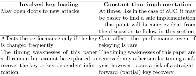
Table 3 compares and contrasts the two countermeasures.
Of course, a conservative approach would be to complicate the key loading procedure as well as implement the modulo (231−1) addition as a constant-time operation.
Table 3.A comparison of the suggested countermeasures
Involved key loading Constant-time implementation
May open doors to new attacks At times, like in the case of ZUC, it may be easier to find a safe implementation – this point will become evident from the discussion to follow in this section Affects the performance only if the key
is changed frequently
Can affect the performance even if rekeying is rare
The timing weaknesses of this paper still remain but cannot be exploited to recover the key or key-dependent infor-mation
The timing weaknesses of this paper are removed; any other similar timing anal-ysis, however, poses a risk of a straight-forward (partial) key recovery
1. Applying a secure hash function to the si’s of (1): A preimage and timing attack resistant hash function would solve our problem, ideally, if applied to thesi’s of (1). The size of the string [s15s14. . . s0] is 496 bits. For the coun-termeasure, this string is fed (after padding) into the compression function of a secure hash function, such as SHA-512 [16], on which there is no known preimage or timing attack despite years of scrutiny.10 The 512-bit output is truncated to 496 bits, replacing [s15s14. . . s0].
2. Employing 16 carefully chosen, secretN ×31(N ≥31) S-boxes:The inputs to the S-boxes (call themBi,i∈ {0,1, . . . ,15}) are thesi’s of (1). When the S-boxes are all secret,N = 31 can suffice even though at least 15 input bits are known constants. This is because(i)S-boxes are secret, and(ii)S-boxes with outputs larger than inputs can still accomplish Shannon’s confusion
[22] (note that Shannon’sdiffusion, as interpreted by Massey in [15], does not apply to stream ciphers) [1].
the carries into the bit position 30 being distributed close to uniformly (see footnote 4), there is about 2−7.42 probability that there is no end carry.11 Given that there is no end carry, the attacker deduces that there are fewer than two 1’s in [z1(30)z2(30). . . z6(30)]. Consequently, the attacker is able to recover at least 4 of the 6 z-bits but she cannot immediately ascertain if a particular bit guess is correct.
Despite the seeming infeasibility, even if an entire 31-bit block Bi(si) is recovered somehow, the input key bits cannot be recovered because Bi is secret.
Caveat: As mentioned earlier, an S-box implemented as a lookup table is stored in the cache if its elements are used frequently. One should therefore ensure that the Bi, i ∈ {0,1, . . . ,15}, are placed directly in the processor registers so that memory accesses are avoided. We borrow this idea from [18] where the authors also state that some architectures like the x86-64 and PowerPC AltiVec have register files sufficiently large to store large lookup tables.
Secret S-boxes have previously been used in ciphers (see e.g. GOST [25]). However,security through obscurityis in direct violation of the Shannon’s maxim [22]. Using a hash function like SHA-512 may be practical provided that the ZUC key is not changed very often.
For the constant-time implementation in software, our suggestion is to change theAdd() subroutine to the following (we call it “AddC()”, with the ‘C’ denoting ‘constant-time’):
u32 AddC(u32 x, u32 y) { u32 z = x + y;
z = (z & 0x7FFFFFFF) + ((z & 0x80000000) >> 31); return z;
}
Osviket al. provide some generic countermeasures against cache timing at-tacks in [18, Sect. 5]. We have already stated one of them, i.e., avoiding memory accesses by placing lookup tables in CPU registers wherever the architecture permits to do so. Some of the other suggestions of [18, Sect. 5] that are relevant to our cache timing analysis are:
1. disabling cache sharing,
2. disabling the cache mechanism per se,
3. adding noise to the cache access pattern (only mitigates the cache timing attack), and
4. adding noise to the timing information (again, only mitigates the attack).
Placing entire lookup tables in the cache, by the legitimate party, prior to encryption – a process known ascache warming – is suggested as a countermea-sure in [19]. Let us suppose that our lookup tables fit completely into the cache. Further let us assume that the adversary’s instructions or system processes do not evict the contents of these tables. Then, by placing the tables in the cache, one ensures that all S-box accesses are cache hits. Cache attacks that exploit the difference in the register loading time between a cache hit and a miss are precluded by this process. As we do not mount such cache attacks in this paper, cache warming is not a useful countermeasure here.
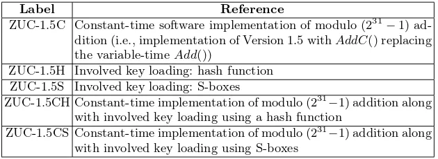
Nomenclature:To facilitate future reference, we label some of the above, secure modifications of ZUC in Appendix B.
6
Conclusions
In this paper, we have presented timing attacks on the stream cipher ZUC that recover, under certain practical circumstances, one key bit along with some key-dependent information with about 0.7 success probability and negligible time, memory and data. To the best of our knowledge, these are the first attacks on the ZUC cipher of Version 1.5. The following are other highlights of this paper.
– This is one of the very few and early papers analysing the cache timing resistance of stream ciphers. As noted in [14], block ciphers (mainly the AES) have been the prominent targets of cache timing attacks. Besides, cache timing analyses of stream ciphers are recent additions to the cryptanalysis literature, with the first paper (viz., [26]) being published as late as 2008 [14].
– The statistical timing attack is novel, to the best of our knowledge.
– The timing attacks of this paper warn that algorithms must be designed or implemented to resist single-round/iteration timing weaknesses. This single round can even belong to the key/IVsetup of the cipher.
The weaknesses we have found that lead us to the attacks may be certifi-cational. Nonetheless, we see a possibility for improving the attacks to recover a few other key bits by, for example, examining the cases where end carry is generated twice.
We have also proposed modifications to ZUC that resist not only the initia-tory timing attacks but, evidently, also their potential improvements suggested above. Analysis of these new schemes comes across to us as an interesting prob-lem for future research.
Update. The timing analysis presented in this paper was privately communi-cated by the author to the ETSI/SAGE before the2nd International Workshop on ZUC Algorithm and Related Topics. Subsequently, the reference C implemen-tation of ZUC was modified to the one in [9, Appendix A] (see also the “Docu-ment History” of [9]). This revised code is the latest and the ZUC specification with this code has been included in the LTE standards [11].
The latest code is essentially the code in [8] with two corrections: (i) the
if-statement in theLF SRW ithInitialisationM ode() subroutine is removed (it is to be noted that the effect of thisif-statement is not considered in the timing analysis of this paper), and (ii) the variable-timeAddM() subroutine (i.e., the Add() of Sect. 3) is replaced by the constant-timeAddC() subroutine of Sect. 5 – this idea, presented in this paper, was proposed independently by the author to the ETSI/SAGE [10, Sect. 12.9].
References
1. C. M. Adams, “Constructing Symmetric Ciphers Using the CAST Design Proce-dure”,Designs, Codes and Cryptography, vol. 12, pp. 283–316, 1997.
2. K. Aoki, J. Guo, K. Matusiewicz, Y. Sasaki, L. Wang, “Preimages for Step-Reduced SHA-2”, ASIACRYPT 2009 (M. Matsui, ed.), vol. 5912 ofLNCS, pp. 578–597, Springer, 2009.
3. M. Bellare, T. Kohno, “Hash Function Balance and Its Impact on Birthday At-tacks”, EUROCRYPT 2004 (C. Cachin, J. Camenisch, eds.), vol. 3027 ofLNCS, pp. 401–418, Springer, 2004.
4. D. J. Bernstein, “Cache-timing attacks on AES”, Preprint, 14thApril, 2005. Avail-able athttp://cr.yp.to/antiforgery/cachetiming-20050414.pdf.
5. J. L. Carter, M. N. Wegman, “Universal Classes of Hash Functions”,Journal of Computer and System Sciences, vol. 18(2), pp. 143–154, April 1979.
6. Data Assurance and Communication Security Research Center, “Workshop Presen-tations”, First International Workshop on ZUC Algorithm, 02nd–03rd December, 2010. Available athttp://www.dacas.cn/zuc10/.
7. ETSI/SAGE, “Specification of the 3GPP Confidentiality and Integrity Algorithms 128-EEA3 & 128-EIA3. Document 1: 128-EEA3 and 128-EIA3 Specification”, ETSI/SAGE Specification, Version 1.5, 04th January, 2011.
8. ETSI/SAGE, “Specification of the 3GPP Confidentiality and Integrity Algorithms 128-EEA3 & 128-EIA3. Document 2: ZUC Specification”, Version 1.5, 04th Jan-uary, 2011.
9. ETSI/SAGE, “Specification of the 3GPP Confidentiality and In-tegrity Algorithms 128-EEA3 & 128-EIA3. Document 2: ZUC Specifi-cation”, Version 1.6, 28th June, 2011 (Published in 2012). Available at http://www.gsma.com/aboutus/wp-content/uploads/2014/12/eea3eia3zucv16.pdf. 10. ETSI/SAGE, “Specification of the 3GPP Confidentiality and Integrity
Al-gorithms 128-EEA3 & 128-EIA3. Document 4: Design and Evaluation Re-port”, Version 2.0, 09th September, 2011 (Published in 2012). Available at http://www.gsma.com/aboutus/wp-content/uploads/2014/12/EEA3 EIA3 Design Evaluation v2 0.pdf.
http://www.gsma.com/aboutus/leadership/committees-and-groups/working-groups/fraud-security-group/security-algorithms.
12. T. Fuhr, H. Gilbert, J.-R. Reinhard, M. Videau, “A Forgery At-tack on the Candidate LTE Integrity Algorithm 128-EIA3”, Cryptol-ogy ePrint Archive, Report 2010/618, 08th December, 2010. Available at http://eprint.iacr.org/2010/618.pdf.
13. T. Isobe, K. Shibutani, “Preimage Attacks on Reduced Tiger and SHA-2”, Fast Software Encryption 2009 (O. Dunkelman, ed.), vol. 5665 ofLNCS, pp. 139–155, Springer, 2009.
14. G. Leander, E. Zenner, P. Hawkes, “Cache Timing Analysis of LFSR-Based Stream Ciphers”, IMA International Conference, Cryptography and Coding 2009 (M. G. Parker, ed.), vol. 5921 ofLNCS, pp. 433–445, Springer, 2009.
15. J. L. Massey, “An Introduction to Contemporary Cryptology”,Proceedings of the IEEE, vol. 76(5), pp. 533–549, May 1988.
16. National Institute of Standards and Technology, US Department of Com-merce, “Secure Hash Standard (SHS)”, Federal Information Process-ing Standards Publication, FIPS PUB 180-3, October 2008. Available at http://csrc.nist.gov/publications/fips/fips180-3/fips180-3 final.pdf. 17. K. Nyberg, J. Wall´en, “Improved Linear Distinguishers for SNOW 2.0”,Fast
Soft-ware Encryption 2006 (M. J. B. Robshaw, ed.), vol. 4047 ofLNCS, pp. 144–162, Springer, 2006.
18. D. A. Osvik, A. Shamir, E. Tromer, “Cache Attacks and Countermeasures: the Case of AES (Extended Version)”, revised 20th November, 2005. Available at http://www.osvik.no/pub/cache.pdf. Original version: Proceedings ofThe Cryp-tographers’ Track at the RSA Conference 2006 (D. Pointcheval, ed.), vol. 3860 of LNCS, pp. 1–20, Springer, 2006.
19. D. Page, “Theoretical Use of Cache Memory as a Cryptanalytic Side-Channel”, Cryptology ePrint Archive, Report 2002/169, 11th November, 2002. Available at http://eprint.iacr.org/2002/169.pdf.
20. P. Sarkar, “On Approximating Addition by Exclusive OR”, Cryptol-ogy ePrint Archive, Report 2009/047, 03rd February, 2009. Available at http://eprint.iacr.org/2009/047.pdf.
21. G. Sekar, S. Paul, B. Preneel, “New Weaknesses in the Keystream Generation Algorithms of the Stream Ciphers TPy and Py”,Information Security Conference 2007 (J. A. Garay, A. K. Lenstra, M. Mambo, R. Peralta, eds.), vol. 4779 ofLNCS, pp. 249–262, Springer, 2007.
22. C. E. Shannon, “Communication Theory of Secrecy Systems”,Bell Systems Tech-nical Journal, vol. 28(4), pp. 656–715, 1949.
23. O. Staffelbach, W. Meier, “Cryptographic Significance of the Carry for Ciphers Based on Integer Addition”, CRYPTO 1990 (A. Menezes, S. A. Vanstone, eds.), vol. 537 ofLNCS, pp. 601–614, Springer, 1991.
24. H. Wu, P. H. Nguyen, H. Wang, S. Ling, “Cryptanalysis of the Stream Cipher ZUC in the 3GPP Confidentiality & Integrity Al-gorithms 128-EEA3 & 128-EIA3”, Presentation at the Rump Ses-sion of ASIACRYPT 2010, 07th December, 2010. Available at http://www.spms.ntu.edu.sg/Asiacrypt2010/Rump%20Session-%207%20Dec%202 010/wu rump zuc.pdf.
26. E. Zenner, “A Cache Timing Analysis of HC-256”,Selected Areas in Cryptography 2008 (R. M. Avanzi, L. Keliher, F. Sica, eds.), vol. 5381 ofLNCS, pp. 199–213, Springer, 2009.
A
Practical Occurrences of
Γ
3,
Γ
5and
Γ
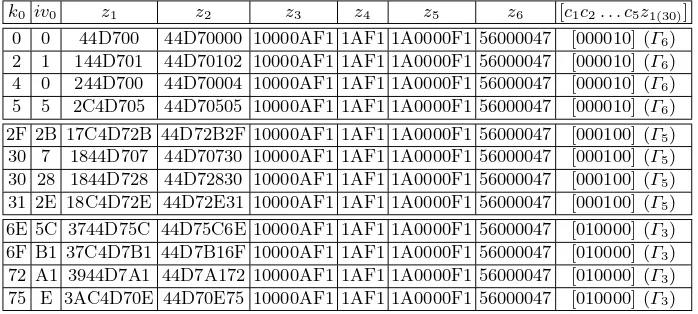
6Table 4 provides some example key-IV values that produce the favourable Γ -vectors (i.e., the -vectors that generate end carry exactly once).
Table 4. Some practical occurrences of the vectorsΓ3,Γ5 andΓ6 (all entries except those in the last column are in hexadecimal); in each of these examples,ki, ivi= 0∀i6= 0
k0 iv0 z1 z2 z3 z4 z5 z6 [c1c2. . . c5z1(30)]
0 0 44D700 44D70000 10000AF1 1AF1 1A0000F1 56000047 [000010] (Γ6) 2 1 144D701 44D70102 10000AF1 1AF1 1A0000F1 56000047 [000010] (Γ6) 4 0 244D700 44D70004 10000AF1 1AF1 1A0000F1 56000047 [000010] (Γ6) 5 5 2C4D705 44D70505 10000AF1 1AF1 1A0000F1 56000047 [000010] (Γ6) 2F 2B 17C4D72B 44D72B2F 10000AF1 1AF1 1A0000F1 56000047 [000100] (Γ5) 30 7 1844D707 44D70730 10000AF1 1AF1 1A0000F1 56000047 [000100] (Γ5) 30 28 1844D728 44D72830 10000AF1 1AF1 1A0000F1 56000047 [000100] (Γ5) 31 2E 18C4D72E 44D72E31 10000AF1 1AF1 1A0000F1 56000047 [000100] (Γ5) 6E 5C 3744D75C 44D75C6E 10000AF1 1AF1 1A0000F1 56000047 [010000] (Γ3) 6F B1 37C4D7B1 44D7B16F 10000AF1 1AF1 1A0000F1 56000047 [010000] (Γ3) 72 A1 3944D7A1 44D7A172 10000AF1 1AF1 1A0000F1 56000047 [010000] (Γ3) 75 E 3AC4D70E 44D70E75 10000AF1 1AF1 1A0000F1 56000047 [010000] (Γ3)
B
ZUC Modifications
Table 5.ZUC modifications: To each label we suffix a ‘+’ if one or more of the generic countermeasures suggested by Osviket al.in [18] are applied
Label Reference
ZUC-1.5C Constant-time software implementation of modulo (231−1) ad-dition (i.e., implementation of Version 1.5 withAddC() replacing the variable-timeAdd())
ZUC-1.5H Involved key loading: hash function ZUC-1.5S Involved key loading: S-boxes
ZUC-1.5CH Constant-time implementation of modulo (231−1) addition along with involved key loading using a hash function