Optimizing Chien Search usage in the BCH
Decoder
S. Murali Narasimham1, Ganesha A2
Associate Professor, Dept. of E&C, Bangalore Institute of Technology, Bangalore, Karnataka, India1
M. Tech Student [VLSI& ES], Dept. of E&C, Bangalore Institute of Technology, Bangalore, Karnataka, India2
ABSTRACT:In the decoding of the Bose ChaudhuriHochquenghem (BCH) codes, the most complex block is the Chien search block. In the decoding process of the BCH codes, error correction is performed bit by bit, hence they require parallel implementation. The area required to implement the Chien search parallel is more, hence a strength reduced parallel architecture for the Chien search is presented. In this paper, the syndrome computation is done using conventional method, the inversion-less Berlekamp Massey Algorithm is used for the solving the key equations.
KEYWORDS:BCH Decoder, parallel Chien search architecture
I.INTRODUCTION
The algebraic codes which are widely used and most powerful are the BCH and RS codes [3]. The powerful error correcting codes which are used more often in modern communication systems like wireless communication, optical communication, computer networks, magnetic recording systems, various storage devices are the BCH codes. Error pattern of size t or less can be designed in the BCH codes.
The three stages in the decoding process of the BCH codes are as follows: i) at first, the syndrome polynomial S(x) is calculated using the syndrome computation block, the received code word is given as input. The S(x) is given as input to the second stage; ii) the second block, the error locator polynomial is calculated by using different decoding algorithms such as Berlekamp Massey, Modified Euclidean etc. are used; iii) the last block, the Chien search block, where the roots of the error locator polynomial are calculated using the Chien search algorithm. The Chien search block involves more computations and complexity compared to other blocks.
It is frequently convenient to define error correcting codes in terms of the generator polynomials G(x). For the BCH code capable of correcting ‘t’ errors , generator polynomial is taken as the LCM of the minimal polynomials.
G(x) =LCM (Φ1, Φ2, Φ3, Φ4,…….Φ2t-1) (1)
The binary BCH code (n,k,t) exists for integer values m≥3, t≤2m-1, with there properties as given below:
n=2m-1 length of code word k ≥ n-mt number of information bits dmin≥ 2t+1 minimum hamming distance.
t error correcting capability.
Vol. 5, Issue 5, May 2016
II.BCH DECODER ARCHITECTURE
In Fig.1, the BCH decoder block diagram is shown. For a (n,k,t) BCH code in which, c(x) represents the transmitted code polynomial, r(x) the code polynomial that is received at the decoder end and e(x) represents the code polynomial where the error has occurred.
Fig.1 BCH decoder Block Diagram
A. Syndrome Computation
The first step in the decoding of the BCH codes is to calculate 2t syndromes Sj by evaluating the received code polynomial r(x) at. The code polynomial that is received can be represented by:
r(x) = (c(x) + e(x) ) (2)
The calculation of the 2t syndromes is given by Sj= 1 ≤ j ≤ 2t (3)
Where is the root of the primitive polynomial. We can also define syndrome polynomial
Sj= 1 ≤ j ≤ 2t (4)
B. Key Equation Solver
The co-efficient of the error locator polynomial in the decoding of the BCH codes are calculated in this stage. The input to this stage are the syndromes that are generated in the first stage of the decoding of the BCH codes. The error locator polynomial is given as: ( ) = + +⋯+ . The error locator polynomial is related with the syndromes generated in the first stage by the following relationship:
∑ (5)
The co-efficient of the error locator polynomial can be calculated by making use different decoding algorithms. In this paper the error locator polynomial co-efficient are found by the Inversion-less Berlekamp Massey Algorithm to solve the key equation presented in the [1] is used in this paper. The output of this block is the error locator polynomial σ(x).
C. Chien Search
In decoding process, the error locator polynomial σ(x) is acquired by performing the syndrome estimation and then
( ) =∑ (6)
The above equation gives the straight forward execution of the Chien search block. The routine Chien search circuit is as shown in Fig. 2.
Fig. 2. Conventional Chien Search
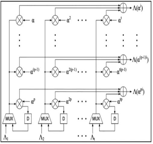
It produces an error-vector e in manner that, if is the root, then the (n-i) th component en-i=1; otherwise en-i=0 for all 0≤i≤n-1. In the conventional Chien search circuit only single error location is checked for on clock cycle, therefore it requires n clock cycles to compete the search process. The parallel architecture for the Chien search [5] can be used in order to replace this traditional Chien search circuit as shown in Fig. 3.
Moreover, without any hardware complexity, the long critical path in the parallel design can be adequately shortened asdiscussed in [6], [9]. The parallelization of the Chien circuit reduces the n clock cycles required for computation to n/p clock cycles with the parallel factor p. The hardware requirement for the parallel process also increases linearly with p. Thus the efficient decoder complexity basically relies upon the design of proficient Parallel Chien Search circuit.
Fig. 3.Parallel Architecture for Chien Search
III.PROPOSED ARCHITECTURE
Vol. 5, Issue 5, May 2016
Fig. 4. Strength Reduced Parallel Chien Search
The (15,7,2) BCH code is built on GF(24). The proposed Chien search circuit for the BCH decoder is as given in the block diagram shown in Fig. 4.
A. Chien Search Block
The Chien search circuit and error correction block is the biggest area and timing consumption. The signals Zs and Zb is the output from control unit to indicate zero syndrome. If Zs = 1 then no error occurs in the received polynomial code due to S(x)=0. If Zb =1 then only one error occurs in the received polynomial code. We should use multiplexer to select original bit or correction bit.To reduce the critical path, pipelined register must be added to the selector of the output. It can reduce the critical path significantly.
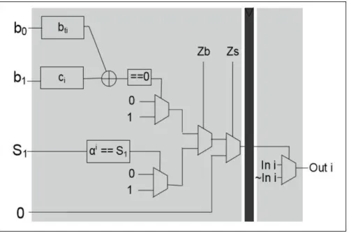
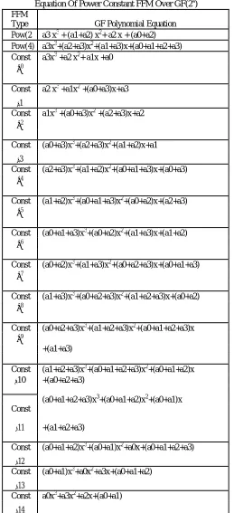
To obtain the optimal design, the architecture of the constant finite field multiplier has to be optimized by reducing the number of XOR gate. In table I, we can see that the coefficients of constant FFM have the same pattern between the equation and each other. By implementing this circuit, the count of XOR gates can be minimized, by reducing the same pattern coefficients. To replace FFM, block Ci and block bo is used as shown in Fig. 5.
Fig. 5. Proposed Strength-Reduced Pipelined Parallel Chien search
To find the roots of polynomials, each element in GF(24) has to be evaluated. Since there are 15 elements, we need signals C0-C14 to form Ci block. The assignment is determined based on coefficient pattern of FFM.The input of bocan be transformed to perform an optimized computation by manipulating its bits. As we know, the error locator polynomial is defined as:
so the value of b0+x2 can be computed in parallel computation by transforming the bits of b0. If x is the element of GF(24) and = , , … … … , then
= = , , … … … , , , , … … … , .
Table I
Equation Of Power Constant FFM Over GF(24) FFM
Type GF Polynomial Equation Pow(2 a3 x3 + (a1+a2) x2+ a2 x + (a0+a2) Pow(4) a3x3+(a2+a3)x2+(a1+a3)x+(a0+a1+a2+a3) Const a3x3 +a2 x2+ a1x +a0
α0
Const a2 x3 +a1x2 +(a0+a3)x+a3
α1
Const a1x3 +(a0+a3)x2 +(a2+a3)x+a2 α2
Const (a0+a3)x3+(a2+a3)x2+(a1+a2)x+a1
α3
Const (a2+a3)x3+(a1+a2)x2+(a0+a1+a3)x+(a0+a3) α4
Const (a1+a2)x3+(a0+a1+a3)x2+(a0+a2)x+(a2+a3)
α5
Const (a0+a1+a3)x3+(a0+a2)x2+(a1+a3)x+(a1+a2) α6
Const (a0+a2)x3+(a1+a3)x2+(a0+a2+a3)x+(a0+a1+a3) α7
Const (a1+a3)x3+(a0+a2+a3)x2+(a1+a2+a3)x+(a0+a2)
α8
Const (a0+a2+a3)x3+(a1+a2+a3)x2+(a0+a1+a2+a3)x α9
+(a1+a3)
Const (a1+a2+a3)x3+(a0+a1+a2+a3)x2+(a0+a1+a2)x α10 +(a0+a2+a3)
(a0+a1+a2+a3)x3+(a0+a1+a2)x2+(a0+a1)x
Const
+(a1+a2+a3)
α11
Const (a0+a1+a2)x3+(a0+a1)x2+a0x+(a0+a1+a2+a3)
α12
Const (a0+a1)x3+a0x2+a3x+(a0+a1+a2)
α13
Const a0x3+a3x2+a2x+(a0+a1)
Vol. 5, Issue 5, May 2016
B. Control Unit
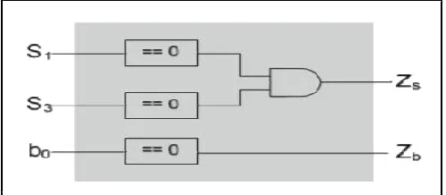
To perform our decoder system, we employ a simple control unit block that can support error correction. If there is no error in r(X), then the value of S1 and S3 is zero. If only one error occurs, then b0 of error locator polynomial is zero. The design of the control unit is as appeared if Fig. 6.
Fig. 6. Control Unit Block Diagram
IV.RESULTS
The design of the BCH decoder architectures described in the previous sections namely conventional, strength reduced architecture are expected to be simulated in Cadence NC Verilog simulator tool.In order to compare the complexity overhead and power consumptions, the two variants of the BCH decoder described in the previous in the paper are expected to be simulated using Cadence Encounter RTL compiler tool.
The power and area parameters of the BCH decoder design is given in the table II.
Table II
Area and power comparison of BCH decoder
Area(um2) Power(nW)
Design in [8] 14051 477932.501
Proposed 6961 151867.464
V. CONCLUSION
This paper presents the strength reduced parallel Chien search architecture which uses different set of constant power FFM over GF(2m). The proposed design has 3 clock latency since it consists of 3 pipelined stage. The optimized Chien search block consumes less area and power contrasted to the traditional Chien search BCH decoder. Hence the design presented in this paper can be used in modern communication systems.
REFERENCES
[1] Clifford Kraft,” Closed Solution of Berlekamp’s Algorithm for Fast Decoding of BCH Codes,” IEEE Transactions on Communications, Vol. 39, No.11, December1991.
[2] S. B. Wicker,V. K. Bhargava,” Reed-Solomon Codes and Their Applications,” Piscataway. NJ: IEEE Press, 1994. [3] S. B Wicker, “Error Control System for Digital Communication and Storage, Englewood Cliffs”, NJ Prentice-Hall, 1995.
[4] C. Paar,” Optimized arithmetic for Reed–Solomon encoders,” in Proc. IEEE Int. Symp. Inf. Theory, Ulm, Germany, Jun.–Jul. 1997, pp. 250–250. [5] L. Song, M.-L. Yu, M. S. Shaffer, “10- and 40-Gb/s forward error correction devices for optical communications,” IEEE J. Solid-State Circuits, vol. 37, no. 11, pp. 1565–1573, Nov. 2002.
[6] H. C. Chang, C. C. Lin, C. Y. Lee,” A Low Power Decoder for STM-16 Optical Communication,” in Proc. IEEE Asia-Pacific Conf. ASIC, Aug. 2002, pp. 351–354.
[7] R. E. Blahut,” Algebraic Codes for Data Transmission,” Cambridge, U.K.: Cambridge Univ. Press, 2003.
[9] Y. Chen, K.Parhi,” Small area parallel Chien search architectures for long BCH codes,” IEEE Trans. Very Large Scale Integr.(VLSI) Syst., vol. 12, no. 5, pp. 545–549, May 2004.
[10] H. Fan ,M. A. Hasan,” Fast bit parallel-shifted polynomial basis multipliers in GF(2m),” IEEE Trans. Circuits Syst. I ,Reg. Papers, vol. 53, no. 12, pp. 2606–2615, Dec. 2006.