Power Quality Improvement in Grid Connected Wind
Energy System
Mr.PasalaGopi & Ms. Koduru Sravanthi
[email protected] [email protected] m
A b s tract: Renewable energy resources (RES) are being increasingly connected in distribution systems utilizing power electronic converters. This paper presents a novel control strategy for achieving maximum benefits from these gr id-interfacing inverters when installed in 3-phase 4-wire distribution systems. The inverter is controlled to perform as a multi-function device by incorporating active power filter multi-functionality. The inverter can thus be utilized as: 1) power converter to inject power generated from RES to the grid, and 2) shunt APF to compensate current unbalance, load current harmonics, load reactive power demand and load neutral current. All of these functions may be accomplished either individually or simultaneously. With such a control, the combination of grid-interfacing inverter and the 3-phase 4-wire linear/non-linear unbalanced load at point of common coupling appears as balanced linear load to the grid. This new control concept is demonstrated with extensive MATLAB/Simulink simulation studies and validated through digital signal processor-based laboratory experimentalresults.
Key wo rd s : Active Power Filter (APF), Distributed Generation (DG), Distribution System, Grid Interconnection, Power Quality (PQ), Renewable Energy.
I.INTRODUCTION
Electric utilities and end users of electric power are becoming increasingly concerned about meeting the growing energy demand. Seventy five percent of total global energy demand is supplied by the burning of fossil fuels. But increasing air pollution, global warming concerns, diminishing fossil fuels and their increasing cost have made it necessary to look towards renewable sources as a future energy solution. Since the past decade, there has been an enormous interest in many countries on renewable energy for power generation. The market liberalization and government’s incentives have further accelerated the renewable energy sector growth. Renewable energy source (RES) integrated at distribution level is termed as distributed generation (DG). The utility is concerned due to the high penetration level of intermittent RES in distribution systems as it may pose a threat to network in terms of stability, voltage regulation and power-quality (PQ) issues. Therefore, the DG systems are required to comply with strict technical and regulatory frameworks to ensure safe, reliable and efficient operation of overall network. With the advancement in power electronics and digital control technology, the DG systems can now be actively controlled to enhance the system operation with improved PQ atPCC.
However, the extensive use of power electronics based equipment and non-linear loads at PCC generate harmonic currents, which may deteriorate the quality of power [2], [3]. Generally, current controlled voltage source inverters are used to interface the intermittent RES in distributed
system. Recently, a few control strategies for grid connected inverters incorporating PQ solution have been proposed. In [4] an inverter operates as active inductor at a certain frequency to absorb the harmonic current. But the exact calculation of network inductance in real-time is difficult and may deteriorate the control performance. A similar approach in which a shunt active filter acts as active conductance to damp out the harmonics in distribution network is proposed in [5]. In [6], a control strategy for renewable interfacing inverter based on– theory is proposed. In this strategy both load and inverter current sensing is required to compensate the load current harmonics. The non-linear load current harmonics may result in voltage harmonics and can create a serious PQ problem in the power systemnetwork.
Available online:
http://edupediapublications.org/journals/index.php/IJR/
Page | 1845and neutral current compensation in case of 3-phase 4-wire system. Moreover, with adequate control of grid-interfacing inverter, all the four objectives can be accomplished either individually or simultaneously. The PQ constraints at the PCC can therefore be strictly maintained within the utility standards without additional hardware cost.
Fig .1.Schematic of proposed renewable based d is trib u ted g en eratio n s y s tem.
The paper is arranged as follows: Section II describes the system Description. Hysteresis Current Control in Section III .Extensive experimental results are discussed in Section IV and, finally, Section V concludes thepaper.
II. SYSTEM DESCRIPTION A .To p o lo g y
Active power filters are power electronic devices that cancel out unwanted harmonic currents by injecting a compensation current which cancels harmonics in the line current. Shunt active power filters compens ate load current harmonics by injecting equal-but opposite harmonic compensating current. Generally, four-wire APFs have been conceived using four leg converters. This topology has proved better controllability than the classical three-leg four-wire.
B .Vo ltag e So u rce Co n v erter(VSC)
A Voltage Source Converter (VSC) is a power electronic device that connected in shunt or parallel to the system. It can generate a sinusoidal voltage with any required magnitude, frequency and phase angle. It also converts the DC voltage across storage devices into a set of three phase AC output voltages. It is also capable to generate or absorbs reactive power. If the output voltage of the VSC is greater than AC bus terminal voltages, is said to be in capacitive mode. So, it will compensate the reactive power through AC system. The type of power switch used is an IGBT in anti-parallel with a diode. The three phase four leg VSI is modeled in Simulink by using IGBT. As in the Fig.1 the system consist of an RES connected to the dc-link ofagrid-interfacinginverter.Thevoltagesourceinverter
interfaces the renewable energy source to the grid. The RES may be a DC source or an AC source with rectifier coupled to dc- link. The fuel cell and photovoltaic energy sources generate power at variable low dc voltage, but the production of power in variable speed wind turbine is variable ac voltage. So before connecting on to a dc-link, the power generated from these renewable sources needs to be power conditioned (i.e., dc/dc or ac/dc). Usually the fuel cell integration is provided by using a unidirectional DC/DC converter (to obtain regulated high voltage DC), an inverter and a filter in order to accommodate the DC voltage to the required AC voltage (single phase or three phases).
A .DC-Lin k Vo ltag e an d Po wer Co n tro lOp eratio n Because of the intermittent nature of RES, the generated power is of variable nature. The dc-link connected aids in transferring this variable power from RES to the grid. RES are represented as current sources connected to the dc-link of a grid-interfacing inverter. The current injected by renewable into dc-link at voltage level V dc can be givenas
(1)
Where PRES is the power generated from RES. The
current flow on the other side of dc-link can be represented as,
(2)
Where, PINV- total power available at grid-interfacing
inverter side, PG- active power supplied to the grid and
inverter losses, and PLOSS- inverter losses. If inverter losses
are negligible then, PRES = PG.
Fig .2. Block diagram represen tatio n o f g rid -in terfacin g in v erter co n tro l.
B .Co n tro l o f Grid In terfacin g In v erter
inverter. The proposed approach is mainly concerned about the regulation of power at PCC during three conditions like, when 1) PRES = 0; 2) PRES < total power (PL); and 3) PRES >
PL. During the power management operation, the inverter is
controlled in such a way that it always draws/ supplies fundamental active power from/ to the grid. If the load connected to the PCC is non-linear or unbalanced or the combination of both, the given control approach also compensates the harmonics, unbalance, and neutral current. By the control, duty ratio of inverter switches are varied in a power cycle in order to get the combination of load and inverter injected power to be appearing as balanced resistive load to the grid. The exchange of active power in between renewable source and grid can be obtained from the regulation of dc-link voltage. Thus the output of dc-link voltage regulator results in an active current (Im). The multiplication of this active current component (Im) with unity grid voltage vector templates (Ua, Ub, and Uc) generates the reference grid currents (I*a, I*b, and I*c) for
the control process. The reference grid neutral current (I*n)
is set to zero, being the instantaneous sum of balanced grid currents. Phase locked loop (PLL) is used to generate unity vector template from which the grid synchronizing angle (0) isobtained.
(3)
(4)
(5)
To eliminate the presence of switching ripples on the dc- link voltage and in the generated reference current signals, the actual dc-link voltage (Vdc) is sensed and passed through
a first-order low pass filter (LPF). The difference of this filtered dc-link voltage and reference dc-link voltage (V*dc)
is given to a discrete- PI regulator to maintain a constant dc- link voltage under varying generation and load conditions. The error in the dc-link voltage Vdcerr (n) at the sampling
instant is given by:
(6)
III.HYSTERESIS CURRENTCONTROL
The hysteresis current control (HCC) is the easiest control method to implement; it was developed by Brod and Novotny in 1985. The shunt APF is implemented with three phase current controlled VSI and is connected to the ac mains for compensating the current harmonics. The VSI gate control signals are brought out from hysteresis band current controller. A hysteresis current controller is implemented with a closed loop control system and waveforms are shown in Fig .3. An error signal is used to control the switches in a voltage source inverter. This error is the difference between the desired current and the current being injected by the inverter. If the error exceeds the upper
arm is turned off and the lower switch is turned on. As a result, the current starts decaying.
Fig .3. Waveform o f Hysteresis current controller.
If the error crosses the lower limit of the hysteresis band, the lower switch of the inverter arm is turned off and the upper switch is turned on. As a result, the current gets back into the hysteresis band. The minimum and maximum values of the error signal are emin and emax respectively. The
range of the error signal emax -emin directly controls the
amount of ripple in the output current from the VSI.
IV. SIM ULATIONRESULTS
In order to verify the proposed control approach to achieve multi-objectives for grid interfaced DG systems connected to a 3-phase 4-wire network, an extensive simulation study is carried out using MATLAB/Simulink. A 4-leg current controlled voltage source inverter is actively controlled to achieve balanced sinusoidal grid currents at unity power factor (UPF) despite of highly unbalanced nonlinear load at PCC under varying renewable generating conditions. A RES with variable output power is connected on the dc-link of grid-interfacing inverter. An unbalanced 3- phase 4-wire nonlinear load, whose unbalance, harmonics, and reactive power need to be compensated, is connected on PCC. The waveforms of grid voltage grid currents Positive values of grid active-reactive powers and inverter active- reactive powers imply that these powers flow from grid side towards PCC and from inverter towards PCC, respectively.
Available online:
http://edupediapublications.org/journals/index.php/IJR/
Page | 1847constant, this additional power generated from RES flows towards grid, which can be noticed from the increased magnitude of grid current as indicated by its profile.
Fig .4. Simu latio n res u lts : (a) Grid v o ltag es , (b ) Grid Cu rren ts (c) Un b alan ced lo ad cu rren ts , (d ) In v erter Cu rren ts .
The active and reactive power flows between the inverter, load and grid during increase and decrease of energy generation from RES can be noticed from Fig. 5.
The dc-link voltage across the grid- interfacing inverter (Fig. 5(d)) during different operating condition is maintained at constant level in order to facilitate the active and reactive power flow. Thus from the simulation results, it is evident that the grid-interfacing inverter can be effectively used to compensate the load reactive power, current unbalance and current harmonics in addition to active power injection from RES. This enables the grid to supply/ receive sinusoidal and balanced power atUPF.
Fig .5. Simulation results: (a) Grid, (b) Load, (c) PQ-In v erter, (d ) d c -lin k v o ltag e.
Fig .7. Inverter.
Fig 8. Load Voltage and current.
Fig .9. Inverter voltage and current.
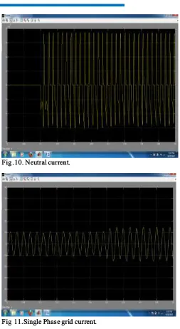
Fig .10. Neutral current.
Fig 11.Single Phase grid current.
Available online:
http://edupediapublications.org/journals/index.php/IJR/
Page |1849Fig 13. THD co mp aris o n with s elected s ig n al.
V. CONCLUSION
This paper has presented a novel control of an existing grid interfacing inverter to improve the quality of power at PCC for a 3-phase 4-wireDGsystem. It has been shown that the grid-interfacing inverter can be effectively utilized for power conditioning without affecting its normal operationof real power transfer. The grid-interfacing inverter with the proposed approach can be utilizedto:
Inject real power generated from RES to the grid, and/or,
Operate as a shunt Active Power Filter(APF).
This approach thus eliminates the need for additional power conditioning equipment to improve the quality of power at PCC. Extensive MATLAB/Simulink simulation as well as the DSP based experimental results have validated the proposed approach and have shown that the grid - interfacing inverter can be utilized as a multi-function device. It is further demonstrated that the PQ enhancement can be achieved under three different scenarios: 1) PRES = 0,
2) PRES < PLOAD, and 3) PRES > PLOAD. The current
unbalance, current harmonics and load reactive power, due to unbalanced and non-linear load connected to the PCC, are compensated effectively such that the grid side currents are always maintained as balanced and sinusoidal at unity power factor. Moreover, the load neutral current is prevented from flowing into the grid side by compensating it locally from the fourth leg of inverter. When the power generated from RES is more than the total load power demand, the grid-interfacing inverter with the proposed control approach not only fulfills the total load active and reactive power demand (with harmonic compensation) but also delivers the excess generated sinusoidal active power to the grid at unity powerfactor.
VI.REFERENCES
[1] Mukhtiar Singh, Student Member, IEEE, Vinod Khadkikar, Member, IEEE, Ambrish Chandra, Senior
Member, IEEE, and Rajiv K. Varma, Senior Member, IEEE, “Grid Interconnection of Renewable Energy Sources at the Distribution Level With Power-Quality Improvement Features”, IEEE Transactions on Power Delivery, Vol. 26, No. 1, January 2011.
[2] J. M. Guerrero, L. G. de Vicuna, J. Matas, M. Castilla, and J. Miret, “A wireless controller to enhance dynamic performance of parallel inverters in distributed generation systems,” IEEE Trans. Power Electron., vol. 19, no. 5, pp. 1205–1213, Sep. 2004.
[3] J. H. R. Enslin and P. J. M. Heskes, “Harmonic interaction between a large number of distributed power inverters and the distribution network,” IEEE Trans. Power Electron, vol. 19, no. 6, pp. 1586–1593, Nov. 2004.
[4] U. Borup, F. Blaabjerg, and P. N. Enjeti, “Sharing of nonlinear load in parallel-connected three-phase converters,” IEEE Trans. Ind. Appl., vol. 37, no. 6, pp. 1817–1823, Nov./Dec. 2001.
[5] P. Jintakosonwit, H. Fujita, H. Akagi, and S. Ogasawara, “Implementation and performance of cooperative control of shunt active filters for harmonic damping throughout a power distribution system,” IEEE Trans. Ind. Appl., vol. 39, no. 2, pp. 556–564, Mar./Apr. 2003.
[6] J. P. Pinto, R. Pregitzer, L. F. C. Monteiro, and J. L. Afonso, “3-phase 4-wire shunt active power filter with renewable energy interface,” presented at the Conf. IEEE Renewable Energy & Power Quality, Seville, Spain, 2007. [7] F. Blaabjerg, R. Teodorescu, M. Liserre, and A. V. Timbus, “Overview of control and grid synchronization for distributed power generation systems,” IEEE Trans. Ind. Electron., vol. 53, no. 5, pp. 1398–1409, Oct. 2006.
[8] J. M. Carrasco, L. G. Franquelo, J. T. Bialasiewicz, E. Galván, R. C. P. Guisado, M. Á. M. Prats, J. I. León, and N. M. Alfonso, “Power electronic systems for the grid integration of renewable energy sources: A survey,” IEEE Trans. Ind. Electron., vol. 53, no. 4, pp. 1002–1016, Aug. 2006.
[9] B. Renders, K. De Gusseme, W. R. Ryckaert, K. Stockman, L. Vandevelde, and M. H. J. Bollen, “Distributed generation for mitigating voltage dips in low-voltage distribution grids,” IEEE Trans. Power. Del., vol. 23, no. 3, pp. 1581–1588, Jul. 2008.
[10] V. Khadkikar, A. Chandra, A. O. Barry, and T. D. Nguyen, “Application of UPQC to protect a sensitive load on a polluted distribution network,” in Proc. Annu. Conf. IEEE Power Eng. Soc. Gen. Meeting, 2006, pp. 867–872. [11] M. Singh and A. Chandra, “Power maximization and voltage sag/swell ride-through capability of PMSG based variable speed wind energy conversion system,” in Proc. IEEE 34th Annu. Conf. Indus. Electron. Soc., 2008, pp. 2206–2211.
M r. PASALA GOPI was born in India. He is wo rkin g as a A ssociate Professo r in Dep artmen t o f EEE at PBR VITS, Kav ali, A .P. an d
Pu rsuing h is Ph.D from K L Univers ity , Gu n tu r, A . P. His res earch in teres ts
are in the areas o f Po wer Sy s tem Stab ility , Op eratio n & Co n tro l an d FA CTS.
Email id : p as ala.ep e07@g mail.co m
M s . KODURU SRAVANTHI was born in India. She is p u rsuing M.Tech degree in Power electronics in EEE Dep artment in Visvodaya Institute Of Technology and Science, Kavali, SPSR Nellore District,
A n dhra Pradesh State , India.