Wind Energy Conversion System Connected
With Grid Using Permanent Magnet
Synchronous Generator (PMSG)
Sourav Ghosh1, Prof. Pradip Kumar Saha2, Prof. Gautam Kumar Panda3
PG scholar, Department of Electrical Engineering, Jalpaiguri Government Engineering College, Jalpaiguri, West
Bengal, India1
Professor, Department of Electrical Engineering, Jalpaiguri Government Engineering College, Jalpaiguri, West Bengal,
India2
HOD and Professor, Department of Electrical Engineering, Jalpaiguri Government Engineering College, Jalpaiguri,
West Bengal, India3
ABSTRACT- This paper deals with permanent magnet synchronous generator (PMSG) based wind energy conversion system (WECS) integrated with grid with two back to back connected converters with a common DC link. The aim of this research is to model control of direct driven 1.5 MW wind turbine permanent magnetic synchronous generator (PMSG) which feeds alternating current (AC) power to the utility grid .The machine side converter is used to extract maximum power from the wind. In this paper a study of WECS is done by using a constant speed direct-driven wind turbine in Matlab. Moreover, by maintaining the dc link voltage at its reference value, the output ac voltage of the inverter can be kept constant irrespective of variations in the wind speed and load. An effective control techniques to extract maximum power from wind turbine is maximum power point tracking controller (MPPT), grid side controller also called voltage controller, pitch controller, phase lock loop controller (PLL) also used in this project, transformer used for isolation purpose, crow bar circuit used for protection the whole system.
KEYWORDS-Permanent magnet synchronous generator(PMSG), wind energy conversion system(WECS), back to back PWM converter IGBT based, DC link capacitor, Direct-Driven, MPPT controller, PLL loop, generator side converter control, grid side converter control, pitch controller, crow bar protection and transformer.
I. INTRODUCTION
In recent years, the electrical power generation from renewable energy sources, such as wind, is increasingly attraction interest because of environmental problem and shortage of traditional energy source in the near future. Nowadays, the extraction of power from the wind on a large scale became a recognized industry. It holds great potential showing that in the future will become the undisputed number one choice form of renewable source of energy. The force that pushes this technology is the simple economics and clean energy. As a consequence of rising fossil fuel price and advanced technology, more and more homes and businesses have been installing small wind turbines for the purposes of cutting energy bills and carbon dioxide emissions, and are even selling extra electricity back to the national grid.
directly connected to the power grid. In order to achieve the condition that the generator output power is suitable for grid-connection, it is necessary to use a controller to manage the output produced by the wind turbine generator.
Permanent magnet machines are characterized as having large air gaps, which reduce flux linkage even in machines with multi-magnetic poles. As a result, low-rotational-speed generators can be manufactured with relatively small sizes with respect to its power rating. Moreover, the gearbox can be omitted due to low rotational Speed in the PMSG wind generation system, thus resulting in low cost. To increase the efficiency, to reduce the weight of the active parts, and to keep the end winding losses small, direct-drive generators are usually designed with a large diameter and small pole pitch. Compared with the traditional electrically excited synchronous generator, the requirement of a larger pole number can be met with permanent magnets which allow small pole pitch . In addition, permanents magnet synchronous generators (PMSGs) have the high torque density and the absence of excitation losses. Furthermore, the performance of PM’s is improving and the cost of PM is decreasing in recent years, the direct-drive permanent magnet wind generators have recently received increasing attention, especially for offshore wind energy. Thanks to the application of high energy PM materials such as neodymium-iron-boron, the volume and cost of this type of machine can be dramatically reduced. The distinct advantages offered by PMSGs are simple rotor design without field winding. The absence of field windings also results in higher efficiency since heat dissipation is avoided. PMSG is gaining a lot of attention for WECS due to compact size, high reliability higher power to weight ratio, reduced losses and robustness.
WIND TURBINE MODEL
II. MODEL OF PMSG WIND TURBINE
(A)Structure of PMSG Wind Turbine: The basic of PMSG wind turbine structure shown on Figure 2. The wind
turbine generates torque from wind power. The torque is transferred through the generator shaft to the rotor of the generator. The generator produces an electrical torque, and the difference between the mechanical torque from the wind turbine and the electrical torque from the generator determines whether the mechanical system accelerates, decelerates, or remains at constant speed.
Fig-2.General wind turbine PMSG system with control schemes
(B).Model of Wind Turbine: The wind turbine analyzed is a classic three-bladed horizontal-axis (main
shaft) wind turbine design with the corresponding pitch controller. The output mechanical power available from a wind turbine can be expressed through the following algebraic relation
Where, ρ - air density
V – Wind Speed
Cp - Coefficient of Performance (or Power Coefficient) of the wind turbine
A – Area swept by the rotor blades of the wind Turbine
The power coefficient Cp is a nonlinear function of the blade pitch angle β and the tip-speed ratio by λ as given by,
λ=
Where, ωm - Angular speed of the turbine rotor, R-Radius of the turbine Blades
The power coefficient Cp can be expressed as,
=
The torque of the wind turbine can be expressed as
=
(C)Modeling of Permanent Magnet Synchronous Genarator:-Permanent magnet synchronous machines/generators (PMSMs/PMSG)s play key role in direct-drive wind power generation systems for transforming the mechanical power into electrical power. A rigorous mathematical modeling of the PMSG is the prerequisite for the design of the machine control algorithms as well as the analysis of the steady-state and dynamic characteristics of wind energy conversion
systems. In this section, the mathematical model of a PMSG in both the natural abc three-phase stationary reference
frame and dq synchronously rotating reference frame will be developed.
Fig.4.Cross-section view of the PMSG
The figure shows the cross-sectional view of a three-phase, two-pole PMSG.The fixed abcaxes denote the direction of
the MMFs of the a, b and c phase windings, which are induced by the time varying three-phase AC currents in these
stator phase windings. The flux caused by the permanent magnet is in the direction of the d-axis fixed at the rotor.
Here, the dq-axes are rotating at the same angular speed of the PMs and rotor. Also,Ѳ ,denotes the angle between the d
-axis and the stationary a-axis.
III. CONTROL OF PMSG WIND TURBINE
(A)Generator side inverter control:- The genera tor side inverter is controlled to catch maximum power from available wind power. To control electromagnetic torque we have to control q axis current iqs with the assumption ids is
zero. The tip speed ratio λ taken into account.The error ω(ref) is produced. Therefore the error of w(ref) and w(s) is
rescued to PI controller to produce q-axis current component iqs(ref) which put into SVPWM. The d-axis current ids(ref) is set to zero because d-axis current control is adopted.
Fig.5.Generator side inverter control
(B)Grid-side inverter control:- ed is d-axis output voltage of the grid respectively, ω is the angular frequency in
q-axis moderate to control active and reactive power.The inner current loop is controlled by PI controller similar to generator-side inverter.The out-put voltage loop produced PI controller for calculating the error between Udc and Udc(ref) produced Id(ref).Therefore q-axis current is set to zero to decoupling control of the active power P and reactive power Q by mode rating the d-axis current id and q-axis current iq.
Fig.6. Grid –side inverter control
(C)Pitch angle control:- The system of aerodynamic control plays an important role in regulating the mechanical power. Pitch angle controller is based on the principle which is changing the blades angle at the revolutions over the maximal generator speed as well as protecting the generator before overloading at high wind speeds. The optimal angle for the wind speed below the nominal value is approximately zero and then it increases with the wind speed growing. It has considerable impact on the performance coefficient and on the value of the turbine torque in
(D)MPPT control:-The MPPT is a control method which control the wind turbine rotor speed by controlling torque of the generator. The blade pitching drive is a mechanical equipment which has a delay in response time in rapidly changing wind condition. However in, order to maximize the power production the rotor speed of the generator can be controlled electrically. This is usually done by adopting the rotor speed to the optimum tip speed ratio.
(E)PLL Control:- It is a control system that generates an output signal whose phase is related to the phase of an input signal. It is easy to initially visualize as an electronic circuit consisting of variable frequency oscillator and a phase detector. The oscillator generates a periodic signal .The phase detector compares the phase of the signal with the phase of the input periodic signal and adjust the oscillator to keep the phase matched.
IV. BACK TO BACK PWM INVERTER
WECS consist of a PMSG connected to a AC-DC IGBT-based PWM rectifier and a DC-AC IGBT based PWM inverter, with a LCL filter. This filter increase quality of the current.
V. CROW-BAR PROTECTION
A crowbar circuit is an electrical circuit used to prevent an overvoltage condition of a power supply unit from damaging the circuits attached to the power supply. It operates by putting a short circuit or low resistance path across the voltage source, much as if one dropped a tool of the same name across the output terminals of the power supply. Crowbar circuits are frequently implemented using a thyristor, TRIAC.
VI. TRANSFORMER
VII. SIMULATION
The given simulation model based on the principle is that a fixed wind speed is consider in this model ,the kinectic energy of wind speed is converted in electrical energy with the help of turbine shaft and PMSG. In this model we used several controller(MPPT controller, PLL controller, Pitch controller, Grid side Inverter controller, Generator side Inverter controller)which help us to send this electrical energy to the National Grid.
Fig.7. Simulation of wind energy conversion system in MAT LAB
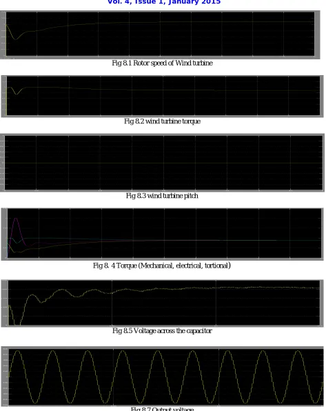
VIII. RESULT
Fig 8.1 Rotor speed of Wind turbine
Fig 8.2 wind turbine torque
Fig 8.3 wind turbine pitch
Fig 8.4 Torque (Mechanical, electrical, tortional
)
Fig 8.5 Voltage across the capacitor
Fig 8.7 Output voltage
IX. CONCLUSION
This study analyzes the control strategies as well as models and designs and simulates the whole autonomous system of PMSG wind turbine feeding AC power to the utility grid in Matlab Simulink . The simulation results show that the combination of pitch angle controller, generator-side inverter controller, and grid-side inverter controller has good dynamic and static performance. The maximum power can be tracked and the generator wind turbine can be operated in high efficiency. DC-link voltage is kept at stable level for decoupling control of active and reactive power. Hence, the output will get the optimum power supply for the grid.
REFERENCES
[1] Jay Verma,Yogesh , Tiwari, Anup Mishra, Nirbhaya Singh ,”Performance, Analysis and Simulation of Wind Energy Conversion System Connected with grid”. IJRTE, ISSN: 2277-3878 Volume-2, Issue-6, January2014.
[2]D Mary,Shinosh Mathew,Sreejith K,,”Modeling and Simulation of Grid Connected Wind Energy System.”,IJSCE,ISSN: 2231-2307, Volume-3, Issue-1, and March 2013.
[3] A.Bharathi sankar, Dr.R.Seyezhai,”MATLAB Simulation of Power Electronic Converter for PMSG Based Wind Energy Conversion
System”,IJIREEICE,Vol.1,Isuue.8,November 2013
[4] Gaurav Singh Bhandari,Dr.M.Kowaslya,”Power Electronics Converter for Grid Intregrated Vriable Speed Wind
Turbine”,IJDR,Vol.4,Issue.3,March 2014
[5] Rajveer Mittal,K.S.Sandhu,D K. Jain,”Grid Voltage Control of Inverter Interfaced Wind Energy Conversion
System”,IJESD,Vol.2,Issue.5,October 2011.
[6] J. Chen, H. B. Wu, M. Sun, W. N. Jiang, L. Cai, and C. Y. Guo, “Modeling and simulation of directly driven wind turbine with permanent magnet synchronous generator,” in Proceedings of the 2012 IEEE Innovative Smart Grid Technologies, Asia (ISGT '12), pp. 1–5, May 2012.
BIOGRAPHY
Sourav Ghosh was born in West Bengal ,India on January 11,1987. He received his B.Tech degree in Electrical Engineering from Aryabhatta Institute of Engineering and Management, Durgapur, West Bengal in 2010. currently he is doing M.Tech degree in Power Electronics and Drives from Jalpaiguri Govt. Engineering College, Jalpaiguri, West Bengal.
Prof. Pradip Kumar Saha, Professor, Jalpaiguri Government Engineering College, Jalpaiguri,WB-735102. BE (Electrical) from B.E. College, Shibpore. M.Tech((Electrical) Specialization: Machine Drives & Power Electronics from IIT- Kharagpur. PhD from University of North Bengal. FIE, MISTE, Certified Energy Auditor.
Prof. Goutam Kumar Panda, Professor and Head, Department of Electrical Engineering, Department of Electrical Engineering, Jalpaiguri Government Engineering College, Jalpaiguri,WB-735102,BE (Electrical ) from J.G.E. College, Jalpaiguri, M.E.E(Electrical) Specialization: Electrical Machines & Drives from Jadavpur University. PhD from University of North Bengal. FIE, MISTE, Certified Energy Auditor .