ISSN (Print) : 2320 – 3765 ISSN (Online): 2278 – 8875
I
nternational
J
ournal of
A
dvanced
R
esearch in
E
lectrical,
E
lectronics and
I
nstrumentation
E
ngineering
(A High Impact Factor, Monthly, Peer Reviewed Journal)
Website: www.ijareeie.com
Vol. 7, Issue 4, April 2018
To Study Performance Analysis of IUPFC
using Matlab Simulink Model
Latika Shrivas
1, Pragya Patel
2, Raghvendra Singh
3M.Tech Scholar, Dr. C V Raman Institute of Science and Technology, Chhattisgarh, India1
Asst. Professor, Department of EE, Dr. C V Raman Institute of Science and Technology, Chhattisgarh, India 2 Asst. Professor, Department of EE, Dr. C V Raman Institute of Science and Technology, Chhattisgarh, India 3
ABSTRACT: In modern power systems, there is a increase in power demand continuously. To meet the change in power demand the power flow on the transmission lines are actively controlled. Power flow controlling devices are required for such purpose among all PE Power flow control devices; the Unified Power Flow Controller (UPFC) is used to control the power flow on the single transmission line and Interline power flow controller (lPFC) is used to control the power flow in the parallel transmission lines or on the multi-lines. Interline unified power flow controller (IUPFC) is a new device, which is the modified version UPFC and IPFC.
In this paper, it is proposed to develop Interline unified power flow controller (IUPFC) using 48 pulse voltage source converter to provide the quality power supply. Shunt and series converters are combined together. It improves the power flow on one transmission line in a power system and it regulates bus voltage in another transmission line. IUPFC is a combination of STATCOM and SSSC.The performances of the IUPFC are to be analyzed on the parallel transmission lines. The model has to be simulating with Matlab Simulink program to demonstrate system behavior of Interline unified power flow controller. Numerical results are to be demonstrated on the practical Bus system with the Interline unified power flow controller model. It has to be validating that there is a possibility of regulating active power flow, reactive power flow and minimizing the power losses simultaneously with proposed IUPFC parameter.
KEYWORDS: Flexible AC Transmission System (FACTS), 48 pulses Voltage source Converter (VSC), SSSC, STATCOM, Interline Unified power Flow control.
I. INTRODUCTION
ISSN (Print) : 2320 – 3765 ISSN (Online): 2278 – 8875
I
nternational
J
ournal of
A
dvanced
R
esearch in
E
lectrical,
E
lectronics and
I
nstrumentation
E
ngineering
(A High Impact Factor, Monthly, Peer Reviewed Journal)
Website: www.ijareeie.com
Vol. 7, Issue 4, April 2018
In the year 2002 a basic characteristic of Voltage Source Converter based Interline Power Flow Controller was discussed in paper [7] by the author Jianhong Chen T.T.Lei. Along with two basic control scheme, namely (i) Special Control Scheme and (ii) General control Scheme. The Special control scheme is designed for the power flow control of a transmission system with two identical parallel lines while the general control scheme can be used to solve the power flow control problem in a multi-line transmission system. Both special and general control schemes are based on the decoupled PI controller. A current source converter topology based inter line power flow controller was proposed in paper [8], along with decoupled stat-feedback control for the injected voltage with a separated dc current controller. The dynamic model of the system is derived and divided into a liner part and a nonlinear part. The linear part is controlled in an inner loop by a decoupled state-feedback controller. The nonlinear part is controlled in an outer loop by a PI controller which regulates the dc side current
In paper [9] the author proposed the 48 pulse voltage source converter for the Interline unified power flow controller. The proposed converter will have the capability of controlling the power flow on the parallel transmission lines. In this paper a detailed switching level simulation model of IUPFC was developed on the Matlab Simulink environment. The IUPFC was developed to regulate the system voltage by compensating the reactive power.
II. PROBLEM IDENTIFICATION
The first generation of the FACTs devices. In this period, the typical devices are including tap changing and phase changing transformer, synchronous generator and series capacitors. Except the series capacitors, which could also be called capacitor bank, others are dynamic devices. These devices are mainly controlled at the generation side of the power grid and the cost is typically expensive. When talk about the series capacitors, the drawback of this device could hardly be omitted. Since the device is made up of many fixed-capacitance capacitors, it could hardly be controlled to give the real not-fixed capacitance to the grid. The second generation of the FACTs devices. It could be classified into two categories: thyristor-based devices and fully-controlled devices based compensator. The thyristor is called half controlled device, because it can only be controlled to switch on but auto cut-off. Static Var Compensator (SVC) and Thyristor-Controlled Series Capacitor (TCSC) are included in this category. The fully controlled devices mainly involve GTO etc. The Static Compensator (STATCOM), Solid State Series Compensator (SSSC), Unified Power Flow Controller (UPFC) and HVDC- Voltage Source Converter (HVDC-VSC) are included in this group.AC transmission lines form the backbone of the electricity grid in most countries and continents. The power flow will follow the path of least impedance and is uncontrollable, unless active grid elements are used. To enhance the functionality of the ac transmission grid, flexible ac transmission systems (FACTS) support the transmission grid with power electronics. These devices offer a level of control to the transmission system operator. A interline unified power-flow controller (IUPFC) is the most versatile of these FACTS devices. A transmission line equipped with a IUPFC can control the balance of the transmitted power between parallel lines and, as such, can optimize the use of the transmission grid for all parallel power flows.
III. METHODOLOGY
ISSN (Print) : 2320 – 3765 ISSN (Online): 2278 – 8875
I
nternational
J
ournal of
A
dvanced
R
esearch in
E
lectrical,
E
lectronics and
I
nstrumentation
E
ngineering
(A High Impact Factor, Monthly, Peer Reviewed Journal)
Website: www.ijareeie.com
Vol. 7, Issue 4, April 2018
IV. SIMULINK MODEL OF IUPFC
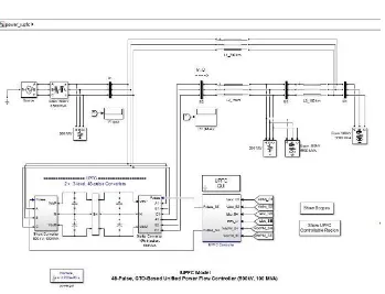
Figure 1 Simulink model of IUPFC
A Interline Unified Power Flow Controller (IUPFC) is used to control the power flow in a 500 kV transmission system. The UPFC located at the left end of the 75-km line L2, between the 500 kV buses B1 and B2, is used to control the active and reactive powers flowing through bus B2 while controlling voltage at bus B1. It consists of two 100-MVA, three-level, 48-pulse GTO-based converters, one connected in shunt at bus B1 and one connected in series between buses B1 and B2. The shunt and series converters can exchange power through a DC bus. The series converter can inject a maximum of 10% of nominal line-to-ground voltage (28.87 kV) in series with line L2.
This pair of converters can be operated in three modes:
Unified Power Flow Controller (UPFC) mode, when the shunt and series converters are interconnected through the DC bus. When the disconnect switches between the DC buses of the shunt and series converter are opened, two additional modes are available:
ISSN (Print) : 2320 – 3765 ISSN (Online): 2278 – 8875
I
nternational
J
ournal of
A
dvanced
R
esearch in
E
lectrical,
E
lectronics and
I
nstrumentation
E
ngineering
(A High Impact Factor, Monthly, Peer Reviewed Journal)
Website: www.ijareeie.com
Vol. 7, Issue 4, April 2018
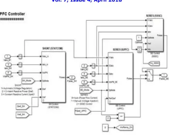
Figure 2 IUPFC Controller
When operating in UPFC mode, the magnitude of the series injected voltage is varied by varying the Sigma conduction
angle, therefore generating higher harmonic contents than the shunt converter. As illustrated in this example, when the series converter operates in SSSC mode it generates a "true" 48-pulse waveform.
ISSN (Print) : 2320 – 3765 ISSN (Online): 2278 – 8875
I
nternational
J
ournal of
A
dvanced
R
esearch in
E
lectrical,
E
lectronics and
I
nstrumentation
E
ngineering
(A High Impact Factor, Monthly, Peer Reviewed Journal)
Website: www.ijareeie.com
Vol. 7, Issue 4, April 2018
V. RESULT & DISCUSSION
Simulation
(i). Power control in IUPFC mode
Open the IUPFC GUI block menu. The GUI allows you to choose the operation mode (IUPFC, STATCOM or SSSC) as well as the Pref/Qref reference powers and/or Vref reference voltage settings . Also, in order to observe the dynamic response of the control system, the GUI allows you to specify a step change of any reference value at a specific time. Make sure that the operation mode is set to "IUPFC (Power Flow Control)".
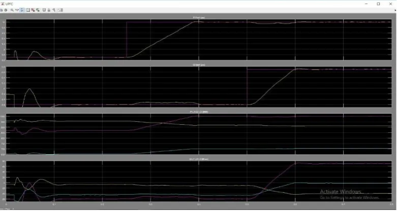
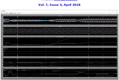
Figure 4Waveform of UPFC Mode
The reference active and reactive powers are specified in the last two lines of the GUI menu. Initially, Pref= +8.7 pu/100MVA (+870 MW) and Qref=-0.6 pu/100MVA (-60 Mvar). At t=0.25 sec Pref is changed to +10 pu (+1000MW). Then, at t=0.5 sec, Qref is changed to +0.7 pu (+70 Mvar). The reference voltage of the shunt converter (specified in the 2nd line of the GUI) will be kept constant at Vref=1 pu during the whole simulation (Step Time=0.3*100> Simulation stop time (0.8 sec). When the UPFC is in power control mode, the changes in STATCOM
reference reactive power and in SSSC injected voltage (specified respectively in 1st and 3rd line of the GUI) as are not used.
Run the simulation for 0.8 sec. Open the "Show Scopes" subsystem. Observe on traces 1 and 2 of the UPFC scope the
variations of P and Q. After a transient period lasting approximately 0.15 sec, the steady state is reached (P=+8.7 pu; Q=-0.6 pu). Then P and Q are ramped to the new settings (P=+10 pu Q=+0.7 pu). Observe on traces 3 and 4 the resulting changes in P Q on the three transmission lines. The performance of the shunt and series converters can be observed respectively on the STATCOM and SSSC scopes. If you zoom on the first trace of the STATCOM scope, you can observe the 48-step voltage waveform Vs generated on the secondary side of the shunt converter transformers (yellow trace) superimposed with the primary voltage Vp (magenta) and the primary current Ip (cyan). The dc bus voltage (trace 2) varies in the 19kV-21kV range. If you zoom on the first trace of the SSSC scope, you can observe the injected voltage waveforms Vinj measured between buses B1 and B2.
2. Var control in STATCOM mode
ISSN (Print) : 2320 – 3765 ISSN (Online): 2278 – 8875
I
nternational
J
ournal of
A
dvanced
R
esearch in
E
lectrical,
E
lectronics and
I
nstrumentation
E
ngineering
(A High Impact Factor, Monthly, Peer Reviewed Journal)
Website: www.ijareeie.com
Vol. 7, Issue 4, April 2018
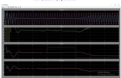
Figure 5Waveform of STATCOM Mode
In this mode, the STATCOM is operated as a variable source of reactive power. Initially, Q is set to zero, then at T1=0.3 sec Q is increased to +0.8 pu (STATCOM absorbing reactive power) and at T2=0.5 sec, Q is reversed to -0.8 pu (STATCOM generating reactive power).
Run the simulation and observe on the STATCOM scope the dynamic response of the STATCOM. Zoom on the first trace around t=0.5 sec when Q is changed from +0.8 pu to -0.8 pu. When Q=+0.8 pu, the current flowing into the STATCOM (cyan trace) is lagging voltage (magenta trace), indicating that STATCOM is absorbing reactive power. When Qref is changed from +0.8 to -0.8, the current phase shift with respect to voltage changes from 90 degrees lagging to 90 degrees leading within one cycle. This control of reactive power is obtained by varying the magnitude of the secondary voltage Vs generated by the shunt converter while keeping it in phase with the bus B1 voltage Vp. This change of Vs magnitude is performed by controlling the dc bus voltage. When Q is changing from +0.8 pu to -0.8 pu, Vdc (trace 3) increases from 17.5 kV to 21 kV.
3. Series voltage injection in SSSC mode
ISSN (Print) : 2320 – 3765 ISSN (Online): 2278 – 8875
I
nternational
J
ournal of
A
dvanced
R
esearch in
E
lectrical,
E
lectronics and
I
nstrumentation
E
ngineering
(A High Impact Factor, Monthly, Peer Reviewed Journal)
Website: www.ijareeie.com
Vol. 7, Issue 4, April 2018
Figure 6 Wave form of SSSC Mode
The initial voltage is set to 0 pu, then at t=0.3 sec it will be ramped to 0.8 pu.Run the simulation and observe on the SSSC scope the impact of injected voltage on P and Q flowing in the 3 transmission lines. Contrary to the UPFC mode,
in SSCC mode the series inverter operates with a constant conduction angle (Sigma= 172.5 degrees). The magnitude of the injected voltage is controlled by varying the dc voltage which is proportional to Vinj (3rd trace). Also, observe the waveforms of injected voltages (1st trace) and currents flowing through the SSSC (2nd trace). Voltages and currents stay in quadrature so that the SSSC operates as a variable inductance or capacitance.
VI. CONCLUSION & FUTURE SCOPE
This work deals with the control of real and reactive power in power system using MATLAB/SIMULINK. Unified Power Flow Controller (UPFC) is a shunt-series type converter used for improving power quality. The UPFC controls the real and reactive powers by varying firing angle of the rectifier and inverter. The circuit model for UPFC is developed using MATLAB/SIMULINK.
In the MATLAB simulation will operate in following modes for analyses the IUPFC:
Power control in UPFC mode
Var control in STATCOM mode
Series voltage injection in SSSC mode
ISSN (Print) : 2320 – 3765 ISSN (Online): 2278 – 8875
I
nternational
J
ournal of
A
dvanced
R
esearch in
E
lectrical,
E
lectronics and
I
nstrumentation
E
ngineering
(A High Impact Factor, Monthly, Peer Reviewed Journal)
Website: www.ijareeie.com
Vol. 7, Issue 4, April 2018
REFERENCES
[1] A. V. Naresh Babu S. SivanagarajuJawaharlal Nehru Technological University, Kakinada “Mathematical modelling, analysis and effects of interline power flow controller (IPFC) parameters in power flow studies”
[2] FACTS controllers.Electric Power Systems,” Research76(2006)824- 831, 14 Oct 2005 '
[3]R. Orizondoand R. Alves, “UPFC Simulation and Control Using the ATP/EMTP and MATLAB/Simulink Programs,” IEEE PES Transmission and Distribution Conference and Exposition Latin America, Venezuela, Aug 15- 18, 2006
[4]A. Ajami, S.H. Hosseini, and G.B. Gharehpetian, “Modelling and Controlling of UPFC
forPowerSystemTransientStudies,”ECTITransonElectricalENG.,Electronics,andcommunications,VOL.5,NO.2August 2007
[5]N. G. Hingorani, L. Gyugyi, “Concepts and Technology of Flexible AC Transmission Systems,” IEEE Press, John Wiley & Sons, 2000.
[6]V. Azbe, R. Mihalic, “Energy function for an interline power-flow controller, Electric Power Systems,” Research 79 (2009) 945–952, 16 Dec 2008
[7]C. Dufour, J. Bélanger, “Real-time Simulation of a 48-Pulse GTO STATCOM Compensated Power System on a Dual-Xeon PC using RT-LAB,” International Conference on Power Systems Transients (IPST’05) in Montreal, Canada on June 19-23, 2005 Paper No. IPST05 – 253
[8]TahaSelimUstun and SaadMekhilef, “A Quasi- resonant Soft Switching 48-pulse PWM Inverter with Closed Loop Current Control for the Realization of Static Synchronous Series
[9]Compensator (SSSC) ,” Australian Journal of Basic and Applied Sciences, 3(3): 1814-1826, 2009, ISSN 1991-8178
[10] Myung-Bok Kim, Gun-Woo Moon and Myung-JoongYoun, “Synchronous PID Decoupling Control Scheme for Dynamic Voltage Restorer against a Voltage Sag in the Power System,” 35th Annual IEEE Power Electronics Specialists Conference, pp. 1046-1051, 2004
[11]S. T. Kalyaniand G. T. Das, “Simulation of D-Q control System for a Unified Power Flow Controller,” Asian Research Publishing Network (ARPN), ISSN 1819-6608, VOL. 2, NO. 6,Dec 2007