Microspalling Process of an Explosively-Driven Metal Tin:
Experiments and Numerical Simulations
Qingzhong Li1, Peng Wang1, Guowu Ren1,*, Wentao Liu2, and Yongtao Chen1
1Institute of Fluid Physics, Chinese Academy of Engineering Physics, Mianyang, 621900, China
2Institute of Applied Physics and Computational Mathematics, Chinese Academy of Engineering Physics, Beijing, 100094, China
Abstract. Shock-induced melting phenomenon in tin material attracts considerable attention recently. Particularly, under the strong explosively loading, the shock-induced melted tin with lower strength is the weak region where the dynamic damage and fracture commonly appear, resulting in the “micro-spallation” process. In the current work, three tin targets with different thicknesses are designed to investigate such micro-spallation phenomenon of shock-loaded pure tin. A new damage model considering the melting effect is proposed and the simulated results are compared with experimental measurements for the validation.
1 Introduction
Dynamic damage and fracture phenomena in shock-loaded materials are critical issues for both basic science research and engineering applications. When the target is strongly shocked, the interaction between the shock wave loading and the reflected pulse from its free surface could generate inevitable tensile stresses inside the target. The appearance of such shock-driven tensile stresses provides the source of dynamic damage and fragmentation processes, also nominated as spallation phenomenon, for shock-loaded materials. Among numerous research works, metal tin is particularly favoured by researchers recently due to its special low melting point feature [1-8]. Previous founds [1-8] revealed that, when Sn target is subjected to shock loading, the solid tin could be partially or fully melted on compression directly or on later release. Different from the solid β-phase tin or γ-phase tin, the shock-induced
liquid tin can hardly bear the tensile stress, thus, these melted tin materials become the weak regions and provide the root of fractures for the shock-loaded target. Corresponding to the traditional spallation process for solid materials, the dynamic fragmentation phenomenon for shock-loaded tin is usually called as the “micro-spallation” process.
In the paper, we investigate the dynamic behaviour of the explosively loaded tin targets with different thicknesses via both of experimental diagnostics and numerical simulations. A thin aluminium foil is attached to the LiF window close to the free surface of the Sn target, used for capturing the interface velocity. X-ray radiography is adopted for measuring the areal density evolution of the micro-spallation. For the simulation part, based on the compatible Lagrangian hydrodynamics method [9-11], we propose a damage model considering shock-induced melting effect for simulating the dynamic
micro-spallation process. At the end of this paper, the predicted results are then compared with the experimental measurements to validate the proposed damage model.
2 Experimental setup and numerical
model
2.1 Experimental setup
Fig. 1 presents the schematic of the experimental setup used in the current study. Three circular tin targets of 99.99% purity were designed with the same diameter Φ
= 25 mm and three different thicknesses t = 4 mm, 8 mm and 12 mm, which were named by sn04, sn08 and sn12, respectively, for the sake of convenience. All of them were explosively driven by high explosives with fixed diameter Φ = 25 mm and thickness h = 30 mm.
In this paper, two groups of experiments were executed. In the first group (as depicted in Fig. 1 (a)), we electroplated a 1-m-thick Aluminium foil to the surface of the LiF window. Such thin rough Al foil realizes the diffuse reflection of the laser from Doppler Pins System (DPS) and thereby enhance the intensity of the reflected laser. The LiF window was attached to the top surface of each tin target to obtain the interface velocity, which allows us to analyse the shock loading history for tin targets.
(a) Interface velocity measurement
(b) X-ray radiography & DPS
Fig. 1. Schematic of the experimental setup.
2.2 Proposed damage model
In previous research [12], it was found that the onset shock-breakout pressure of melt-on-release for pure tin isPSB =19.5 GPa, while, if PSB≥33 GPa, the shock-loaded tin could be released to a 100% liquid state. Considering three samples investigated in the current work, we can predict that, under the same loading condition, sn04 and sn08 samples are then partially melted after shock compression, but the thick sn12 target remains solid state. In this case, we introduce a melting proportion variable DT ( 0≤DT ≤1) to represent the extent of shock-induced melting for tin targets, which writes:
(
1)
2 T mT T mT E E D E α α − − = (1)where ET is the thermal energy, EmT means the melting thermal energy derived from the modified Lindermann formula and GRAY equation-of-state [13], α is material parameter.
We assume that, when ET ≥ −
(
1 α)
EmT, the solid Sn starts to be melted. If ET reaches(
1+α)
EmT , the investigated tin target is then assumed to be fully melted.T
E and EmT take the following expressions:
0 1
µ ρ ρ= − , Tm0 is the melting temperature under
ordinary pressure, γ0 is the Gruneïsen parameter, a is a
correction factor for γ0, which gives γ γ= −0 ax.
Then, the coupling effect between the pre-defined melting proportion and the progressive damage can be expressed as:
(
)
(
)
0 0 1 1 1 c t s T Tdt K D
D λ σ β σ β − = − −
∫
(4)Based on the above expression, we can obtain the micro-spallation damage rate Dm by:
(
)
(
)
0 1 1 1 s T m T D D K D λ σ σ β β − − = − (5)Besides, the material constitutive equation and equation of state (Ptrepresents the pressure expression when the material is under tension state; Pcis the one in compression situation) are correspondingly updated as follows:
(
1)
;(
1)
m m m m
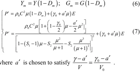
Y =Y −D G =G −D (6)
(
) (
)
(
)
(
)
(
)
2
0 0
2 0 2
0
0 2
2 3
1 2 2 2
1 1 1 2 2 1 1 1 1 t m c
P C D a E a C
P a E
S S S
ρ µ γ µ γ ρ µ µ µ γ µ µ µ µ µ µ ′ = − + + ′ + − − = + + ′ − − − − + + (7)
where a′ is chosen to satisfy 0 0 a a V V γ γ − =′ − ′ .
3 Results and discussion
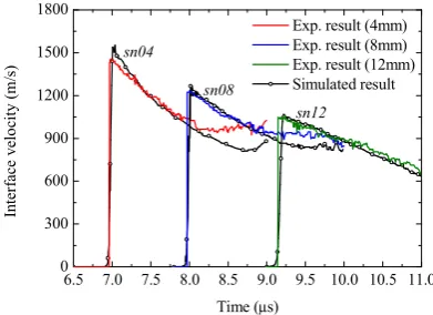
In this section, we present the simulated results based on the above damage model together with the experimental measurements. Fig. 2 shows the measured and predicted interface velocities of the investigated three tin samples using the proposed LiF window technique, with time
0s
loading, the shock-induced melting phenomenon in the thin sn04 target is the most apparent, resulting in more mount of ejected particles than other cases (as identically reflected in more broad feature of the measured free surface velocity for sn04).
6.5 7.0 7.5 8.0 8.5 9.0 9.5 10.0 10.5 11.0 0
300 600 900 1200 1500 1800
sn12 sn08
In
ter
face
v
el
oci
ty
(m
/s)
Time (µs)
Exp. result (4mm) Exp. result (8mm) Exp. result (12mm) Simulated result
sn04
Fig. 2. Measured and calculated interface velocities of three Sn samples.
(a) Free surface velocity of sn04
(b) Free surface velocity of sn08
(c) Free surface velocity of sn12
Fig. 3. Measured and calculated free surface velocities of three Sn samples.
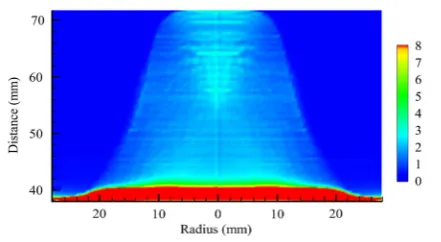
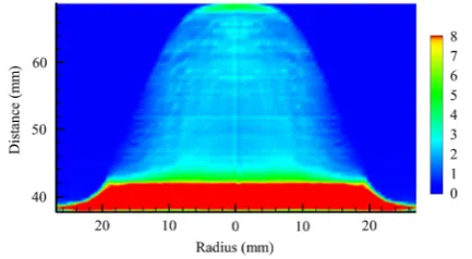
The comparisons between the measured and simulated distributions of equivalent areal density (areal cumulated thickness) are displayed in Fig. 4 to Fig. 6 for sn04, sn08 and sn12 samples, respectively.
(a) Experimental result at τ=13.2s
(c) Experimental result at τ =22.5s
(d) Simulated result at τ=22.5s
Fig. 4. Areal density results of sn04 target.
(a) Experimental result at τ=14.25s
(b) Simulated result at τ=14.25s
(d) Simulated result at τ =20.95s
Fig. 5. Areal density results of sn08 target.
It can be noticed that the profiles of the areal density distribution for all three cases are well depicted with the proposed damage model compared to the corresponding experimental founds. According to all results, it is revealed that the areal density distribution of the ejection has spatial non uniformity characteristic. In the fore head of the ejection cloud, several layers of tenuous particles are firstly ejected, which results in a low density zone.
(a) Experimental result at τ=14.4s
(d) Simulated result at τ=20.3s
Fig. 6. Areal density results of sn12 target.
Then, an approximate cylinder with moderate density is observed. While the most compact ejected tin is found appearing in the rear of the cloud. However, for more detailed feature, the proposed model still needs to be improved further in the future to obtain more close predictions to the experimental measurements and reasonably reveal the true dynamic micro-spallation process for shock-loaded tin.
4. Conclusions
In this paper, the dynamic micro-spallation process of shock-loaded tin is examined via both of experimental diagnostics and numerical modeling. A new damage model considering the shock-induced melting effect is proposed for simulating the dynamic fracture behavior of tin targets. The obtained results indicate that the proposed model provides a feasible method for studying the dynamic micro-spallation process of shock-loaded tin.
References
1. M.B. Zellner, J.E. Hammerberg, M. Grover, R.S. Hixson, A.J. Iverson, G.S. Macrum, K.B. Morley, A.W. Obst, R.T. Olson, J.R. Payton, P.A. Rigg, N. Routley, D.G. Stevens, W.D. Turley, L. Veeser,
2. J. Appl. Phys. 102 (2007)
3. T. de Rességuier, L. Signor, A. Dragon, M. Boustie, G. Roy, F. Llorca, J. Appl. Phys. 101 (2007)
4. T. de Rességuier, L. Signor, A. Dragon, P. Severin, M. Boustie, J. Appl. Phys. 102 (2007)
5. T. de Rességuier, L. Signor, A. Dragon, M. Boustie, L. Berthe, J. Appl. Phys. 92 (2008)
6. L. Soulard, Eur. Phys. J. D 50 (2008)
7. T. de Rességuier, L. Signor, A. Dragon, G. Roy, Int. J. Fracture 63 (2010)
8. L. Signor, T. de Rességuier, A. Dragon, G. Roy, A. Fanget, M. Faessel, Int. J. Impact Eng. 37 (2010) 9. Y. Liao, M.Z. Xiang, X.G. Zeng, J. Chen, Comput.
Mater. Sci. 95 (2014)
10. P.P. Whalen, J. Comput. Phys. 124 (1996)
11. E.J. Caramana, D.E. Burton, M.J. Shashkov, P.P. Whalen, J. Comput. Phys. 146 (1998)
12. C.H. Chang, A.K. Stagg, J. Comput. Phys. 231 (2012)
13. W.T. Buttler, D.M. Oró, R.T. Olson, F.J. Cherne, J.E. Hammerberg, R.S. Hixson, S.K. Monfared, C.L. Pack, P.A. Rigg, J.B. Stone, G. Terrones, J. Appl. Phys. 116 (2014)