OPTIMIZING TRAFFIC ENGINEERING IN
SOFTWARE DEFINED NETWORKING
Mouhammd Alkasassbeha,∗, Ghazi Al-Naymata, Mohammad Alauthmanb, Esra Edenatc
aKing Hussein Faculty of Computing Sciences Princess Sumaya University for technology,Jordan bDepartment of Computer Science, Faculty of information technology, Zarqa University, Jordan cDepartment of Computer Science, Faculty of information technology, mutah University, Jordan
Abstract
The digital society is an outcome of the Internet which has nearly made everything
connected and accessible no matter where or when. Nevertheless, despite the fact
that conventional IP networks are complicated and very hard to manage, they are
still widely adopted. The already established policies make the network
configura-tion/reconfiguration a complex process that reacts to errors, load, and modifications.
The prevailing networks are vertically integrated which makes things more and more
complicated: Data planes and control are strapped together. Software-defined
network-ing is a model that is meant to solve this issue by splittnetwork-ing the vertical integration and
detaching the networks control logic from the implicit routers and switches; this could
be achieved by reinforcing centralization of network control and making the network
programmable. In this work, we worked to implement MPLS networks with SDN, to
enhance the traffic engineering over the network, and to minimize the network delay
and latency, with minimum cost using three of the different SDN networks. The
exper-iment results showed the advantage of the proposed approach for reducing the network
delay, comparing with previous studies. Where the average of network delay in our
approach reaches to 3.01 milliseconds.
Keywords: Software-Defined Networking (SDN), Traffic Engineering
∗Corresponding author
Email addresses:[email protected](Mouhammd Alkasassbeh),
[email protected](Ghazi Al-Naymat),[email protected](Mohammad Alauthman),[email protected](Esra Edenat)
(TE),Multiprotocol Label Switching (MPLS), Load Balancing, Quality of Service
(QoS),Bat Algorithm, Dijkstra.
1. Introduction
The allotted control and transport network protocols operating inside the routers
and switches are the essential technologies that enable data, in the frame of digital
packets, to move around the world. Despite their broad usage, regular IP networks
are complicated and difficult to handle [1, 2]. To express the required high-level
net-5
work policies, network operators demand to configure every single network device
independently applying low-level and often vendor-specific commands. In addition to
the configuration complexity, network environments have to handle the dynamics of
faults and adapt to load changes. Automatic reconfiguration and response devices are
virtually missing in existing IP networks. Implementing the needed policies in such a
10
dynamic environment is consequently extremely challenging.
To make it even more difficult, prevailing networks are also vertically integrated.
The control plane (that decides how to handle network traffic) and the data plane (that
forwards traffic according to the decisions made by the control plane) are strapped
inside the networking devices, decreasing flexibility and preventing modification and
15
development of the networking infrastructure. The transition from IPv4 to IPv6, began
more than a decade ago and still largely inadequate, bears witness to this challenge,
while in fact, IPv6 served merely a protocol update. Due to the passivity of current IP
networks, a novel routing protocol can take five to ten years to be completely produced,
estimated, and used. Furthermore, a clean-slate plan to change the Internet architecture
20
(e.g., replacing IP) is viewed as a daunting mission not possible in practice [3, 4].
Finally, this situation has increased the capital and operational charges of operating an
IP network. Software-defined networking (SDN) is a novel networking paradigm that
provides the facility to reduce the constraints of available network infrastructures [5].
1.1. Software-Defined Networking (SDN)
25
As stated before, SDN is a new networking paradigm that promises to reduce the
Figure 1: SDN architecture [1]
by detaching the networks control logic from the underlying routers and switches that
assist the traffic. Second, by separating the control and data planes, network switches
grow simple forwarding devices and the control logic is realized in a logically
central-30
ized controller, simplifying policy implementation and network reconfiguration and
development [6]. A detailed design of this architecture is presented in Fig. 1. It is
necessary to indicate that a logically centralized model does not assume a physically
centralized system [7]. In fact, the need to guarantee sufficient levels of performance,
scalability, and reliability would hinder such solution. Alternatively, SDN network
35
designs resort to physically distributed control planes [7].
SDN enables a network to be programmed so that its function can be adjusted
ac-tively on call and in a fine-grained behavior. It is a unique networking model, where
the control plane and the data plane are departed. The idea behind SDN is to simplify
network management and allow change, i.e., to promote and use new network
appli-40
cations and services easily, also to run and optimize network performance throughout
high-level policy enforcement [8].
at Stanford University, USA [9]. As originally defined, SDN indicates to a network
architecture where the forwarding state in the data plane is handled by a remotely
con-45
trolled plane separated from the former. On many occasions, the networking
manufac-turing has changed from this fundamental view of SDN by transferring to anything that
includes software as being SDN. In addition, an SDN can be described as a network
architecture as following:
1. The control and data planes are separated. Control functionality is eliminated
50
from network devices that will become easy (packet) forwarding components.
2. Forwarding decisions are flow based, rather than destination based. Flow is
widely defined by a collection of packet field values serving as a filter
crite-rion and a collection of directions [9]. In the SDN/OpenFlow fashion, flow is a
course of packets between a source and a destination. All packets of a flow get
55
the same service policies at the forwarding devices [10, 11].
The flow concept allows uniting the behavior of various kinds of network
de-vices, including routers, switches, and middle-boxes. Flow programming allows
unique flexibility, bounded only to the capabilities of the implemented flow
ta-bles [2].
60
3. Control logic is driven to an external entity, the so-called SDN controller or
Net-work Operating System (NOS). The NOS is a software program that Net-works on
commodity server technology and presents the necessary resources and
abstrac-tions to promote the programming of forwarding devices based on a logically
centralized and abstract network view. Its objective is consequently related to
65
that of a conventional operating system.
4. The network is programmable through software applications operating on top of
the NOS that interacts with the underlying data plane devices. This is a primary
aspect of SDN, viewed as its principal value proposition.
A notable outcome of the SDN principles is the separation of concerns presented
70
between the description of network policies, their use in switching hardware, and the
forwarding of traffic. This separation is core to the sought flexibility, splitting the
offer new abstractions in networking, simplifying network management and facilitating
network development and modification.
75
1.2. TRAFFIC ENGINEERING
A main difficulty with underlying communication network is the dynamic essence
of the network applications and their environment. This means that the performance
el-ements of the conveyed data flows, like Quality of Service (QoS), may differ over time.
The applications run in a broad span of environments. For the applications to function
80
efficiently, the underlying network should be quite flexible to dynamically change in
response to any modifications in the application requirements and their environment.
The available programs are either based on static or overprovisioned overlay networks
or need the applications to adapt following the network performance [8].
An outstanding action to approach this difficulty is by Traffic Engineering (TE),
85
which is the manner of interpreting the network state, predicting and adjusting the
for-warded data load over the network resources. It is a procedure employed to readjust
the traffic routing to the settings in the network state. The purpose of TE is to evolve
network performance and QoS by effective management of resources, which can
de-crease operation charge too. The QoS procedures allocate the available resources to
90
the prioritized traffic to bypass congestion for this traffic. However, these procedures
do not afford extra resources to the traffic that demands QoS. The conventional routing
techniques do not offer any mechanism to allocate network resources optimally [10]
[12].
To approach this problem, the research community commenced managing traffic
95
engineering and suggested innovative ideas to promote network robustness in response
to the expansion of traffic demands. Traffic engineering decreases the service
degra-dation due to congestion and failure. Moreover, to optimize these heterogeneous
net-works, both traditional networks and SDN netnet-works, some Traffic Engineering (TE)
systems have been proposed. Most are based on tweaking wide range TE and routing
100
mechanism, such as ECMP, IS-IS, and MPLS [8].
In this work, a hybrid approach scenario had been built for using the MPLS to get
fo-cused to minimize the network delay and cost for sending packets through the network.
The proposed scenario has aimed to find the shortest path for the destination between
105
the sender node and a receiver node, we used the Dijkstra and bat algorithm for
send-ing packets with the best traffic density and minimum network delay. The experiment
results show the advantage of the proposed approach for reducing the network delay
comparing with other researchers’ works as it will be shown in the findings discussion
section.
110
In the next section, we present a review of existing traffic engineering techniques.
The proposed solution is explained in Section 3. Section 4 provides the experiment
results and findings discussion. Finally, the conclusion is summarized in Section 5.
2. Review Of Existing Traffic Engineering Techniques
In SDN networks the controller can actively improve the network state, for
exam-115
ple, in conventional networks, the link cost for routing protocols such as IS-IS are held
static for a long time. If congestion occurs in the network, it may lead to inadequate
de-livery of data till the link costs are adjusted, or the problem is settled. Nevertheless, in
SDN these values can be adjusted more dynamically to adapt to the changes. More
pro-ductive routing mechanism can be implemented, or the present routing protocols can be
120
adjusted so that they can change dynamically as per network state to improve resource
utilization, prevent failure and congestion, and promote QoS. With the improvements
in SDN many TE techniques have been presented by the research community.
MiceTrap includes the end-host flow detection to manage mice-flows and handles
OpenFlow group table to collect the incoming mice-flows for each end [13]. The
au-125
thors assume that TE mechanism, which manages elephant-flows (EFD), can create
congestion to mice-flows, i.e., short-lived flows. Also, the resources should be
allo-cated according to flow values. Running mice-flows applying ECMP and providing
preference to elephant flows can degrade QoS. MiceTrap architecture consists of
end-host elephant flow detection module, multi-path aggregates performed in OpenFlow
130
switch, and a controller. It uses the kernel-level layer (KLL) approach to identify the
given period the buffer passes the designated threshold. This decreases the rules for TE
because if each mice-flow is managed by a specific flow rule, it will lead to a bottleneck
and restrict the scalability. The benefit of employing group table is that it saves
band-135
width as one single group message can refresh a set of flows when the traffic allocation
is changed. It applies a weighted routing algorithm which forwards aggregated traffic
into various paths by weighing the current network load while calculating the routes
[13].
Farhadi et al. [14] present a tag-based classification architecture, where the switches
140
tag the packets based on the application classes. This way the network operator can
im-plement various policies for each of the application classes. The tag is also employed
as an identifier for matching the packets which decrease the matching overhead.
Af-ter a tagged packet is conveyed to the destination edge switch, the switch eliminates
the tag and displays the needed actions, if there is any action, and forwards the packet
145
to the destination host. The empirical result confirms that method is 3 ms faster than
the matching applying hash-based approaches like OpenFlow field matching, and
de-grades processing overhead. To work out the backward compatibility, unlike MPLS,
the tag is added to the end of the packet rather than of its middle [14]. This way, if
the changeable length packet is confirmed, there is no need for whole packet parsing.
150
Oppositely, the whole packet should be parsed. The downside of this approach is that
it needs modifications in the switch internal by adding a new API to the switch data
plane.
Zafar et al. [15] examined how to unite application awareness with SDN networks
and how to categorize traffics with high accuracy. A framework named Atlas is
pre-155
sented, which is able of organizing the traffic in the network and implementing higher
layer policies. The given framework applies a C5.0 ML tool to classify the flows based
on the application types. It reveals 94% accuracy. The Atlas framework can classify
every precise application. It can classify every VoIP application specifically rather than
classifying them as a common VoIP flows. So framework should be scalable so the
160
application detection and implementing application-aware policy is arranged in a soft
and consecutive manner. The deployment of this model needs the users to install
every application [15].
Enhancing network services and security can be achieved by performing network
165
traffic classification identifying applications, which is one of the primary components
of network operations and management. For example, Al-Naymat et al. [12]
intro-duced a real testbed data had been collected from five different VoIP and Non-VoIP
applications that are used by the majority of the Internet community. A classification
step is performed using off-the-shelf machine learning techniques, specifically Random
170
Forest J48, meta.AdaBoost (J48) and MultiLayer Perceptron to classify the traffic. their
results show that using the new features can dramatically improve the true positive
ra-tio by up to 98% and this is a significant outcome towards providing accurate traffic
classification.
To approach TE in SDN, Dinh et al. [16] proposed a multipath-based forwarding
175
TE technique called MSDN-TE. The purpose of this method is to transmit the traffic
in a way that bypasses congestion on any link in the network. It dynamically decides
on the best possible shortest paths and forwards the incoming traffic. It also collects
network state information and examines the actual paths load to deliver the flows on
many paths. The MSDN-TE is a module which increases OpenDayLight controller
180
Authors of [17] introduced the CIP and CDP schemes to obtain fast failure recovery
while reducing the interruption of the SDN controller, reducing the memory
require-ment in the controller, and decreasing the creation of the control traffic in the recovery
operation. Based on the flow grouping procedure, the suggested schemes could
consid-erably decrease recovery time while also reducing memory requirement in switching
185
components. In the performance assessment, it has been recognized that the suggested
recovery schemes have attained the 99% decrease in flow storage for other path setup
employing VLAN tagging and decreased the failure recovery time up to 4 ms and 20
ms, satisfying 50 ms total failure recovery time needed in the employed networks.
Tajiki et al. [18] presented a new resource reallocation algorithm, termed QNR.
190
This algorithm reschedules the network in a style that requires the least overhead in
forwarding table updates. Since QNR applies the SDN facilities for resource
reallo-cation, it is fit for networks with dynamic traffics in which the resource partitioning
expressed in the formation of binary linear programming. To work out the
correspond-195
ing optimization problem, a scheme was introduced. The performance of the suggested
scheme was compared with the shortest-path by three metrics 1) SFTC), 2) delay, and
3) packet loss. In all of the test forms, the SFTC and delay increased more than 90
and 60 times, sequentially. Additionally, to completely judge the influence of QNR on
network throughput, the packet loss was compared in a simple topology which proved
200
a significant reduction in the packet loss. Eventually, QNR and RQNR were compared
concerning time complexity view. In this way, it is noted that the suggested
forward-ing table procedure (which is used in RQNR) reduces the overhead of FTs update by
reducing the number of dynamic flows (the forwarding table rates range between 15%
and 90%) [18].
205
Sinha et al. [19] proposed hybrid model where MPLS and SDN models
synchro-nize and harmosynchro-nize together to allow the stable transition. Particularly, the author
employs the regular MPLS data plane concurrently with an uncomplicated and
exten-sible control-plane based on OpenFlow and SDN to develop a hybrid operation model.
The traffic is divided using forwarding equivalence classes at the ingress router, which
210
can be updated via a centralized controller using OpenFlow. This model can achieve
conflict-free separation of centralized and decentralized controls. Also, it has been
confirmed that a centralized controller can provision traffic flows better compared to
decentralized based programs using MPLS. Hence, this model presents a better option
for the stable transition of a legacy network to a SDN network.
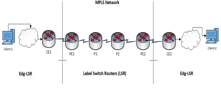
215
Kitsuwan et al. [20] introduced a model to decrease both the number of constant
flow entries and the number of configuration messages from the controller, described as
a hybrid permanent flow (HPF) model, in SDN. In this model, switches in the network
are broken into different regions. Two MPLS tags (outer and inner) are selected for a
packet routing. The outer tag steers a packet from a source switch to an edge switch
220
in its destination region. The inner tag navigates the packet from the edge switch to
the destination switch in the local region. A mathematical formulation to define a
group of switches in every region so the total number of constant flow entries in the
network is reduced. The NSF topology and a sample topology was employed. In
the NSF topology, the switches are assorted into three regions. The interpretation of
the number of flow entries for a sample topology was offered. The performance of
the HPF plan was examined. Results from the examination showed that 70% of the
number of constant flow entries and 80% of the number of configuration messages had
decreased in comparison with the traditional schemes. These decreases require a lower
bandwidth in the control plane, a lower process of CPU in the controller, and a smaller
230
TCAM memory size in every switch.
Kosugiyama et al. [21] used a heuristic approach to aggregate flows for operating
application flows in SDN. The recommended approach sights to reduce the number of
flows while every flow contents its permissible delay. It was assessed in some traffic
conditions, and simulation outcomes proved that the plan considerably exceeds simple
235
routing by employing the aggregation. The authors formed a flow aggregation problem
without link bandwidth. In a real network, though, flows that require more bandwidth
and exceed link bandwidth cause packet loss as a result of QoS control. Therefore, the
authors assessed the suggested method in a more realistic model acknowledging link
bandwidth. The proposed method decreased the number of flows more efficiently in
240
a network with high link density. Still, the method is not very efficient in a network
such as a tree model where the route of flows can be uniquely defined. Nevertheless,
real networks based on tree models have bypass links for load balancing or decreasing
delivery delay.
Amaral et al. [22] SDN TE architecture that reacts to regular scaling issues that
245
occur in SDN optimization based TE systems. The authors noted how an architecture
based in a logically hierarchical control plane is befitted for a greater number of
sce-narios and how TE in such an architecture relies only on the pathfinding algorithm and
the way traffic is allotted among paths. Many algorithms for pathfinding and traffic
distribution can be utilized in the suggested architecture, and in this work, the results
250
of simulations point out that some network utilization gains can be accomplished using
simple shortest paths joined with the use of betweenness centrality for traffic
distri-bution. The use of centrality over shortest paths bounds the gains, and in topologies
where there is a small number of similar cost paths, the performance is slightly better
than ECMP.
255
cloud in SDN. The recommended scheme examined in SINET5. This network can
di-minish the latency between users and improve the TCP throughput. Reliable MPLS-TP
paths were located to be switched within 50 msec in a field test. An on-demand
con-troller was employed to be able to cooperate with users through a Web-based interface
260
and cloud services via a REST interface. Additionally, the auto-healing time of a VNF
was found to be as short as 30 seconds.
3. Hybrid Technique for Optimizing Traffic Engineering
When clients want to send its packets through MPLS network, these packets will
arrive at the edge switch with no matching flow rule, the switch asks for detailed
infor-265
mation and orders from the controller. The controller’s role is to decide on the proper
path for this packet and the other matching packets in the network; the controller also
generates an equal label and installs it in the switches on the packet’s path. This section
presents the methodology of our proposed approach, that will be used for the traffic
en-gineer measurement using MPLS in the SDN network. In this paper, we will build a
270
hybrid approach for calculating the needed amount of traffic engineering for each of
sender node and receiver node over the network. We used each of Bat and Dijkstra
algorithms in our proposed method. Where bat algorithm used for determining the
to-tal cost for sending a packet from customer edge to another using different parameters
(bandwidth, available capacity, propagation delay, and packet size). While Dijkstra
al-275
gorithms used to select the appropriate candidate of shortest path, which will be used
Figure 2: Shortest Path
The main idea of the proposed approach is to find the shortest destination between
sender edge of the client, and the receiver edge of another client through the MPLS
network. Customer edge (CE) is a special router used only by the client, and connected
280
directly with provider edges (PE) in the SDN network. Where customer edge can use
the IP methods only, and can’t use the MPLS settings and configuration, while provider
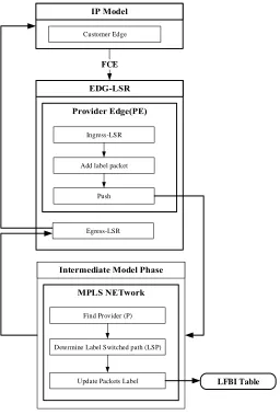
edges are working as half IP, and half MPLS. Fig. 3 represents the general framework.
Figure 3: General framework
In this paper, the proposed approach aims to find the Label-Switched Path (LSP)
between two customer edges, where LSP describe the destination path for the packets
285
Fig. 4 shows the main phases of our research, where the proposed approach
in-cludes each of IP model phase, Edge-LSR phase, and intermediate model phase.
Customer Edge
Ingress-LSR
Add label packet
Push
Egress-LSR
Find Provider (P)
Determine Label Switched path (LSP)
Update Packets Label FCE
LFBI Table
Figure 4: Our Model Phases
3.1. IP Model
Each router performs an IP lookup (routing), determines a next-hop based on its
290
next-hop. Forwarding and pop for every router, each making its own independent routing
decisions, until the final destination is reached. In the proposed approach, we will
use the IP model phase to connect traditional IP networks with the label switching in
MPLS. IP model phase is considered as the both of initial process, and the final process
295
in our proposed approach. The router in this phase uses only the IP mode, and cant use
MPLS settings. The initial process is started when the client sends packets through
customer edge (CE1), to another client (CE2), the packets are known as Forward Error
Correction (FEC), which mean the group of packets from sender router (CE) to the
service provider edge’ router (PE). While the final process is finished when IP packets
300
reach to the receiver customer edge (CE2).
3.2. Edge-LSR Phase
The second phase in the proposed system is the Edge-LSR phase. The routers in
this phase receive the IP packets (FEC) from the previous phase using Ingress-LSR
routers. Ingress-LSR routers working to receive the IP packets, then adding the label
305
for this packets, and finally forwarding this packets using push label process into a
destination for the Intermediate Model phase. After Intermediate Model phase is done,
the label packets reach to the Egress-LSR routers, this routers working to remove labels
over the packets, and send it to out the MPLS mode into IP routers (customer edges).
3.3. Intermediate Model Phase
310
This is the last phase in the proposed system, and considers as the most important
phase, because it’s working as the controller over the network, and manage the optimal
traffic flow and traffic engineering. The routers in this phase using only MPLS settings
(Label Switch Router (LSR), and not connected directly with IP routers (CE), these
routers depend on the label only for packet exchange. The proposed approach uses
315
the intermediate model phase to determine label switched path (LSP) in the MPLS, its
identify the providers (P) over the destination. In this phase, the label packets will be
updated for every router, the values of the updated label will be saved temporarily in
3.4. Optimal Traffic Flow & Traffic Engineering
320
Software Defined Networking (SDN) is an emerging paradigm that is expected to
revolutionize computer networks. In the proposed approach, we will implement the
SDN network using a topology graph G (V, E), where V is a set of switch nodes in the
network, and E is the set of links between switches.
In the first, we will find the shortest path (P) between sender node, and end node,
325
using Dijkstras algorithm. The shortest-route problem using Dijkstras algorithm
de-termines a route Eiof minimum weight connecting two specified vertices, source and
destination, in a weighted graph (digraph) in an SDN network [24]. The aim of using
Dijkstras algorithm is to find theith links (Ei) in the network graph with minimum
weight.
330
Dijkstra is a Greedy based algorithm, and it solves the different sources for the
shortest path problems, its require global information of the network [25]. Dijkstra
al-gorithm used in different applications like, Robot path planning [26], Logistics
Distri-bution Lines [2], and Link-state routing protocol [27]. The time complexity of Dijkstra
isO(|E|+|V|Log|V|).
335
After determining the shortest path P in the network, Bat algorithm will be used to
calculate the minimum cost for the distance path. The cost will be affected from the
packet size(S), because it effects on the different parameters, like: bandwidth(Bw),
latency(L), processing time(P t), and propagation time. To calculate the available
bandwidth on a given path P, we will assume the capacity(Ci)is known for every link
340
in the path, the Equation (1) calculates the related available capacity(Ai):
Ai=Ci−Bi (1)
Where theBiis current bandwidth load. Then we poll the counters in the SDN
switches and calculate the current loadBiat the timeT using Equation (2):
Bi(t) = (ni(t)−ni(t−T))
T (2)
(1) and (2), the available bandwidth on a given pathPfor each Eiwill be:
345
BW p=M IN(ai) (3)
Propagation delay is the time for one bit to propagate from source to destination at
propagation speed of the link, Equation (4) calculate the total of propagation time:
P ropagationdelay=F ST +LM D+QD+N P D (4)
Where FST is the frame serialization time (transmission time), LMD is the link
media delay, QD is the queuing delay, and NPD is the node processing delay.
F ST = S
R (5)
LM D= Ei
P d (6)
350
QD= Q
R (7)
WhereRis the link data rate (bits/second),S is the packet size (bits), P dis the
processing delay, and theQis queue depth (bits). To calculate final delay(f d)in the
proposed network, we will find the packet processing time (ppt), which it’s the time
elapsed between the arrival packet in queue, and the time of packet to processed.
f d=ppt1 +tt+tq+tp+ptt2 (8)
wherettis the transmission time (serialization time), tq is the queuing delay,tp
355
is the propagation time,ppt1is source distance in the shortest pathP, andppt2is the
final distance in the same pathP. According to all of the above Equations, the final cost
in the distance pathP for the proposed network will be calculated using the proposed
formula (9):
F inalCost= (tp∗f d)
The optimization of traffic engineering in the SDN with MPLS for different path
360
between nodes, can be calculated by the Equation below:
A=(C∗H)
T (10)
WhereA: traffic density,C: number of calls arrivals during timeT, andH: average
holding time.
3.5. Bat Algorithm
Optimization problems are very common to be found in many different applications
365
[28], in the proposed approach, Bat algorithm is used and extended to solve
multi-objective optimization problems. The proposed multi-multi-objective bat algorithm (MOBA)
is first validated against a subset of test functions [29], and then applied to solve
multi-objective design problems, in our approach, it used for selecting shortest distance with
minimum cost distance in the SDN network. We are looking for efficiently results for
370
the proposed algorithm using Micro-bats type of bat, which depends on echolocation.
4. Experiment Results
We conducted four groups of experiments according to the size of request (200,
300, 400, 500) bytes. Each group of experiments are divided into three blocks
accord-ing to the number of nodes in the network (30, 50, and 70) with 65 links in each
net-375
work. We added new factors for the results, such as total cost, shortest path, network
delay, queue delay, and bandwidth. The Table 1 shows the groups of experiments.
Moreover, We applied each group of experiments 37 times on the different cases of
source nodes.
4.1. Experiment Example
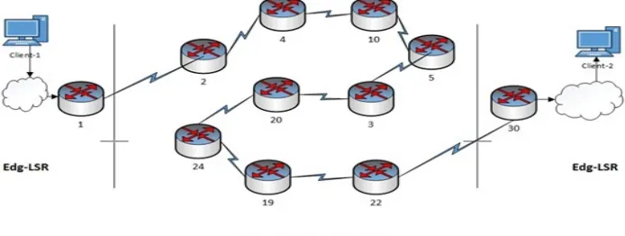
380
According to the EXP 1, the shortest path for sending 200 bytes of data from the
source (node 1) to the destination (node 30) will be shown in Figure 5. The Dijkstra’s
algorithm finds the best shortest path from (node 1) to (node 30)which is [2, 4, 10, 5,
3, 20, 24, 19, 22]. Another parameter will be calculated according to bat algorithm is
the network latency (final delay)which is equal to 0.564 milliseconds, and the needed
Table 1: The list of experiment groups
Experiment Request size (bytes) Number of Nodes
EXP 1 200 30, 50, 70
EXP 2 300 30, 50, 70
EXP 3 400 30, 50, 70
EXP 4 500 30, 50, 70
cost for sending 200 bytes of packets through the network from node to other till the
destination is 0.0089 call/second , while the available capacity is 479.32 Mbps.
Figure 5 shows how the sending packets through the MPLS network with SDN
from the source node (node 1). Then, the packets will move from IP model to the label
model, and the network will determine the next node (receive node). In the previous
390
example, node 2 called Ingress-LSR, and it will receive the packets from node 1, node
2 is working with half IP and half label technique. Each node in the shortest path [4,
10, 5, 3, 20, 24, 19] will be working only with Label technique, and they called LSR
nodes. While the node 22 is working with half IP technique and half label, it’s called
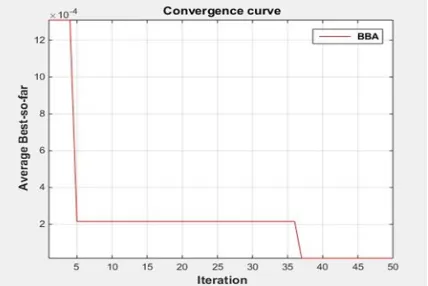
Egress-LSR. The For the bat algorithm Figure 6 shows how it ran with iteration equal
395
50.
Figure 6: Running Bat Algorithm
4.2. Results and discussion
We calculate the average of the traffic density for each experiment according to
Equation (10). In the previous example, the traffic density for the selected path is equal
62.06.
400
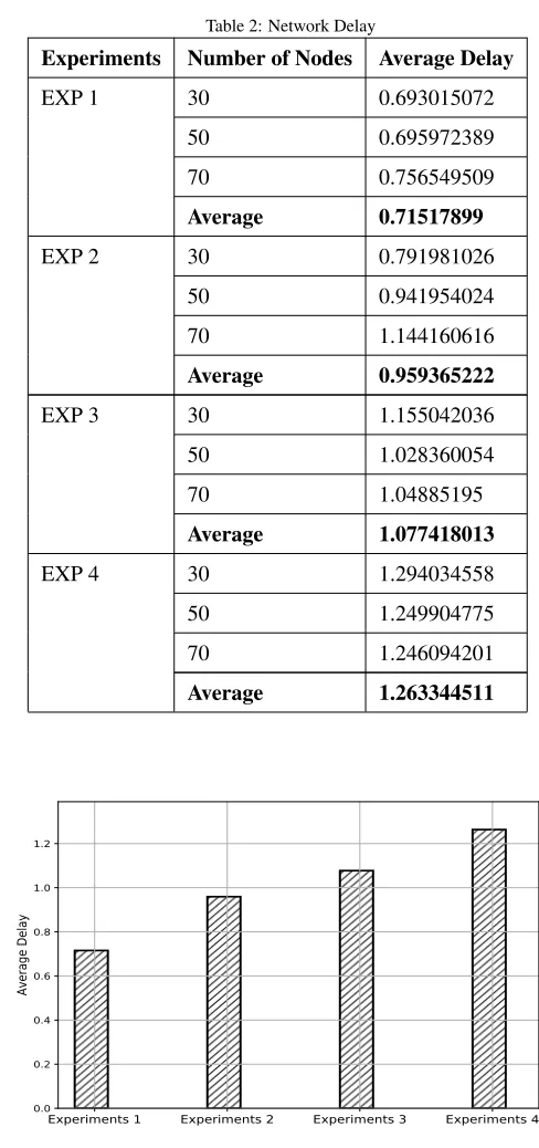
4.2.1. Network Delay
Network delay; is one of the most important parameters in the proposed approach,
we tried to reduce the delay values of the network comparing with previous studies.
The Table 2 shows the details for the maximum delay over all links in all experiments:
Figure 7 below shows the total average of maximum delay over all links in four
405
experiments.To compare the final delay in the proposed approach with the previous
studies, we will compare that using the same data set for the Agarwal et al. [30] as
shown in Figure 8, which contain of 15 node topology, We can notice the difference
of two results between the proposed approach with other approaches for each
experi-ments, which consider as the positive factor for the proposed approach.
Table 2: Network Delay
Experiments Number of Nodes Average Delay
EXP 1 30 0.693015072
50 0.695972389
70 0.756549509
Average 0.71517899
EXP 2 30 0.791981026
50 0.941954024
70 1.144160616
Average 0.959365222
EXP 3 30 1.155042036
50 1.028360054
70 1.04885195
Average 1.077418013
EXP 4 30 1.294034558
50 1.249904775
70 1.246094201
Average 1.263344511
Experiments 1 Experiments 2 Experiments 3 Experiments 4 0.0
0.2 0.4 0.6 0.8 1.0 1.2
Average Delay
Experiments 1 Experiments 2 Experiments 3 Experiments 4 Experiments 5
0.0 0.5 1.0 1.5 2.0 2.5 3.0 3.5 4.0
Average Delay
Propsed Approach Agarwal et al.,2013
Figure 8: Comparison Average Delay Over All Links (All Experiments)
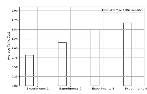
4.2.2. Traffic Density
For the Traffic density, the experiment results show the traffic density for all
exper-iments, Figure 9 below shows the total traffic density for the four experiments.
Experiments 1 Experiments 2 Experiments 3 Experiments 4
0.00 0.25 0.50 0.75 1.00 1.25 1.50 1.75 2.00
Average Taffic Cost
Average Taffic density
Figure 9: Experiments Traffic Density (bps)
We can notify the increasing value of traffic density with maximum packets, which
mean the flexibility of the proposed approach for each of big networks and the huge
packets. The average of density cost for all experiments is 70.03 bps.
4.2.3. Traffic Cost
Table 3 shows the details of the traffic costs for all experiments:
Table 3: Traffic Cost
Experiments Number of Nodes Traffic Cost
EXP 1 30 0.272733464
50 0.238619452
70 0.306838191
EXP 2 30 0.301865492
50 0.327923355
70 0.52017084
EXP 3 30 0.635195344
50 0.479264822
70 0.389239157
EXP 4 30 0.424216318
50 0.62814365
70 0.621184828
We also can notify the increasing value of traffic cost with the maximum
pack-ets, and the positive relationship between traffic cost and traffic density. Where the
420
average of traffic cost for all experiments is 1.286 Mbps. This positive relationship
be-tween average cost and traffic density is reinforced our methodology for selecting the
best shortest path with minimum cost, and show how traffic engineering affected by a
number of nodes between source nodes and distance nodes. Finally, the increasing of
packet size between nodes in the MPLS need more cost and traffic density. However,
425
this increasing provides a higher value of the bandwidth in the network, as it shown in
Experiments 1 Experiments 2 Experiments 3 Experiments 4
0 200 400 600 800 1000 1200 1400 1600
Available Bandwidth
Available Bandwidth
Figure 10: Experiments Available Bandwidth
5. Conclusion
Finally, we built a new scenario that considered as a hybrid approach for using
the MPLS to get more effectively network for transmitting a huge traffic amount in
430
Software-defined networking. In our approach, we focused to minimize each of
net-work delay and the needed cost for sending packets through the netnet-work, and to
cal-culate the maximum value of traffic density over the network. The proposed scenario
is aimed to find the shortest path for the destination between the sender node and a
receiver node, we used the Dijkstras algorithm to find the best path (shortest) between
435
a list of candidate paths. In the other hand, we used bat algorithm to find each of the
needed cost for sending packets with the best traffic density, with minimum network
delay.
We conducted four experiments according to the size of requests between nodes
(200, 300, 400, and 500 bytes), where each experiment was run on three different
440
networks, 30 nodes, 50 nodes and 70 nodes respectively. The experiment results show
the advantage of the proposed approach for reducing the network delay, comparing with
Agarwal et al.[30] study. Where the average of network delay in their study reach to
milliseconds. The results show the sending of packet size between nodes costs more
445
that of the traffic density when the increases of packet size. However, the increasing of
traffic density and cost are providing a higher value of the bandwidth in the network.
[1] W. Xia, Y. Wen, C. H. Foh, D. Niyato, H. Xie, A survey on software-defined
networking, IEEE Communications Surveys & Tutorials 17 (1) (2015) 27–51.
[2] Q. Yan, F. R. Yu, Q. Gong, J. Li, Software-defined networking (sdn) and
dis-450
tributed denial of service (ddos) attacks in cloud computing environments: A
survey, some research issues, and challenges, IEEE Communications Surveys &
Tutorials 18 (1) (2016) 602–622.
[3] H. Farhady, H. Lee, A. Nakao, Software-defined networking: A survey, Computer
Networks 81 (2015) 79–95.
455
[4] Z. Qin, G. Denker, C. Giannelli, P. Bellavista, N. Venkatasubramanian, A
soft-ware defined networking architecture for the internet-of-things, in: Network
Op-erations and Management Symposium (NOMS), 2014 IEEE, IEEE, 2014, pp.
1–9.
[5] K. Kirkpatrick, Software-defined networking, Communications of the ACM
460
56 (9) (2013) 16–19.
[6] H. Kim, N. Feamster, Improving network management with software defined
net-working, IEEE Communications Magazine 51 (2) (2013) 114–119.
[7] S. Jain, A. Kumar, S. Mandal, J. Ong, L. Poutievski, A. Singh, S. Venkata, J.
Wan-derer, J. Zhou, M. Zhu, et al., B4: Experience with a globally-deployed software
465
defined wan, in: ACM SIGCOMM Computer Communication Review, Vol. 43,
ACM, 2013, pp. 3–14.
[8] M. R. Abbasi, A. Guleria, M. S. Devi, Traffic engineering in software defined
net-works: A survey, Journal of Telecommunications and Information Technology (4)
(2016) 3.
[9] D. Kreutz, F. M. Ramos, P. E. Verissimo, C. E. Rothenberg, S. Azodolmolky,
S. Uhlig, Software-defined networking: A comprehensive survey, Proceedings of
the IEEE 103 (1) (2015) 14–76.
[10] I. F. Akyildiz, A. Lee, P. Wang, M. Luo, W. Chou, A roadmap for traffic
engi-neering in sdn-openflow networks, Computer Networks 71 (2014) 1–30.
475
[11] R. Mu˜noz, R. Vilalta, R. Casellas, R. Mart´ınez, F. Francois, M. Channegowda,
A. Hammad, S. Peng, R. Nejabati, D. Simeonidou, et al., Transport
net-work orchestration for end-to-end multilayer provisioning across heterogeneous
sdn/openflow and gmpls/pce control domains, Journal of Lightwave Technology
33 (8) (2015) 1540–1548.
480
[12] G. Al-Naymat, M. Al-Kasassbeh, N. Abu-Samhadanh, S. Sakr, Classification of
voip and non-voip traffic using machine learning approaches., Journal of
Theo-retical & Applied Information Technology.
[13] R. Trestian, G.-M. Muntean, K. Katrinis, Micetrap: Scalable traffic engineering
of datacenter mice flows using openflow, in: Integrated Network Management
485
(IM 2013), 2013 IFIP/IEEE International Symposium on, IEEE, 2013, pp. 904–
907.
[14] H. Farhadi, A. Nakao, Rethinking flow classification in sdn, in: Cloud
Engineer-ing (IC2E), 2014 IEEE International Conference on, IEEE, 2014, pp. 598–603.
[15] Z. A. Qazi, J. Lee, T. Jin, G. Bellala, M. Arndt, G. Noubir, Application-awareness
490
in sdn, in: ACM SIGCOMM computer communication review, Vol. 43, ACM,
2013, pp. 487–488.
[16] K. T. Dinh, S. Kukli´nski, W. Kujawa, M. Ulaski, Msdn-te: Multipath based
traf-fic engineering for sdn, in: Asian Conference on Intelligent Information and
Database Systems, Springer, 2016, pp. 630–639.
495
[17] P. Thorat, S. Jeon, H. Choo, Enhanced local detouring mechanisms for rapid and
lightweight failure recovery in openflow networks, Computer Communications
[18] M. M. Tajiki, B. Akbari, N. Mokari, Optimal qos-aware network reconfiguration
in software defined cloud data centers, Computer Networks 120 (2017) 71–86.
500
[19] Y. Sinha, S. Bhatia, V. S. Shekhawat, G. Chalapathi, Mpls based hybridization in
sdn, in: Software Defined Systems (SDS), 2017 Fourth International Conference
on, IEEE, 2017, pp. 156–161.
[20] N. Kitsuwan, S. Ba, E. Oki, T. Kurimoto, S. Urushidani, Flows reduction scheme
using two mpls tags in software-defined network, IEEE Access 5 (2017) 14626–
505
14637.
[21] T. Kosugiyama, K. Tanabe, H. Nakayama, T. Hayashi, K. Yamaoka, A flow
ag-gregation method based on end-to-end delay in sdn, in: Communications (ICC),
2017 IEEE International Conference on, IEEE, 2017, pp. 1–6.
[22] P. Amaral, P. F. Pinto, L. Bernardo, F. Silva, Sdn based traffic engineering
with-510
out optimization: A centrality based approach, in: Communications (ICC), 2017
IEEE International Conference on, IEEE, 2017, pp. 1–7.
[23] T. Kurimoto, S. Urushidani, H. Yamada, K. Yamanaka, M. Nakamura, S. Abe,
K. Fukuda, M. Koibuchi, H. Takakura, S. Yamada, et al., Sinet5: A low-latency
and high-bandwidth backbone network for sdn/nfv era, in: Communications
515
(ICC), 2017 IEEE International Conference on, IEEE, 2017, pp. 1–7.
[24] S. Kadry, A. Abdallah, C. Joumaa, On the optimization of dijkstras algorithm, in:
Informatics in Control, Automation and Robotics, Springer, 2011, pp. 393–397.
[25] S. Sanan, L. Jain, B. Kappor, Shortest path algorithm, International Journal of
Application or Innovation in Engineering & Management (IJAIEM) 2 (7) (2013)
520
316–320.
[26] H. Wang, Y. Yu, Q. Yuan, Application of dijkstra algorithm in robot
path-planning, in: Mechanic Automation and Control Engineering (MACE), 2011
[27] R. S. Abujassar, M. Ghanbari, An efficient algorithm to create a loop free backup
525
routing table, in: Communication Software and Networks (ICCSN), 2011 IEEE
3rd International Conference on, IEEE, 2011, pp. 148–152.
[28] K.-M. Cho, P.-W. Tsai, C.-W. Tsai, C.-S. Yang, A hybrid meta-heuristic algorithm
for vm scheduling with load balancing in cloud computing, Neural Computing
and Applications 26 (6) (2015) 1297–1309.
530
[29] X.-S. Yang, X. He, Bat algorithm: literature review and applications, International
Journal of Bio-Inspired Computation 5 (3) (2013) 141–149.
[30] S. Agarwal, M. Kodialam, T. Lakshman, Traffic engineering in software defined
![Figure 1: SDN architecture [1]](https://thumb-us.123doks.com/thumbv2/123dok_us/8019924.1333816/3.612.102.513.128.345/figure-sdn-architecture.webp)