Quality Evaluation of Object Oriented Visual Models in
Unified Software Development Process
Meena Sharma
IET-DAVV
Institute of Engineering & Technology DAVV, Indore, India
Rajeev G Vishwakarma
Shri Vaishnav Institute of Technology & Science Rajiv Gandhi Technical University
Indore, India
ABSTRACT
In object oriented paradigm the analysis and design activities are performed to produce models like analysis model, use case model and design model. These models are developed using Unified Modeling Language abbreviated as UML. Visual modeling using UML is the part of unified software development process. The wholeness or fullness of documenting requirement engineering models like use case model, result in a better quality software product. If we miss anything or commit any mistake in use case model it may propagate to analysis phase. Further there are chances that the same bug is propagated to design, testing and so on until deployment. The cost of removing bugs in testing is very costlier than that of its removal in the starting phase or model. It is therefore very necessary to verify what model we are developing and after the model making process is verified it is necessary to validate the model; that is to declare that the model we have made is correct. In this paper we have investigated the verification of the process of modeling in object oriented paradigm and the validation of the models. This workout makes certain that we are working on the precise models to yield correct product from quality point of view.
General Terms
Object Oriented Software Development, Modeling, Verification, Validation, Quality Model, Semantic Checks, Aesthetic Checks, Syntax Checks
Keywords
Verification, Validation, UML Diagrams, Class Diagram, Use Case Diagrams, Activity Diagrams
1.
INTRODUCTION
Goals, means and performance are the three crucial aspects of quality. These strategic aspects of quality translate operationally into verification and validation techniques. Verification is related with the syntactic accuracy and accuracy of the software and models, while validation agreements with semantic meanings and their value to the customers of the system. V&V are quality techniques that are meant to prevent as well as detect errors, inconsistencies and inwholeness or fullness. V&V comprises a set of activities and checks that ensure that the model is correct. Based on Perry’s definitions, verification focuses on ascertaining that the software functions correctly, whereas validation ensures that it meets the user’s needs. Thus, verification comprises a separate set of activities that ensure that the model is correct. Validation works to ensure that it is also meaningful to the users of the system. Therefore, validation of models deals with tracing the software to the requirements. Because of the subjective nature of quality, it cannot be simply quantified.
However, one simple way to grapple with this subjectivity is to utilize a checklist-based approach as a first step in V&V of the quality aspects of a model. The accuracy of the software is verified by a suite of checklists that deal with the syntax of the models, whereas the meaning and consistency of the software models are validated by creating a suite of checklists dealing with semantic checks. Thus, verification requires concrete skills like knowledge of the syntax; validation starts moving toward the abstract, as shown in Figure 1.2. Once augmented with aesthetic checks, this complete suite of checklists provides a quantifiable way of measuring quality, and it can be used as a benchmark for further developing qualitative understanding. Since UML is a language for visualization, it is appropriate to consider how the quality checks can be applied to UML-based diagrams and models. Therefore, the major part of V&V deals with the visual aspects of the model. This can lead not only to detection of errors in the model (quality checks that ensure validation of the model) but also appropriate quality assurance and process-related activities aimed at the prevention of errors. While recognizing the wide variety of definitions of quality in the software literature, we now start moving toward the basis for creating three types of V&V checks. For V&V of a software artifact, there are three levels of checks: syntax, semantics and aesthetics. These checks have close parallels to the quality approach of Lindl , who created a framework with three axes for quality assessment: language, domain and pragmatics. They translated these axes into syntactic quality, semantic quality and pragmatic quality, providing the theoretical background on which the current quality checks are built. While the syntax and semantic checks outlined here have close parallels to the work of Lindl, the aesthetic checks are also discussed by Ambler under the heading of ―styles.‖ Building further on the framework of , the understanding of good-quality software modeling results in V&V of software models as follows: All quality models should be syntactically correct,
thereby adhering to the rules of the modeling language (in our case, UML 2.0) they are meant to follow. All quality models should represent their intended
semantic meanings and should do so consistently. All quality models should have good aesthetics,
demonstrating the creativity and farsightedness of their modelers. This means that software models should be symmetric, complete and pleasing in what they represent.
2.
UML DIAGRAMS
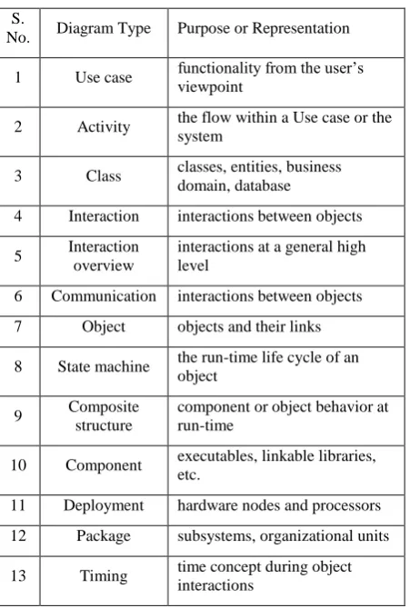
Table 1. UML diagrams & their purposes
S.
No. Diagram Type Purpose or Representation
1 Use case functionality from the user’s viewpoint
2 Activity the flow within a Use case or the system
3 Class classes, entities, business domain, database
4 Interaction interactions between objects
5 Interaction overview
interactions at a general high level
6 Communication interactions between objects
7 Object objects and their links
8 State machine the run-time life cycle of an object
9 Composite structure
component or object behavior at run-time
10 Component executables, linkable libraries, etc.
11 Deployment hardware nodes and processors
12 Package subsystems, organizational units
13 Timing time concept during object interactions
Use case diagrams—deliver the complete view and scope of functionality. The use cases in these diagrams have the behavioral (or functional) explanation of the system. Activity diagrams—offer a pictographic depiction of the flow anywhere in MOPS. In MOPS, these diagrams work more or less similar to flowcharts, illustrating the flow inside the use cases or even displaying the dependencies midst many use cases. Class diagrams—deliver the structure of the domain model. In the problem space, these diagrams signify business domain entities (such as Account and Customer in a banking domain), not the particulars of their implementation in a programming language. Sequence and state machine diagrams—seldom and intermittently used to help us comprehend the dynamics and behavior of the problem better. Interaction overview diagrams—recently added in UML version 2.0; these diagrams offer a summary of the flow and/or dependencies between other UML diagrams. Package diagrams—can be used in the problem space to establish and scope the requirements. Domain experts, who have a justly worthy understanding not only of the existing problem but also of the overall territory of the domain in which the problem exists, help deliver a good understanding of the likely packages in the system. The words ―syntax,‖ ―semantics‖ and ―aesthetics‖ are chosen to replicate the methods or means of accomplishing the V&V of the models. One motive that these words properly represent our quality assurance effort is that they relate directly to the UML models—particularly those models that are created and stored in CASE tools. As a result, their quality can be importantly improved by applying the syntax, semantics and aesthetic checks to them. We will now study these three classes of checks in further detail.
3.
QUALITY MODELS — SYNTAX
All sort of languages have syntax. So do Java, XML and UML. However, two major characteristics of UML differentiate it from the other languages:
UML is a visual language, which means that it has a significant amount of notation and many diagram specifications.
UML is a modeling language, which means that it is not planed primarily to be compiled and used in generation of source code (as programming languages are)— although the trend toward support for both ―action semantics‖ in UML 2.0 and in MDA, both from the OMG, will probably contain the usage of UML in this framework in the future.
Needless to say, improper syntax affects the quality of visualization and specification, also, while a diagram itself cannot be compiled, improper and wrong syntax at the diagram level drips down to the implementation level, causing faults in generating the software code. CASE tools are supportive to guarantee that syntax errors are kept to a minimum. For example, on a UML class diagram, the rules of the association relationship, creation of default visibilities (e.g., private for attributes) and setting of multiplicities are cases of how CASE tools benefit to decrease syntax errors. In UML-based models, when we apply syntax checks, we ensure that each of the diagrams that make up the model has been created in conformance with the standards and guidelines specified by OMG. We also ensure that the notations used, the diagram extensions annotated and the corresponding explanations on the diagrams all follow the syntax standard of the modeling language. Figure 1.3 shows a simple example of a rectangle representing a dog. This rectangle is the notation for a class in UML. The syntax check on this diagram ensures that it is indeed a rectangle that is meant to represent animals (or other such things) in this modeling mechanism. The rectangle is checked for accuracy, and we ensure that it is not an ellipse or for an arrowhead (both of which would be syntactically incorrect when using UML’s notation) that is intended to represent the animal in question. In terms of UML models, a syntax check is a list of everything that needs to be accomplished to achieve the syntax for the diagrams and associated artifacts of UML as laid out by OMG. Permissible deviations on these diagrams in fulfilling with the meta-model can become a project-specific part of the syntax checks. Syntactic accuracy greatly enhances the readability of diagrams, especially when these diagrams have to be read by different sets in different establishments in different countries.
4.
QUALITY MODELS — SEMANTICS
need to identify alternative evaluation techniques. In this context, the traditional and well-known quality techniques of walkthroughs and inspections are tremendously valuable and are castoff more frequently and more thoroughly than for syntax checking. Another example of such techniques, for instance as applied to use case models in UML, is that we claim each of the actors and use cases and act through an entire diagram as if we were the objects themselves. We can insist that testers walk through the use cases, verify the purpose of every actor and all use cases, and determine whether they depict what the business really wants. This is the semantic feature of verifying the quality of a UML model, supplemented, of course, by the actual (non-UML) use case descriptions themselves.
5.
QUALITY MODELS — AESTHETICS
Once the syntax and the semantics are right, we need to reflect the aesthetics of the model (e.g., Ambler, 2003). Very simply, aesthetics implies style. Often, while reading a piece of code, one is able to point out the style or programming and hence trace it to a specific programmer or a programming team. Although the code (or, for that matter, any other deliverable) may be accurate (syntactically) and meaningful (semantically), difference still arises due to its style. The style of modeling has a bearing on the models’ readability, comprehensibility and so on. One example of a factor that affects style is granularity. In good OO designs, the level of granularity needs to be considered, as it strongly affects understandability. For example, how many rectangles (classes) are there on a diagram (as against the previous two checks: ―Is that a class notation?‖ and ―What is the meaning behind this class?‖)? It is, of course, possible that a system with 10 class diagrams, each with 10 classes and numerous relationships, may accurately represent a business domain model—although such large numbers should be regarded as a warning (e.g., Henderson-Sellers, 1996). In another example, one class diagram may have 20 classes (not wrong from a UML viewpoint, but ugly) and another class diagram may have only 1, albeit an important and large one. This aesthetic size consideration is studied in terms of the granularity of the UML models. It requires a good metrics program within the organization to enable it to enhance the aesthetics of the model. Such a model will then offer and provide a high level of customer satisfaction, primarily to the members of the design team but also in their considerations with the business end-user(s).
6.
QUALITY TECHNIQUES AND V&V
CHECKS
The three aspects of quality checks—syntax, semantics and aesthetics—should not be treated as totally independent of each other. A change in syntax may change the meaning or semantics of a sentence or diagram. While syntax is checked minutely for each artifact, an error in syntax may not be limited to the error in the language of expression. This also happens in UML, where syntax and semantics may depend on each other. For example, the direction of an arrow showing the relationship between two classes will certainly affect the way that class diagram is interpreted by the end user. Similarly, aesthetics or symmetry of diagrams facilitates easier understanding (e.g., Hay, 1996), making the semantics clearer and the diagrams more comprehensible to their readers. This brings us to the need to consider the various traditional quality techniques of walkthroughs, inspections, reviews and audits in the context of the V&V checks of syntax, semantics and aesthetics, as shown in Figure 1.4.
Walkthroughs—may be done individually, and help weed out syntax errors (more than semantic errors). Inspections—are more rigorous than walkthroughs, are
usually carried out by another person or party, and can identify both syntax and semantic errors.
Reviews—increase in formality and focus on working in a group to identify errors. The syntax checks are less important during reviews, but the semantics and aesthetics start becoming important.
Audits—formal and possibly external to the project and even the organization. As a result, audits are not very helpful at the syntax level, but they are extremely valuable in carrying out aesthetic checks of the entire model.
7.
SYNTAX CHECKS & UML
ELEMENTS (FOCUS ON ACCURACY)
When we say that we want to apply syntax checks to a use case diagram, what exactly do we mean? Are we checking the use case itself and its specification, or are we checking whether the ―extends‖ relationship arrow in a use case diagram is pointing correctly to the use case being extended? This question leads us to expand our V&V effort to levels beyond just one diagram. In syntax checks, we are looking at the ground-level view of the models. This includes the artifacts and elements of UML, as well as their specifications and documentation. Furthermore, when we check the syntax of these elements, we focus primarily on the accuracy of representation as mandated by UML. Therefore, during syntax checks the semantics, or the meaning behind the notations and diagrams, are not the focus of checking. For example, consider a class diagram that contains Car as a class. The syntax check of the accuracy of this artifact would be something like this:
Is the Car class represented acceptably and correct by attributes (state) and operations (behavior)?
Do the attributes (information associated) have correct types and do the operations (methods associated) have correct signatures?
Is the Car class properly divided into three compartments?
Is the Car class has correctness to be compiled? (This syntax check belongs to implementation.)
In UML terms, when we start applying syntax checks to a use case diagram, we first apply them to the artifacts or elements that make up the diagram, such as the actors and the use cases. In a class diagram, these basic syntax checks apply to a class first and whatever is represented within the class. Since these artifacts are the basic building blocks from which the diagrams and models are created in UML, checking them in terms of accuracy of the UML syntax is the first thing that should be done in any quality control effort.
8.
SEMANTIC CHECKS AND UML
DIAGRAMS (FOCUS ON WHOLENESS
OR FULLNESS AND CONSISTENCY)
Semantic checks deal with the meaning behind an element or a diagram. Therefore, this check focuses not on the accuracy of representation but on the wholeness or fullness of the meaning behind the notation. In the example of the Car class considered above, the semantic check for the model of Car would be: ―Does the Car class as named in this model actually represent a car or does it represent a garbage bin?‖ It is worth noting here that should a collection of garbage bins be named as a Car class, so long as it has a name, an attribute and operation clearly defined, the UML syntax checks for the Car class will be successful. It is only at the semantic level that we can figure out that something is wrong because in real life the name Car does not represent a collection of garbage bins. Because the meaning of one element of UML depends on many other elements and on the context in which it is used, therefore, semantic checks are best performed from a standing-level view of the UML models. This means that we move away from the ground-level check of the accuracy of representation and focus on the purpose of representation. Needless to say, when we stand up from the ground (where we inspect the syntax), a lot more becomes visible. Therefore, it is not just one element on the diagram but rather the entire diagram that becomes visible and important. Semantic checks, therefore, become more intense at the diagram level rather than just at an element level. Taking the Car example further, semantic checks also deal with consistency between diagrams, which includes, for example, dependencies between doors and engine and between wheel and steering. In UML terms, while a class door may have been correctly represented (syntactically correct) and may mean a door (semantically correct). Further, the dependencies between door and car, or between door and driver (or even between door and burglar), will need a detailed diagram-level semantic check. This check will also include many inter-diagram dependency checks that extend the semantic check to more than one diagram. Semantic checks also focus on whether this class is given a unique and coherent set of attributes and responsibilities to handle or whether it is made to handle more responsibilities than just Car. For example, do the Driver-related operations also appear in Car? This would be semantically incorrect. Thus, semantic checks apply to each of the UML diagrams intensely, as well as to the entire model.
9.
AESTHETIC CHECKS AND UML
MODELS (FOCUS ON SYMMETRY AND
CONSISTENCY)
As noted in the preceding sections, the precision and fullness of UML elements and the corresponding individual diagrams are ensured by applying detailed syntax and semantic checks to them. The aesthetic checks of these diagrams and models add a different dimension to the quality assurance activities, as they deal not with accuracy or wholeness or fullness but rather with the overall consistency and symmetry of the UML diagrams and models. They are best done with a birds-eye view of the model. Because these checks occur at a very high level, far more is visible—not just one diagram, but many diagrams, their interrelationships, and their look and feel. This requires these aesthetic checks to be conducted at certain ―checkpoints,‖ where a certain amount of modeling is complete. Therefore, aesthetic checks also require some knowledge and understanding of the process being followed in the creation of the models and the software. The process ensures that the aesthetic checks are applied to the entire
model rather than to one element or diagram. In UML terms, the aesthetic checks of the Car class involve checking the dependency of Car on other classes and their relationships with persistent and graphical user interface (GUI) class cross-functional dependencies. This requires cross-checks between various UML diagrams that contain the Car class as well as checks of their consistency. Furthermore, aesthetic checks, occurring at a birds-eye level, focus on whether the Car class has too many or too few attributes and responsibilities. For example, if the Car class has too many operations, including that of ―driving itself,‖ the entire model would become ugly. Thus, a good understanding of the aesthetic checks results in diagrams and models that do not look ugly, irrespective of their accuracy. Finally, aesthetic checks look at the entire model (MOPS, MOSS, MOBS or any other) to determine whether or not it is symmetric and in balance. If a class diagram in a model has too many classes, aesthetic checks will ensure redistribution of classes. Thus we see that, together, the syntax, semantic and aesthetic checks ensure that the artifacts we produce in UML, the diagrams that represent what should be happening in the system, and the models that contain diagrams and their detailed corresponding documentation are all correct, complete and consistent.
10.
STRENGTHS & WEAKNESSES OF
UML DIAGRAMS
Characteristics of the UML diagrams are divided into two groups: intrinsic and extrinsic. UML diagrams have some basic or intrinsic characteristics that they exhibit irrespective of the type or size of the project in which they are used. These intrinsic characteristics of the diagrams are both their strengths and their weaknesses. UML diagrams also have extrinsic characteristics, which become important when these diagrams are applied in creating practical models. These extrinsic characteristics are dependent not only on the modeling spaces in which the diagrams are used, but also on the type of project in which they are applied. It is therefore possible that a diagram that provides a lot of value to one modeler and is extremely important in one modeling space may not be of much relevance to a different modeler in a different modeling space. The relevance can shift even with different project types and project sizes. For example, a use case diagram in a data warehousing project will not provide the same advantages of quality and relevance as in, say, a new development project. Thus, the extrinsic characteristics of the UML diagrams are derived from the particular objectives of the project in which the diagrams are used.
The study of the intrinsic and extrinsic characteristics of UML diagrams has been dubbed SWOT analysis . Following is a description of what is included in SWOT analysis.
Strengths—intrinsic strengths of the diagram represented by the reason for having that diagram in UML. The strength of the diagram remains the same irrespective of the modeling space, roles of people, and type and size of the project.
Weaknesses—intrinsic weaknesses of the diagram that are due primarily to the lack of modeling capabilities of that diagram, irrespective of the modeling space, roles of people, and type and size of the project. Further in the coming sections we will investigate the strengths and weaknesses of few UML diagrams viz. Use Case Diagram, Class Diagram and Activity Diagrams
11.
USE CASE DIAGRAMS
UML as an "actor") and a system, to achieve a goal. The actor can be a human or an external system. Use Case actually captures the functional requirements of the system. Now we discuss the strengths and weaknesses of this diagram.
11.1
Strengths of Use Case diagrams
One of the significant strengths of a use case diagram is its ability to model the actor. The actor proves clearly to the user—who is involved in specifying requirements—where he exists in the context of the software system. The actor also plays a crucial role in enabling the business analyst to understand and document the user’s requirements. In addition, the actor helps users to express their requirements in greater detail. Once the users see themselves represented on the use case diagram, they find it easier and more attractive (expressive) to explain what they want from the system and how they plan to use it. This involvement of users at a very early stage of the development life cycle is one of the major contributions of use case diagrams in software projects. By their very nature, use case diagrams facilitate discussions among various parties involved in requirements modeling. The business analysts, users and designers of the system are able to see pictorially the structure of their system. Such visual representation is of immense value to the information architect in creating the system architecture. Use cases and use case diagrams help to organize the requirements. The notation for a use case represents a cohesive set of interactions between the user and the system. By simply referring to a use case, a complex set of interaction can be accessed easily, thereby simplifying the discussions. Use cases document accomplish functional requirements. Thus, for projects using use cases and use case diagrams, no separate functional requirements document is needed, although additional operational and interface requirements or additional details such as mathematical formulas may be placed in a separate document. The three relationships of include, extend and generalize between use cases provide means to extend and reuse requirements. This ability of use case diagrams to enable reuse and extension of requirements is one of their major strengths. Actors can also be generalized in use case diagrams. The ability to show pictorially an abstract actor that deals with the most common users of the system is a major strength of use case diagrams. Use cases facilitate tracing of requirements. By providing well-organized documentation of the requirements, a use case creates a trace for a particular requirement throughout the system. This is very helpful in creating and executing acceptance tests by the user. Use case diagrams also provide an excellent mechanism to document the context of the system. By creating a system boundary, it is possible to clearly visualize what is inside the system as compared with external entities in the system, including the users. Use case diagrams provide high-level workflow across the boundary of the system. This creates an understanding of the major internal and external functionalities of the system. Use case diagrams form the basis for creation and documentation of use cases. Therefore, they also help identify major components, objects and functions of a system.
11.2
Weaknesses of Use case Diagrams
Use cases themselves have no good documentation standard. This leads to misperception and debates on what comprises a worthy use case. Most projects proceed on the basis of a predetermined standard for documenting use cases. However, this lack of standards creates an opportunity for modelers and project managers to develop their own standards, as well as their own interpretation of what needs to be documented. Use cases are not intrinsically object-oriented. Use cases appeared
on the software modeling scene through their original use in object-oriented modeling by Jacobson. However, they are not an ideal mechanism to model design-level constructs in the solution space (where object orientation plays an important role). The meaning behind the association or communication relationship between the actor and the corresponding use case is not clear. If the actor initiating the use case is a human actor, then the convention is to show an arrowhead pointing to the use case. However, if the use case represents a series of interactions between the actor and the system, the arrowhead on the association between the actor and the use case does not make sense. The same confusion can exist in the relationship between a use case and a corresponding actor representing an interface to an external system. Use case-to-use case relationships are also not precise, leading to confusion. For example, generalization between use cases will be imprecise, as there are no well-defined attributes and operations in a use case. The other two relationships, include and extend, may also be confusing, as at times it is possible to visually represent the requirements with either of the two relationships. While use cases themselves document business processes, use case diagrams do not exhibit any sequential flow and do not depict any dependency. Thus use case diagrams are not an ideal mechanism to show the flow between different entities within the system. Use cases and use case diagrams do not have a granularity standard. Therefore, sometimes, use cases are written as vast descriptive documents, preventing the modelers from capitalizing on the reusable and organizational aspects of use case modeling. Alternatively, very brief a description results in a huge number of miniature use cases, making them less comprehensible and adaptable.
12.
CLASS DIAGRAM
A class diagram in UML is a type of static structure diagram that describes the structure of a system by showing the system's classes, their attributes, operations (or methods), and the relationships among the classes. Now we investigate the strengths and weaknesses of class diagram.
12.1
Strengths of Class Diagrams
These entities easily represent the database tables. Therefore, strength of class diagrams is their capability to represent relational database schemas in UML format. Multiplicities on a class diagram are also helpful in relational database modeling. Depending on the multiplicities on an association between two classes, primary and foreign keys can be created and assigned to classes. Class diagrams, through their relationship of inheritance, facilitate reuse. Reuse can improve productivity but, more important, it can improve quality. Therefore, one of the strengths of class diagrams is their ability to enhance quality and productivity through reuse. Stereotyping of class diagrams is also an important mechanism to provide a proper architecture. GUI classes, entity classes and controller classes should be properly classified in order to ascertain which classes fit into which specific type. This is certainly an architectural decision or is inclined by the architect. There are also further types of classes, like data, helper or global classes, which should all be stereotyped properly in order to have progress of understanding and readability— and finally the quality of these class diagrams. This provides a major strength in terms of the ability to ―cast‖ classes into relevant stereotypes to enhance the architecture. These stereotypes can also be used to enhance the requirements. In addition to class stereotyping, stereotyping of operations and attributes is allowed, but this should be completed either later in the software development life cycle, in the course of modeling of the solution space, or not finished at all.
12.2
Weaknesses of Classes and Class
Diagrams
Class diagrams do not have any dynamics. They have no concept of time. Therefore, they are only able to represent how the system is structured and what its relationships are. There is no chance to model an if-then-else state on a class diagram. Thus, class diagrams are awfully weak when it arises to modeling the dynamic-behavioral aspect of the system. The class-to-class relationships of aggregation and composition remain to produce confusion in everyday modeling exercises. This is because aggregation has many deviations or variants that do not have corresponding symbolizations in the current UML. For example, within the aggregation link, the unfilled versus filled diamond on the aggregation link signifies shared versus non-shared aggregation, correspondingly. This difference between the two types of aggregation is still being argued. As suggested in the section on putting together a class diagram in difference in the two types of aggregation in the problem space can be evaded in the exercise.
Multiplicity, as shown on class diagrams, can also sometimes lead to confusion. For example, in an aggregation relationship, the multiplicity shown on the diamond side of the aggregation can create misunderstanding, as the aggregator side of the relationship should, by default, be 1 to satisfy a whole-part relationship.
13.
ACTIVITY DIAGRAM
Activity diagrams are graphical illustrations of workflows of stepwise activities and actions with support for choice, iteration and concurrency. In the Unified Modeling Language, activity diagrams can be used to describe the business and operational step-by-step workflows of components in a system. An activity diagram shows the overall flow of control.
13.1
Strengths of Activity Diagram
Activity diagrams model the flow present inside the system. This is, since they are similar to flowcharts and are behavioral
static in nature. Thus, one of the main strengths of activity diagrams is their capability to demonstrate flows within a use case or among use cases and also in the entire system. Activity diagrams complement use case diagrams by visually showing the internals of a use case. Activity diagrams are able to show multiple flows taking place simultaneously within the system. This is achieved drawing the forks and joins (derived from the sync points) on the activity diagrams. ―An activity diagram is like an old-style flow chart except that it permits concurrent control in addition to sequential control that is a big difference‖. This change or difference (to capture concurrency between an activity diagram and a flowchart) is one of the major strengths of the activity diagram. Another important idea shown on an activity diagram (which is different from a flowchart) is that of partitions. Partitions neatly classify activities within the activity diagram based on dependencies among activities and their cohesiveness. They also offer an opportunity to document not only the flow but also the role that is responsible for that flow. Activity diagrams acts as a bridge between use case and sequence diagrams. This enables the text-based documentation of the use cases to be shown pictorially in activity diagrams. At the same time, activity diagrams also enable a high-level view of what happens at the object level in sequence diagrams. Notes, appropriately appearing on the activity diagrams, enable easier reading and understanding of the diagrams for users with no technical background. Explanations of the activities, their dependencies and the decisions points all provide excellent user-level documentation. Activity diagrams have also been used in training users new to a system.
13.2
Weaknesses of Activity Diagrams
Activity diagrams have no structural features, and they do not offer direct evidence on how the system or the requirements are organized and prioritized. Activity diagrams signify use case behavior pictorially. However, they do not typically give a complete picture of the system. For huge and complex use cases, multiple or many activity diagrams are required. The inability of activity diagram to view the full requirements of the system at a glance is their weakness. Activity diagrams portray process flow. Therefore, they should be used whenever there is a need to show dependencies between activities. If used for organizational resolutions, they will lose the value they complement to the requirements model.
14.
CONCLUSION
15.
REFERENCES
[1] Ambler, S. UML Style Guide. Cambridge: Cambridge University Press, 2003.
[2] Armour, F., and Miller, G. Advanced Use Case Modelling. Boston: Addison-Wesley, 2001.
[3] B. Meyer, eds. Upper Saddle River, NJ: Prentice-Hall, 1995, pp. 229–234.
[4] Beck, K., and Cunningham, W. ―Languages and Applications,‖ Proceedings of Conference on OO Programming Systems. New Orleans, LA: ACM Press, NY, 1989, pp. 1–6.
[5] Booch, G., Rumbaugh, J., and Jacobson, I. The Unified Modelling Language User Guide. Reading, MA: Addison-Wesley, 1999.
[6] Chen J., Lu J., and B. Meyer, eds. Nanjing, China: IEEE Computer Society, 1999, pp. 108–117.
[7] Cockburn, A. Writing Effective Use Cases. Boston, MA: Addison-Wesley, 2001.
[8] Constantine, L., and Lockwood, L. Software for Use: A Practical Guide to the Models and
[9] Van. M., Design: Designing Interactive Systems, Harmelen ed., Addison-Wesley, 2001
[10]Douglass, B.P. Real-Time Design Patterns: Robust Scalable Architecture for Real-Time Systems. Reading, MA: Addison Wesley Professional, 2003.
[11]Fowler, M. Patterns of Enterprise Application Architecture. Reading, MA: Addison-Wesley Professional, 2003.
[12]Glass, R. Facts and Fallacies of Software Engineering. Reading, MA: Addison-Wesley, 2003.
[13]Hay, D.C. Data Model Patterns: Conventions of Thoughts. New York: Dorset House, 1996.
[14]Henderson-Sellers, B. Object Oriented Metrics: Measures of Complexity. Upper Saddle River, NJ: Prentice Hall, 1996.
[15]Henderson-Sellers, B., and Unhelkar, B. OPEN Modelling with the UML. London: Addison-Wesley, 2000.
[16]Hudson, W. ―A User-Cantered UML method,‖ in Object Modelling and User Interface
[17]Jacobson, I., Booch, G., and Rumbaugh, J. The Unified Software Development Process.Boston: Addison-Wesley, 1999.
[18]Jacobson, I., Christerson, M., Jonsson, P., andO¨ vergaard, G. Object Oriented Software Engineering: A Use Case Driven Approach. Reading, MA: Addison-Wesley, 1992.
[19]Lauder, A., and Kent, S. ―Two-Level Modelling,‖ Technology of OO Languages and Systems,
[20]Lindland, O.I., Sindre, G., and Sølvberg, A. ―Understanding Quality in Conceptual Modeling,‖ Volume 11 Issue 2, March 1994, IEEE Computer Society Press Los Alamitos, CA, USA
[21]Mellor, S.J., and Balcer M.J. Executable UML: A Foundation for Model Driven Architecture. Reading, MA: Addison-Wesley, 2002.
[22]Miller, G. ―The Magical Number Sever, Plus or Minus Two: Some Limits on our Capacity for Processing Information,‖ The Psychological Review, 63(2), 1956, pp. 81–97.
[23]OMG, Model Driven Architecture Initative; accessed 2004.
[24]OMG. OMG Unified Modeling Language Specification, Version 1.4, September 2001. OMG
[25]Perry, W. Quality Assurance for Information Systems. MA: QED Information Sciences, 1991.
[26]Rosenberg, D., and Scott, K. Use Case Driven Object Modeling with UML: A Practical Approach. Reading, MA: Addison-Wesley, 1999.
[27]Rumbaugh, J., Jacobson, I., and Booch, G. The Unified Modelling Language Reference Manual. Reading, MA: Addison Wesley Longman, 1999.
[28]Schneider, G., and Winters, J. Applying Use Cases: A Practical Guide, 2nd Edition. Boston: Addison-Wesley, 2001
[29]Unhelkar, B. After the Y2K Fireworks. Boca Raton, FL: CRC Press, 1999.
[30]Unhelkar, B. Process Quality Assurance for UML-Based Projects. Boston: Addison-Wesley, 2003.
[31]Unhelkar, B., and Henderson-Sellers, B. ―Modelling Spaces and the UML,‖ Proceedings of the IRMA (Information Resource Management Association) Conference, New Oreleans, 2004.
[32]Unhelkar, B., and Henderson-Sellers, B. ―ODBMS Considerations in the Granularity of Reuseable OO Design,‖ Proceedings of TOOLS15 Conference, C. Mingins and
[33]Warmer, J., and Kleppe, A. The Object Constraint Language. Precise Modeling with UML. Reading, MA: Addison-Wesley, 1998.