Automatic Railway Gate Control System
Using Microcontroller
K.V.Govardhan Rao1, Ch.Srinivas2
Assistant Professor, Department of EEE., St.Martin’s Engineering College, Dhulapally, Hyderabad, Telangana, India1
Associate Professor, Department of EEE, St.Martin’s Engineering College, Dhulapally, Hyderabad, Telangana, India2
ABSTRACT: In everywhere at level crossing between railroad and highway there are so many railway accidents happening due to the carelessness in manual operations or lack of workers. So, this paper describes the automatic railway gate control system using PIC microcontroller for saving precious human lives and preventing major disasters in railway track. Railway gate may be saved for the road users to prevent accidents in terms of train speed at level crossing. This system uses PIC 16F877A microcontroller with the help of sensors. It can divide into two parts. The first part is concern on the hardware development where all electronic components have included. IR sensors, inductive sensors are the input components while buzzer, light indicator, DC motor and LCD display are the output components. These are controlled by the controller circuit. The microcontroller forms the main unit of the system. It receives input signal from the sensors and sends information to the gate motor driver for opening and closing the gate. Besides, the input signal will active LCD display and alarm and indication light circuit was provided as additional part of this system. The first inductive sensor and IR sensor are fixed at a certain distance from the gate and the second sensors are fixed at the same certain distance after the gate. The gate is closed, when the train crosses the first IR sensor and the gate is opened, when the train crosses the second IR sensor. This system deals about one of the efficient methods to avoid train accidents. The second part is based on software programming to operate the hardware structure. Program for railway gate control system is based on PIC microcontroller with PIC basic Pro language.
KEYWORDS: Automatic Railway Gate, Level Crossing, Sensors, PIC 16F877A, DC motor.
I. INTRODUCTION
Railroad is one of transition mode, which has an important role in moving passengers and freights. However, railroad-related accidents are more dangerous than other transportation accidents. Therefore more efforts are necessary for improving its safety.
II. HARDWARE IMPLEMENTATION
The materials and components that are used in automatic railway gate control system will be discussed in the following. As in normal control design, system can be roughly divided as input, output and processing sections. The main components of system are:
1. Microcontroller: PIC 16F877A microcontroller is used as a main control unit to control the process of the whole system.
2. Railway Sensors: They are placed at two sides of gate. It is used to sense the arrival and departure of the train. 3. Motor Driver: The H-Bridge uses the four transistors motor driver circuit that are used to rotate forward or
reverse direction of DC motor for opening and closing the gate.
4. LCD Display: It displays the railway gate open or close section and warning message for road users. 5. Buzzer and light signal: They are used to warn the road user about the approach of train.
6. Power Supply: It is needed to provide 5V DC to microcontroller and 12V DC for motor.
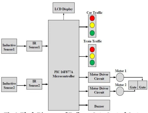
III. OVERVIEW OF THE SYSTEM A. Block Diagram Description
Fig.1. Block Diagram of Railway Gate Control System
Fig. 1 shows over all block diagrams for railway gate control system by using microcontroller (PIC 16F877A). So, one PIC 16F877A microcontroller is used to operate the following function of the railway gate control system: 1. To sense the arrival and departure of the train
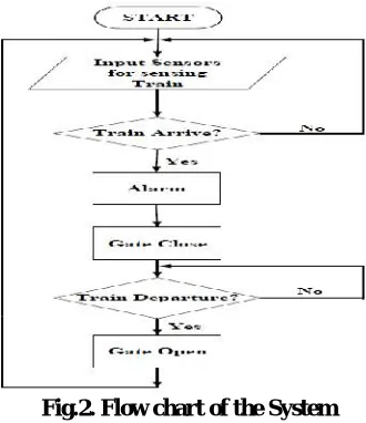
B. Flow Chart
Fig.2. Flow chart of the System C. Algorithm
The algorithms used in the flow chart in Fig.2 are described in steps. STEP 1: Start.
STEP 2: Set the input sensors for sensing train.
STEP 3: Check for the arrival of the train by the sensors. If the train is sensed go to step 4 and step 5 otherwise step 3.
STEP 4: Make the warning signal for the road users. STEP 5: Close the gate.
STEP 6: Check for the train departure by the sensors. If the train sensed go to next step. Otherwise repeat STEP 6.
STEP 7: Open the gate. STEP 8: Go to STEP 2.
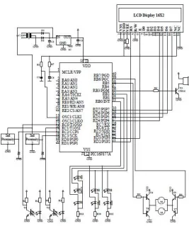
III. CIRCUIT DESCRIPTION
Fig.3 Overall Circuit Diagram of the System
`The main control unit of this system is PIC 16F877A microcontroller and it can manage the control process of all input and output units. Infrared sensor circuit is applied to sense the train on the railway track. The LCD display is used to show the arrival and departure messages of the train. H-Bridge motor driver is to drive the DC motor for gate open and close control. Alarm unit is utilized for warning the road users.
Fig.4 Proposed Model A. Type of Sensors
Photo interrupter ITR9813 sensor is used as an IR sensor in this system. This sensor consists of an infrared emitting diode and an NPN silicon phototransistor in the same package. Phototransistor receives radiation from the IR LED. But when an object is in between, phototransistor could not receive the radiation. Output is taken from the collector pin of the phototransistor.
Fig.5.IR sensor and its circuit diagram
Two inductive sensors are used in this system. This sensor has the following features: Detection of train presence, speed and direction
Switch control
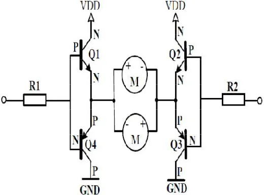
Fig .6.Three wire DC inductive sensor and its circuit diagram B. Working of the H-Bridge Motor Driver Circuit
Fig.7. H-Bridge DC motor Driver Circuit
An H-Bridge allows bidirectional control of a DC motor. To achieve this, it uses four transistors. Each transistors acts as a simple on-off switch as shown in fig.7. This circuit is called an H-Bridge because the transistors are arranged in an H pattern.
No human resource is required. Safety and quality of services Accident avoidance
IV. DISCUSSION
The sensors sense the input and sends to the microcontroller, where if responds and gives command to the particular component with predefined algorithm. The timing condition for the railway gate control system must be set base on the speed and length of the train into the background algorithm which can be easily changed and modified using microcontroller. The DC motor is controlled by the microcontroller for rotations by calculating the code of proper delay in to the microcontroller. This system, a scaled down model attempts to mimic the real time Railway Gate control. This can be realized in real time with the higher horse power motors, controlled by Programmable Logic Controllers and through several Distributed Control Systems (DCS). Employing the automatic railway gate control system at the level crossing may offer several advantages for public. Since, the operation is automatic; error due to manual operation is prevented.
V. CONCLUSION
Automatic gate control system offer an effective way to reduce the occurrence of railway accidents. This system can contribute a lot of benefit either to the road users or to the railway management. Since the design is completely automated it can be used in remote villages where no station master or line man is present. Railway sensors are placed at two sides of gate. It is used to sense the arrival and departure of the train. This system uses the DC motor to open and close the gates automatically when it is rotated clockwise or anticlockwise direction. The LCD display shows the status of the railway gate control system. The system can also generate buzzer and light indicators while the train passing through the level crossing. In this system, this is controlled by using PIC 16F877A microcontroller. Now a day’s automatic system occupies each and every sector of applications as it is reliable and accurate.
REFERENCES
[1] International Journal of Engineering Research & Technology (IJERT) Vol.1 Issue 3, May – 2012 ISSN: 2278-0181 [2] International Journal of Modern Engineering Research (IJMER) Vol.2, Issue.1, Jan-Feb 2012 pp-458-463 [3] http://engineersprojects.blogspot.com
[4] Siti Zaharah, “Transit District Advance Automated Train Detector System Case Study Description”, pp: 115-135. [5] INTELLIGENT RAILWAY LEVEL CROSSING SYSTEM A PROJECT PEPORT
[6] Ahmed Salih Mahdi, Al-Zuhairi, “Automatic Railway Gate and Crossing Control based Sensors & Microcontroller", International Journal of Computer Trends and Technology (IJCTT), Volume 4, Issue 7, July 2013
[7] Krishna, ShashiYadav and Nidhi, “Automatic Railway Gate Control Using Microcontroller”, Oriental Journal Of Computer Science & Technology, Vol.6, No.4, December 2013.
[8] J. Banuchandar, V. Kaliraj, P. Balasubramanian, S. Deepa, N. Thamilarasi,“ Automated Unmanned Railway Level Crossing System”, in International Journal of Modern Engineering Research (IJMER) Volume.2, Issue.1, Jan-Feb 2012 pp-458-463
BIOGRAPHY
K.V.Govardhan Rao is currently working as an assistant professor in St.Martin’s Engineering
CH. SRINIVAS is currently working as an associate professor in St.Martin’s Engineering College,
Dhulapally, Secunderabad Tеlangana. He received B.Tеch degree from Dr.Paul Raj Engineering College, Bhadrachalam, Tеlangana. He obtained his M.Tеch degree from Osmania University College Campus , Tеlangana. His interested areas are Elеctrical Machinеs and Powеr Elеctronics. He has ovеr
08 yеars experiencе in tеaching and he published 07 papers in various international journals.he is the