Automatic Railway Gate Control using 89C51
Prof. P.S. Dhaygude1, Salve Gatha2, Nimbalkar Sneha3, Shinde Vaishnavi4, Bondre Sujata51, 2, 3, 4, 5
Department of Electronics and Telecommunication Engineering .Phaltan Education Society’s College of Engineering, Phaltan
Abstract: Barrier gate is operated manually by a gate keeper. The nearest station shares details about the coming of the railway to the gate keeper. Any type of accidents can be avoided by establishing this system. Sometimes the reaching of the train to the station is late due to some reason ,for specific duration, gate remains closed and this causes a traffic jam around that area. This hazard can be prevented by this system. It uses uses IR (infrared sensor) for detecting the coming as well as going of train .This automatic gate can be controlled using Microcontroller. it uses first sensor to detect the coming of the train and a second one is used to detect the exit of the train. As sensor detects the train then the gate is closed using motor. The gate is closed until the train completely moves away from barrier. When the leaving of train motor operates to open the gate. Hence, automatic of the gate operations at the train barrier is achieved using IR sensors.
Keywords: Automatic Railway Gate Control, 89C51, Level crossing sensor, DC motor.
I. INTRODUCTION
The railway system is the most commonly used transportation mode in India[1]. It has an important role in moving passengers and freights. However, railroad-related accidents are more dangerous than other transportation accidents. Therefore more efforts are necessary for improving its safety.
This system is to manage the control system of railway gate using the microcontroller. The main purpose of this system is about railway gate control system and level crossing between railroad and highway for decreasing railroad-related accident and increasing safety. Railways preferred the cheapest mode of transportation over all the other means. This system is designed using Microcontroller 8051 to avoid railway accidents happening at railway gates where the level crossings.
Microcontroller performs the complete operation i.e., sensing, gate closing and opening. As a train approaches the railway crossing from either side, the sensors placed at a certain distance from the gate detects the approaching train and controls the operation of the gate.
This system was operated after signal received from the sensors. This signal is used to trigger the microcontroller for operating the gate Motor. This system also can be used in parking gate controlling and sliding door system. The abstraction of this system is to provide the advanced control system available to everywhere.
II. OVERVIEWOFTHESYSTEM
A. Block Diagram Description
Fig.1. Block Diagram of Railway Gate Control System
Fig. 1 shows over all block diagrams for railway gate control system by using microcontroller (AT89C51).The 89C51 is low power, high performance CMOS 8-bit microcontroller with 4byte of Flash Programmable & Erasable Read Only Memory (PEPROM)[4]. The device is Compatible with industry standard MCS-51. The on chip flash allows the program memory to be reprogrammed in system or by a conventional non-volatile memory programmer. By combining a versatile 8-bit CPU with flash on a monolithic chip.
B. Flow Chart
NO
YES
NO
YES
[image:2.612.222.409.173.542.2]
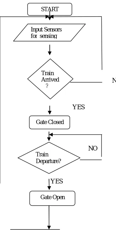
Fig.2.Flowchart for proposed methodology
C. Algorithm
Step 1:.Start.
Step 2: Set the input sensors for sensing train.
Step 3: Check for the arrival of the train by the sensors. If the train sensed go to step 4 and 5 otherwise step 3. Step 4: Make the warning signal for the road users.
Step 5: Close the gate.
Step 6: Check for the train departure by the sensors.
If the train sensed go to next step. Otherwise repeat Step 6. Step 7: Open the gate.
Step 8: Go to step 2.
START
Input Sensors for sensing
Train Arrived ?
Gate Closed
Train Departure?
III.HARDWAREIMPLEMENTATION
The components that are used in automatic railway gate control will be discussed in the following. The control design, system can be roughly divided as input, output and processing sections. The main components of system are:
Microcontroller- AT89C51 microcontroller is used as a main control unit to control the process of the whole system[4]. Railway Sensors They are placed at two sides of gate. It is used to sense the arrival and departure of the train.
Motor Driver -The H-Bridge uses the four transistors motor driver circuit that are used to rotate forward or reverse direction of DC motor for opening and closing the gate.
Power Supply- It is needed to provide 5V DC to microcontroller and 12V DC for motor.
A. Pin Diagram of AT89c51
Fig.3 .Pin Diagram of AT89C51[4]
1) Type of Sensors- A Sensor is used to sense the arrival and departure of the train. An IR sensor generally comprise of two components: an IR Transmitter and IR Receiver. An IR Transmitter is a device that emits IR rays. Similarly, an IR Receiver is a device that detects the IR rays.
Fig.4.IR Sensor Circuit
B. L293D Motor Driver
C. DC Motor
DC motor is the very important part of this system. It accepts the energy in electrical form DC sources and it converted into mechanical energy. When a current carrying conductor is placed in a magnetic field, it experiences a force. DC motors have two directions rotation either forward or reverse. As long as the motor is used in the area of high efficiency (as represented by the shaded area) long life and smooth operation can be expected. However, using the motor beyond this range will result in high temperature rises and deterioration of motor parts. If voltage in continuous applied to a motor in a locked motor condition, the motor will heat up and fail in a relatively short time. Therefore it is important that there is some form of protection against high temperature rises. A motors basic rating point is slightly lower than its maximum efficiency point. Load torque can be determined by measuring the current drawn when the motor is attached to a machine whose actual load value is known.
D. Power Supply
Fig.5. Power Supply design for 5V
Microcontroller operates on +5 volt power supply. The required power supply is derived from 9V transformer. The transformer is connected to rectifier circuit, after converting AC to DC by using rectifier is 9V dc is regulated to +5V by using voltage regulator 7805. So, +5V supply is applied to microcontroller.
IV.CIRCUITDIAGRAM
Fig.7. Circuit Diagram for proposed methodology
V. PROPOSEDMODEL
Fig.8.At arrival of the train, gate is closed
VI.ADVANTAGES
A. In Prevention of accidents inside the gate
B. For Reliable machine which operates without gatekeeper.
VII. APPLICATIONS
A. It can be also used in banks and also in car parking.
B. This is used in security areas like military and also in own apartments
C. It can also be used in schools, colleges etc.
VIII. CONCLUSION
This automatic system helps to minimise the hazard. This system has many advantages for the railway management. This system able to used in villages where gate keeper is not present. The IR sensors are placed on both the two sides of the road. For the functioning of the gate DC motor is used.
REFERENCES
[1] “Karthik Krishnamurthi” , Monica Bobby, Vidya V, Edwin Baby: - International Journal of Advanced Research in Computer Engineering & Technology (IJARCET) Volume 4 Issue 2, February 2015.
[2] Vignesh Shankar:-IJIRST –“International Journal” ,for Innovative Research in Science & Technology Volume 3 Issue 06 November 2016 ISSN (online): 2349-601.
[3] Acy M. Kottalil, Abhijith S, Ajmal M M, Abhilash L J, Ajinath Babu:-International Journal of Advanced Research in Electrical, Electronics and Instrumentation Engineering Volume 3, Issue 2, February 2014.
[4] Book:- Muhammad Ali Mazadi, Jamice Gilliscie Mazadi, Rolil D Mckinlay:- The 8051 Microcontroller and Embedded System using Assembly & C. [5] Atul Kumar Dewangan, Meenu Gupta, and Pratibha Patel, “Automation of Railway Gate Control Using Microcontroller, International Journal of Engineering