ABSTRACT
RAJYAGURU, SAMEER RAJENDRA. Image Processing Substrate to assist Cognitive
Models interact with Dynamic Environments. (Under the direction of Dr. Robert St.
Amant).
Cognitive models have typically dealt with artificial environments or real environments
that are simple. This is because the cognitive models either use indirect approaches to
interact with environments, or in cases where they adopt direct approaches to interact,
the image processing substrate is incapable of dealing with complex interfaces.
However, it is imperative for cognitive models to interact directly with complex
environments in order to ascertain the reliability of the underlying cognition theory. The
image processing substrate proposed in this thesis overcomes the above-mentioned
limitations and enables cognitive models to interact directly with complex environments.
This is due to the functionality provided by the substrate that facilitates representation
and identification of complex visual patterns. As part of the research work for this thesis,
the substrate has been customized to process two interfaces and a cognitive model has
also been built on the ACT-R cognitive architecture that uses the proposed substrate to
IMAGE PROCESSING SUBSTRATE TO ASSIST COGNITIVE MODELS INTERACT WITH DYNAMIC ENVIRONMENTS
by
SAMEER RAJENDRA RAJYAGURU
A thesis submitted to the Graduate Faculty of North Carolina State University
in the partial fulfillment of the requirements for the degree of
Masters of Science
COMPUTER SCIENCE Raleigh, NC August 18, 2003
APPROVED BY:
________________________ _______________________
Dr. Michael Young Dr. James Lester
Biography
Sameer Rajyaguru was born on April 6, 1980. He graduated with a Bachelor of
Engineering degree in Information Technology from Nirma Institute of
Technology, Gujarat University, India in June, 2001. He worked as an intern with
Tata Consultancy Services, Mumbai, India, for 4 months starting from January
2001 to April 2001. He joined the Masters program (M.S.) in Computer Science
Acknowledgements
First of all, I thank my advisor, Dr. Robert St. Amant for his constant guidance
and advice, without which this thesis would not have been possible. I also wish to
thank Kunal Shah, who was my colleague on the project, for his valuable inputs
and efforts that enabled this system to reach this stage of development. I would
also wish to thank Reshma Mehta, Vivek Rao and Nihar Namjoshi, who were
always present to help me out whenever faced with a problem. Finally, I wish to
thank my committee members, Dr. James Lester and Dr. Michael Young for their
Table of Contents
List of Figures ...vi
1. Introduction...1
2. Cognitive Models...8
2.1. A cognitivemodel’s sensory and motor capabilities ...10
2.2. How cognitive models interact with the environment...13
3. SegMan...17
3.1. Pixel-groups representation of SegMan ...19
4. Vision...24
4.1. Vision Processes...25
4.1.1. Low level vision ...25
4.1.2. Intermediate level vision ...26
4.1.3. High level vision...27
4.2. Representational framework for vision ...31
5. Design of the Vision System ...34
5.2. Application-specific Sub-layer ...51
6. Applications...52
6.1. 3d Driver Game...53
6.2. Cell phone interface ...58
7. Conclusion...65
List of Figures
Figure 1: Overview of ACT-R/PM architecture...11
Figure 2: Relationship between ACT-R, environment and iconic memory...12
Figure 3: Segman Architecture ...17
Figure 4: Encoding of neighboring pixels ...19
Figure 5: Pixel-groups in SegMan...19
Figure 6: SegMan's representation of a standard Windows button...21
Figure 7: High-level Architectural Diagram of the integrated system ...37
Figure 8. Original Image ...40
Figure 9. Quantized Image ...40
Figure 10: Laplacian edge-detection kernel ...40
Figure 11. Original Image ...42
Figure 12. Edge Detected Image ...42
Figure 13: Mask for blurring ...43
Figure 14: Pixel connectivity ...46
Figure 16: Cell phone interface...58
1. Introduction
For years cognitive scientists have studied human problem solving in order to
develop theories of cognition that explain intelligent behavior. One successful
approach, as exemplified by the Soar and ACT-R cognitive modeling research
communities, involves building cognitive models based on a common
computational architecture that embodies a unified theory of cognition. Because
these cognitive models are computer programs, they can be evaluated both
qualitatively and quantitatively, often with comparison to human behavior in
psychological experiments.
How cognitive models can and should interact with external environments is an
important methodological issue for the evaluation of cognitive models. As in
many other research fields, especially those that involve simulation of complex
phenomena, designing environments for cognitive models is no easy task.
Ideally, a cognitive model would run and be evaluated in the same environment
that humans live in, so that the results of cognitive modeling experiments could
be directly compared with results of psychological experiments. This is often
impractical, however. Some of the issues that must be addressed include the
realism of the environment (which should match relevant properties of the
environment in which humans exist as closely as possible), the ease with which
experimental control), and the extensibility of the environment to novel research
areas [18].
A number of different approaches have been devised to address such issues. In
the simplest case, a cognitive modeler might define a specification of an
environment, such as a user interface, with which a cognitive model can interact.
When a cognitive model requires sensory input from the environment, it simply
looks up appropriate values from a table and proceeds. Output is handled
similarly. Other approaches involve building dynamic simulations of
environments, adding considerable flexibility. Yet another approach, specific to
the field of human-computer interaction, involves extending a user interface
management system to cater to the input/output requirements of the model. We
will discuss the advantages and disadvantages of these approaches later in this
thesis. We can summarize the problems with them by observing that it is
laborious and time-consuming to test the models with new environments which
each must be designed and implemented by hand for specific experiments. This
observation motivates the work in this thesis: the goal is to produce a more direct
method for cognitive models to interact with their environments, in particular with
user interfaces to computer applications. The advantages of using a direct
approach to interaction over indirect approaches, in addition to addressing the
• Ecological Validity: Simulations are abstractions of real environments. Due
to this fact, they neglect certain unimportant details about the
environments. This could also remove some of the unpredictability and
other behavioral characteristics of the environments from the simulated
interfaces, thereby casting doubts on the validity of the test results.
However, if the cognitive models could directly interact with the
environment, the conclusions would be more reliable.
• Real-world problem relevance: Dealing with real world interfaces gives
cognitive modelers the flexibility to experiment with generic real-world
problems rather than specific problems that are tailor-made for the
purpose of model calibration, as with simulated or artificially tailored
interfaces, the design and maintenance efforts required make it an
infeasible task.
• External standards for comparison: As various theories get proposed,
there arises a need for comparing these theories. As different models
adopt different methods of interaction with environments, the abstractions
also differ, thereby making it difficult to compare them. If all models
interact directly with environments, without using any indirect approaches,
it would be easier to compare them.
• Development effort: Since indirect approach to interaction requires coming
up with an interface tailor-made as per the requirements of the model, its
be done away with, a lot of development effort would be saved. Also, the
information for processing is already available directly from the
environments, which is proved by the direct interaction capabilities shown
by humans; the problem is that the cognitive models do not possess the
capability to extract that information out of the environment directly.
This thesis is one of the results of a research project aimed at giving cognitive
models access to the kind of interactive, off-the-shelf applications that computer
users rely on in their everyday work (and leisure time.) Past work has enabled
cognitive models to interact with simple, relatively static productivity applications
such as word processors (e.g., Notepad) and unpaced games (e.g.,
Minesweeper). The work described in this thesis targets two properties of more
complex environments: dynamic change and moderate visual complexity.
The contributions of this research1 are as follows:
• Direct interaction between environments and cognitive models: As stated
earlier, it would be advantageous to have a direct interaction between
cognitive models and environments. So far cognitive models have been using
various indirect approaches for interaction with environments. The vision
1 This research was carried out in collaboration with Kunal Shah, who graduated with an M.S. in computer science in the summer of
system proposed here would enable a cognitive model to interact directly
with the environment, thereby improving the credibility of the testing of
cognitive theories and also saving a lot of time and effort.
• Extension of existing SegMan functionality: SegMan is a system that was
built earlier with the same goal of assisting cognitive models with direct
interaction with environments. However, SegMan only dealt with static and
simple interfaces. This research overcomes these limitations of SegMan
by providing functionality to process dynamic and complex interfaces. A
description of the extended functionality provided by the vision system
over the SegMan system is provided in Chapter 3.
• Cognitively plausible system: Cognitive modelers base their theories on
the study of human behavior, and the system proposed here is based on
the theory of biological (human) vision proposed by Marr [9]. This makes
the proposed system more cognitively plausible.
Further chapters in the thesis discuss the vision system and related theories. The
thesis comprises seven chapters including the Introduction. A summary of the
contents of each chapter is provided below.
Chapter 2 talks about cognitive modeling. It discusses the architecture of a type
of cognitive models that was considered for this research, viz. symbol-based
indirect approaches to interaction adopted by cognitive models to interact with
the environments. A particular cognitive model, ACT-R, which was used in this
research, is discussed in greater detail, concentrating on the perceptual
substrate architecture for ACT-R.
Chapter 3 discusses the architecture of SegMan, a predecessor of the proposed
system. It describes the feature-based representation adopted by SegMan and
the features supported by it to build and identify patterns. It also discusses the
limitations of the approach adopted by SegMan and how the proposed system
overcomes those limitations.
Chapter 4 introduces the theory of vision as proposed by Marr [9]. It discusses
the levels of vision processes in biological vision, namely high-level,
intermediate-level and low-level, and the type of operations performed at each
level. It also discusses the representational framework for vision as proposed by
Marr [9].
Chapter 5 discusses the design of the vision system. It discusses the two parts of
the vision system, namely the Generic Core and the application-specific part. It
discusses the functionality provided by the Generic Core. The application-specific
part, being individually tailored for applications and environments, is discussed
Chapter 6 discusses the applications considered for this research and the
application-specific parts of the vision system for these applications. The design
of the application-specific parts as well as the interaction between the
application-specific parts and the Generic Core are also discussed. This includes
the functionality provided by the vision system to the cognitive models to
successfully interact with the environments considered.
Chapter 7 concludes the thesis. It summarizes the salient contributions of the
research, the limitations of the vision system, and the future work envisioned for
2. Cognitive Models
Posner defines cognitive science as a "study of intelligence and its computational
processes" [12]. Cognitive models model some aspect of users' understanding,
knowledge, intentions, or processing [3]. Cognitive models embody the theories
put forth by cognitive scientists and test them for correctness.
Most theories of higher-level cognition have until very recently assumed that
lower-level processes would deliver an abstract representation of the
environment, and thus they have not dealt with issues such as visual attention or
intermediate- and low-level perception. Due to this, cognitive modelers have
often assumed a processed representation of the input to fit their theories, which
raises a serious doubt regarding the validity of the results. The research
described in this thesis is specific to a symbol-based reasoning approach to
cognitive modeling.
A symbol system architecture has the capabilities of memory, symbols,
operations and interpretation [12, 11]. Memory is comprised of structures that
persist over time. Above a certain grain-size the structures are independently
modifiable with respect to other structures. Memory structures are used to store
symbol tokens. Symbol tokens are specific patterns that occur in a memory
on memory structures and produce memory structures as output. The output
structure may be a new memory structure or may be a modification to an existing
memory structure. Symbols or memory structures could also specify a list of
operations to be performed. These structures are called variously codes,
programs, procedures, routines or plans. The process of applying these
operations is called interpreting the symbol structure.
Production systems are a type of symbol-based reasoning systems. According to
Newell ([10], as quoted in [1]), “A production system is a scheme for specifying
information processing systems. It consists of a set of productions, each
production consisting of a condition and an action. It has also a collection of data
structures: expressions that encode the information upon which the production
system works - on which the actions operate and on which the conditions can be
determined to be true or false.”
A production system starts with an initial set of data structures. At any time,
based on the current value of the data (knowledge) structures, the conditions for
the productions are tested and the production whose condition is true is selected
to be fired. This production might make some changes to the data structures,
which in turn might lead to other productions being fired. This process goes on
until either there is no production with a true condition or a production with a stop
Notice that, in this account so far, there is no mention of sensory input or motor
output; the focus is on abstract cognitive processing. Over the past few years,
however, this has begun to change. Cognitive modelers have extended their
symbol system architectures to include cognitively plausible mechanisms that
represent and simulate high-level perception and motor activity. The most
prominent work along these lines is on the ACT-R architecture. (In current
cognitive modeling research, four major production systems are generally
recognized: ACT-R, Soar, 3CAPS and EPIC. Our work has mainly focused on
ACT-R, although the techniques we describe in later sections are equally
applicable to Soar and EPIC. For the remainder of this section, we will use
ACT-R as a representative example of a cognitive modeling architecture based on a
production system approach.)
2.1 A cognitive model’s sensory and motor capabilities
ACT-R/PM (ACT-R Perceptual Motor) consists of a set of modules for perception
and action that are integrated with the high-level theories of cognition. ACT-R/PM
architecture is depicted in Figure 1. As shown in Figure 1, ACT-R/PM consists of
a vision module, a motor module, a speech module and an audition module. The
modules of ACT-R/PM generate two types of outputs. The output may be in the
form of chunks being sent to the declarative memory or motor and speech
commands being sent to the environment. We will discuss only the vision and
Vision Module
The functioning of ACT-R/PM's vision module is graphically depicted in Figure 2.
ACT-R internally represents all information in its declarative memory as chunks,
while the iconic memory is a feature-based representation of the information on
the screen. ACT-R can shift its attention to any object in the iconic memory,
which enables it to extract its identifying patterns or features, after which it can
store the object as a chunk in its declarative memory. ACT-R uses three types of
information to guide the shifting of focus across the screen: particular locations or
directions, particular features, and unattended objects.
In addition to encoding visual objects as chunks in the declarative memory, the
vision module also encodes locations of the objects, thereby making it easier for
the higher-level cognition theory to deal with locations. The vision module also
differentiates between the current and past states, thereby facilitating
differentiation between the object of current attention and the objects were
previously attended to. Thus, the main role of vision module is that of extracting
features and converting iconic objects to declarative chunks that can be
processed by the higher-level cognition theory of ACT-R.
Motor Module
ACT-R/PM's motor module is responsible for carrying out the motor commands
issued by ACT-R. ACT-R takes advantage of the parallelism built into ACT-R/PM
by issuing motor commands and carrying ahead with firing of productions while
ACT-R/PM's motor module takes care of carrying out the movement.
The motor module carries out actions in two phases: the preparation phase
followed by the execution phase. At any time only one action can be in the
preparation phase. Subsequent actions are ignored if some command is in the
preparation phase. The preparation phase is responsible for computing the
parameters needed for execution of the movement. This phase is variable in
terms of time taken. If the current movement is similar to the previous one, then
the preparation phase is relatively short. The more the difference between
successive movements, more is the time taken by the preparation phase. The
next phase is the execution phase. As opposed to the preparation phase, which
is dependent on the nature of successive movements, the execution phase
depends on the characteristic of the current movement only.
2.2 How cognitive models interact with the environment
ACT-R/PM interacts with an external environment, usually an interactive
computer application, by tailoring the environment programmatically to the needs
of the model. This is one of many possible approaches. A study of the methods
far been adopting an indirect approach of interaction with the environment. Some
models acquire visual information about the environment by looking up static
properties-based environment specifications. Some others interact with
simulations of environments, whose input and output have been tailored to the
needs of the model. Some others might interact directly with environments, but
expect a feature-based or object-based representation from the user interface
management system.
Explained below are methods of interaction adopted by cognitive models [17].
The methods of interaction were gathered by studying some example cognitive
models, but the study was limited to models that simulated environments as
opposed to those that modeled environments in abstract terms. The most
common methods of interaction that have been adopted by cognitive models are:
APIs
In this method of interaction, the cognitive model interacts with an environment
by calling APIs provided by the environment to query the status of objects. These
APIs provide the model with information about the properties of objects in the
environment. This method of interaction might involve extending the environment
to include such APIs. This is a laborious task but is very convenient for the
model. An example for this type of interaction would be Laird's Soar Quake bots
[5]. The Quake bots interact with the Quake II game by using the interface DLL
Simulated environments
In this method of interaction, the cognitive model is given a specification for the
environment. The model then directly queries this specification for extracting
information about the objects. The objects are encoded in some form in the
specification, in a way that is convenient for the model to understand and tailored
to its needs, and this encoded representation conveys information about the
properties of the objects. Also, the possible actions are encoded along with
information about the preconditions and the effects of the action. The
preconditions of the action define the state of the environment that constrains the
execution of the action. The effects of the action define the state of the
environment after the action has been performed. Due to this reason, however,
the simulated environment has to be built with great care, as the environment
has to respond to the actions as per the effects specified in the specification. Due
to all this complexity involved in coming up with a specification of the
environment and the level of detail involved in generating the specification,
makes it a time-consuming and a laborious task.
Extend user interface management system
In this method of interaction, the cognitive model adopts a more direct approach.
The user interface management system is extended so as to return
feature-based or object-feature-based representations of objects that suit the input/output
requirements of the model. ACT-R's visual interface is an example of this method
All of these methods, despite their flexibility from the point of view of the model
developer, involve a certain level of indirection from the environment. Extensive
effort needs to be expended in order to tailor the environment to suit the model's
needs. It is highly desirable to do away with this level of indirection and have the
cognitive model interact directly with the environment. The advantages of doing
3. SegMan
Segman is a perceptual substrate developed by Riedl and St. Amant [17, 13] that
facilitates direct interaction between cognitive models and static interfaces such
as a standard windowing system. Segman sits above the operating system and
provides hook functions that other programs can use to perceive and manipulate
the graphical user interface. Segman provides this functionality by parsing the
screen and segmenting it into well-understood features and widgets that can be
used by other programs.
The architecture of the system is shown in Figure 3. Currently Segman only
supports the Microsoft Windows interface as it has been configured to process
and recognize widgets specific to the Windows environment.
Segman.dll is a dynamic-link library of code written in C++. It provides
functionality for capturing the Windows screen and breaking it into groups of
like-colored pixels, known as pixel-groups. The pixel-groups are discussed in more
detail later in this chapter.
The SegMan substrate is a collection of Lisp routines that use the functionality
provided by the DLL. They retrieve the pixel-groups from the DLL's memory,
process them and identify and/or classify them by subjecting them to some
predicates. SegMan internally represents the state of the Windows screen as a
list of pixel-groups, and symbolic references for what they might look like and
what they might be used for.
On top of this substrate is a functional substrate, which comprises of programs
and scripts that access the SegMan data structures and functions to solve
As of the date of the creation of this thesis, the controller interface is still under
construction. The intent is to provide functionality to planners and cognitive
models to interact directly with the interfaces.
3.1 Pixel-groups representation of SegMan
SegMan uses simple routines to
process the Windows interface.
The DLL captures the Windows
screen and represents it as a set of
pixel-groups. Pixel-groups are
neighboring pixels of similar
intensity. An example of a
pixel-group-based representation of an
image is shown in Figure 4. Here
the pixels belonging to the letter 'F'
belong to the same group as they are of similar intensity. Similar is the case for
the other pixel-groups shown in the figure.
Once the pixel-groups have been identified,
shapes, and relationships between shapes,
are examined. Then, based on either the
arrangement of pixels within the group, or the
Figure 4: Encoding of neighboring pixels
number pertaining to the neighboring pixels for each pixel in the group,
identification and classification are performed.
Pixel-neighbors
In SegMan, the relationship between neighboring pixels is encoded using
numbers. The encoding scheme used is shown in Figure 5. The connectivity
used here, the eight-connectivity, was described earlier. In this scheme, there is
a number associated with each of the possible eight positions where a
neighboring pixel can lie, relative to the pixel under consideration. Each of these
numbers corresponds to a unique bit in a binary number. Thus, 0 (west)
corresponds to the right-most bit, or the number 1. The pixel-neighbor value for a
pixel is the number that results after a binary '&' operation is performed over the
encoded representations for all of the pixel's neighbors.
Pixel Patterns
One of the functionality provided by SegMan is that of defining pixel-patterns. A
user can define pixel-patterns for pixel-groups by specifying a combination of
some of the pixel-group-level features supported by SegMan. The features are in
addition to the pixel-neighbor value feature and are mentioned below:
• Count: This indicates the number of pixels in the group.
• Size: This is the area of the group's bounding box.
• Area: This indicates the ratio of count to size
• Width: Width is the width of the group's bounding box.
• Red: Red is a component of the group's RGB value.
• Green: Green is a component of the group's RGB value.
• Blue: Blue is a component of the group's RGB value.
• Color: Color is the group's numerical RGB value.
• Proportion: Proportion is the group's height / width, and 0 if width is 0.
Combinations of these features, along with the pixel-neighbor value feature, can
be used to define pixel-patterns. An example of the way feature identification is
performed in SegMan is the process of identification of a button in the Windows
interface.
A standard Windows button is a rectilinear
feature that appears to be raised out of the
screen. SegMan segments a button into three
parts as shown in Figure 6. One part is the
light-colored 'L' shape formed on the top-left
of the button, the other part is the body of the button and the third part is the
dark-colored 'L' shape formed on the bottom-right of the button. In order to
identify a button, SegMan checks for a rectangle with a lighter-colored 'L' shaped
pixel-group on its top-left corner and a darker-colored 'L' shaped pixel-group on
its bottom-right corner.
Figure 6: SegMan's representation
3.2 Limitations of SegMan
By generating a declarative representation of a visual display, SegMan provides
a way for cognitive models to interact directly with an environment. However,
SegMan's simplistic approach to image processing gives rise to certain
limitations. This research proposes to overcome these limitations. The limitations
of the SegMan system, and the ways in which they have been overcome in the
vision system, are listed below:
• Pattern complexity: As mentioned above, SegMan builds patterns using
pixel-neighbor values and some other simple features. This enables
SegMan to process simple interfaces, like the Windows interface,
effectively. However, it is not always possible and efficient to use
pixel-level heuristics to build patterns. This approach of SegMan makes it
harder to build and represent more complex patterns such as the cell
phone interface described in Chapter 6. The proposed system, instead of
considering pixels as the atomic structure to build patterns, considers
segments (pixel-groups) as the atomic structures for pattern building. This
allows for more complex patterns to be represented and processed.
• Compatibility with biological vision: Since the goal of the research is to
assist the cognitive models to interact directly with environments, it is
imperative that the proposed approach be cognitively plausible. SegMan's
architecture was not built on the basis of some well-studied cognitive
based on the theory of biological (human) vision proposed by Marr [9].
This makes the proposed system cognitively more plausible.
• Scalability: SegMan uses pixel-level relationships to build patterns, which
makes it difficult to process newer interfaces. Currently, SegMan
successfully processes the Windows interface. However, it is difficult to
extend the functionality to process other interfaces. The proposed system
allows for patterns to be built by specifying relationships between
segments. The segments themselves can possess identifying
characteristics. This enables the user to conveniently specify complex
patterns in a way that is generic. Also if the identifying characteristics are
chosen wisely, the identification is easy to scale to different interfaces for
4. Vision
Vision is a very complex process. Through it we derive a rich understanding of
what is in the world, where objects are located, and how they are changing with
time. Vision is thus an information-processing task. Vision could be mistaken for
being simple, due to the ease with which it comes to humans. However, upon
conscious reflection, one realizes that vision is, in fact, a very complex task.
There are two aspects to understanding vision: the processes that enable the
extraction of information from images and the representation of the information
extracted from images. Marr [9] states, "The study of vision must therefore
include not only the study of how to extract from images the various aspects of
the world that are useful to us, but also an inquiry into the nature of the internal
representations by which we capture this information and thus make it available
as a basis for decisions about our thoughts and actions."
There has been an interest in comparing computer vision and human vision.
However, they differ fundamentally at the level of hardware. Human vision
comprises neurons and computers possess circuits, and they are fundamentally
different [8]. Marr [9] suggests that there are three different levels at which
problems in vision, rather any information-processing task, can be described,
namely computational theory, algorithm, and mechanism. Computational theory
properties of this mapping and its appropriateness and adequacy for the task at
hand. The algorithm level deals with the details of the representation of the input
and output and the method used to transform one representation to the other.
The mechanism level deals with the realization of the algorithm and the
representation physically. Thus, considering vision as an information-processing
task, an attempt can be made to describe the processes in the two vision
systems at higher levels, i.e. computational theory and algorithm level, even
though both are different at the hardware or the mechanism level.
4.1 Vision Processes
The retinal image provided by photoreceptors can be thought of as a large array
of continuously changing numbers that represent light intensities. From this array
of light measurements the visual system does not achieve an understanding of
what is in the scene in a single step. The process of vision can be viewed as the
construction of a series of representations of visual information with explicit
computations (processes) that transform one representation into the next. Ullman
[19] categorizes the processes involved in visual perception into three levels:
low-level vision, intermediate-level vision and high-level vision.
4.1.1 Low level vision
Low-level vision is associated with the extraction of certain physical properties
from the image, such as object boundaries, depth or 3D shape information. A
They are spatially uniform and parallel, i.e. similar processing is performed
simultaneously across the visual field. Also they are bottom-up in nature, i.e. the
operations are performed in the same way regardless of the task at hand and
without the knowledge of specific objects or context. In other words, low-level
vision is simply data-driven. Another characteristic of low-level vision processes
is that they can be validated to be correct and accurate. Low-level vision includes
processes like edge-detection, stereo vision, and visual motion.
4.1.2 Intermediate level vision
The term intermediate-level vision does not imply a strict sequence or order of
operations. In fact, intermediate-level vision is not required for every problem and
might be skipped altogether. Nevertheless some intermediate processing
appears to occur for some kinds of tasks.
Consider an example in which it is to be decided whether an object can move
from its current position to a target position without colliding with other objects in
its vicinity. Problems like this do not require recognition of individual objects, nor
can such problems be solved by primitive low-level operations. This problem
belongs to intermediate-level vision. Intermediate-level vision is concerned with
extracting shape properties and spatial relations among objects from the image.
Spatial relationships play a very important role in visual classification and
recognition. The visual analysis of shape and spatial relations also plays an
associated with intermediate-level vision are non-uniformity, open-endedness,
and task-dependence. Non-uniformity means that the same operations cannot be
performed across the entire visual field to bring out all spatial relationships and
shape level information. Also there is no clear bound on the number of shape
properties or spatial relationships that can exist, thereby making
intermediate-level vision open-ended. The spatial relationships and shape properties are also
dependent on the task at hand, thereby making the intermediate-level vision
processes task-dependent.
Some operations that comprise intermediate-level vision are shifting and
indexing, region-coloring and boundary tracing. Shifting is the general operation
of moving the focus of processing to a required location, while indexing is the
shifting of processing focus to a salient location in the visual field. An example of
shifting would be the shifting of focus that occurs when given the problem of
searching a green X that is surrounded by green Ts and brown Xs. An example
of indexing would be searching a blue X that is surrounded by brown Ts and
green Xs. Region-coloring is equivalent to the process of image segmentation
described later. Boundary tracing is the tracing of contours sequentially in a given
direction.
4.1.3 High level vision
High-level vision is concerned with visual object recognition. A characteristic of
the world, such as a catalog of objects stored in long-term memory. This makes it
more intimately related to the problems of memory organization, retrieval,
expectations and reasoning. The steps involved in the object recognition process
are discussed below. A more detailed discussion of these steps can be found in
[15].
• Preprocessing: This step involves processing the image and getting it
ready for further processing. Some typical operations carried out in this
step include noise removal, edge detection and quantization.
• Data Reduction: Data reduction aims at reducing the amount of data to be
processed. An example for this could be image segmentation. It might
also facilitate the next step by making it easier to extract feature-based
information from the image.
• Feature Analysis: During feature analysis, identifying features are
extracted from the image and used for object identification or
classification. Pattern classification could be an example of the operations
performed in this step.
There are various possible approaches to object recognition. They are discussed
below.
One approach of object recognition is the direct method. In this method, all
possible views of the object are stored and correlation is used to compare and
required. Also scalability is a problem, as adding an object would mean capturing
and adding all the views for the object to the knowledge-base of the system.
Apart from this approach, there are some shape-based approaches to object
recognition. They are described as follows:
1. Invariant properties methods. These methods are based on the assumption
that objects have some invariant properties, such as some transformation or
filter or some operation that is guaranteed to consistently let one identify an
object uniquely and reliably immaterial of the changes the object undergoes.
Thus, in the invariant properties scheme, the object identification process is
broken down to extracting the invariant properties and then based on the
extracted value of these properties, identifying the object. Invariance does not
mean that the property has to hold a constant value for the object to be
identified. It could also be specified as a range of values. Now it is possible
that more than one object may have the same value for one of the invariant
properties, or in the case of range of values, overlapping ranges. In such
cases, more than one property is used to represent the object, giving rise to
feature spaces. These methods, however, have certain limitations. The
invariant properties cannot be assumed to hold for all views of a particular
object. Also, it is infeasible to come up with a set of invariant properties that
can be generically used to create unique identifying signatures for objects.
helpful in the object recognition process. But, these methods cannot
constitute the entire process.
2. Parts decomposition methods. These methods work by first decomposing
objects into simpler parts. These parts are classified into different classes of
"generic" components. Then, some relationships between these simpler parts
are used to identify the objects. The invariant properties approach may be
used to identify and classify the simpler parts that the object has been
decomposed into. Once the parts have been classified, two approaches exist
for object identification. In one approach, the parts are grouped together to
form a higher level component of the object. The other approach uses
invariant properties to identify objects and the invariant properties used here
are relationships between the simple parts. Parts decomposition methods
combine the invariant properties approach with hierarchical representation of
structure to achieve the target of object identification. They are, thus, more
robust than the invariant properties methods. However, these methods face
trouble when dealing with 3D-object spaces. For 3D-object spaces, these
methods face the same difficulty as of the invariant properties methods, viz.
searching for the invariant properties that are valid across views.
3. Alignment methods. The problem with the methods mentioned above was
their inability to adapt to the change that the object's view undergoes due to
transformations in a 3D space. Transformations cause discrepancies between
Alignment methods assume that there is a finite set of "allowable
transformations" that an object can undergo. These methods, then search for
the best fitting stored model as well as the transformation that when applied
to the stored model, would yield the best fit with the viewed object. Since,
complete 3D information is not captured in the viewed object, it would be
better to run the necessary transformations on the stored 3D model of the
object and then compare the result with the viewed object. However, it is also
possible to do it the other way around for some select transformations. These
transformations are the ones that act within the image plane.
4.2 Representational framework for vision
The purpose of vision is to process images and extract useful information out of
them. The representation of the input to the vision system is well understood and
agreed to be an image that is an array of intensity values as detected by the
photoreceptors in the retina. The representation of the output of the vision
system is harder to understand. Marr [9] suggests that it is almost impossible to
deliver a completely invariant shape description from an input image in only one
step. According to him, vision must follow a sequence of representations, starting
with describing information that can be extracted directly from the input images,
but represented in such a way so as to facilitate further information extraction
towards the final goal of extracting shape and object level information. According
to his theory, vision must follow the following sequence of representations to
1. Images. This is the initial representation and consists of an array of intensity
values. This is the most primitive level of representation that comes directly
from the sensors (photoreceptors in case of humans).
2. Primal sketch. This is the representation that is obtained by processing the
image and extracting information about the changes and structures in the
image. Primarily it involves things like detection of intensity changes,
representation and analysis of local geometrical structure and the detection of
illumination effects. This representation conveys information in a
viewer-centered coordinate frame. Some primitives that might be useful to extract the
information required to generate a primal sketch would be edge segments,
boundaries, terminations and discontinuities, and groups.
3. 2-1/2D-sketch. 2-1/2D-sketch is the representation derived from the primal
sketch. To create this representation some additional information like depth
are taken into account. The result is a sketch of the visible surfaces in the
image and their orientation. Also taken into account are discontinuities in
depth that might suggest boundaries of objects lying in different planes. Just
like the primal sketch, even this representation conveys information in a
viewer-centered coordinate frame. Some primitives that might be useful to
extract information required to generate a 2-1/2D-sketch would be local
surface orientation, distance from viewer, and discontinuities in depth.
4. 3D-model representation. All the earlier representations carried information
that this representation depends critically on the vantage point and hence is
unsuitable for recognition tasks. This information needs to be converted to an
object-centered coordinate frame and that is what the 3D-model
representation contains. This representation describes shapes and their
spatial organization in an object-centered coordinate frame, using a modular
hierarchical representation. The shape level primitives of interest here are
5. Design of the Vision System
Based on the background information in the previous two chapter, two of the
goals of the research presented here are to improve the image processing
capabilities provided by SegMan (thereby improving the access of cognitive
models to more complex application environments) and to produce a
computational system for cognitive models that can perform image processing in
a way that more closely corresponds to what is known about human visual
processing. To do this with complete generality is far beyond the scope of this
research, and in fact appears to require solving the general vision problem. In
order to make this problem more tractable, the research has focused on a
particular subset of visual environments.
Two environments were considered and processed as part of this research. One
of them is an interactive gaming environment and the other is a static interface of
reasonable complexity. The interactive gaming environment is that of a car
driving game in which the goal is to avoid collisions and to drive in the correct (for
this game, the right) lane. The static interface is that of a cell phone in which the
goal is to identify the locations of the keys on the keypad. These environments
The design of a vision system is not dependent solely on the model and its
requirements; the characteristics of the environment, such as the example
environments above, also play a decisive role. Designers must consider the
efficacy of candidate image-processing algorithms in processing the environment
along with the requirements of the cognitive model. For this reason, it is
necessary to classify the environments and identify the characteristics of the
environments that need to be considered while making this decision, as a
candidate algorithm that might be well-suited for an environment might be
ill-suited for another. Shah has developed a classification scheme by which
computer applications can be characterized [16], based on collaborative work
within our research group. The classification is by no means comprehensive.
There are many attributes of environments that can be considered while
classifying them, such as the input/output characteristics, level of strategic
planning required, etc. and only the visual aspect of environments has been
considered in order to come up with the classification. Accordingly, environments
can be classified as follows.
• Static versus Dynamic environments. In some environments, changes
take place only in response to the actions of the model. Such
environments belong to the class of static environments. An example of a
static environment would be the interface to an operating system or the
interface to a game of Minesweeper. As opposed to static environments,
Such environments belong to the class of dynamic environments. An
example of a dynamic environment would be a first person shooter game
like Quake. Dynamic gaming environments have a higher level of
unpredictability and hence real-time monitoring of the environment needs
to be supported by the image-processing substrate.
• Predictable versus Unpredictable environments. In some environments, it
is possible to predict the next state of the environment, given the current
state, with a high-level of certainty. These environments are said to be
predictable. An example of a predictable environment would be the
interface to an operating system. As opposed to predictable
environments, in an unpredictable environment, it is tough to predict the
next state of the environment, given the current state. An example would
be a first person shooter game like Quake. Static environments generally
tend to be more predictable than the dynamic ones.
• "Simple" versus "complex" environments. The complexity involved in the
design of algorithms for the image-processing layer also depends on the
level of complexity associated with the environment. There are several
features that could contribute to the complexity of environments: shape,
color and texture, and spatial relationships. Geometrically standard
shapes like rectangles and circles are easy to recognize, however,
recognition of arbitrary shapes is highly complex. Complex textures can
Cognitive Models, Controllers and Planners
Environments Image Processing Substrate
Generic Core Application specific layer
SegMan
Sensor Effector
relationships or unreliable spatial relationships can make
image-processing a highly difficult task.
• Sparse versus Crowded environments. A final factor is the number of
objects to be processed, or the number of objects that need our attention.
A greater number of objects needing our attention simultaneously might
justify a parallel processing design.
As noted earlier in this chapter,
developing a vision system that is
generic appears to require solving
the general vision problem. Due to
this, a part of the vision system is
specifically tailored to the
environment being considered.
The architecture of the vision
system consists of a Generic and
an application-specific layer as
discussed below.
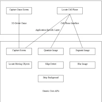
The high-level architectural diagram of the integrated system is shown in Figure
7. As shown in the figure, the vision system (also referred to as the
image-processing substrate) lies between the cognitive models and the environments.
Figure 7: High-level Architectural Diagram of
The cognitive models gain information about the environments by querying the
image-processing substrate. The substrate processes the images captured from
the environments to procure the information required by the cognitive models.
The substrate uses SegMan for sensor and effector functionality. The
image-processing substrate is made up of a Generic Core part and an Application
specific part. The Generic Core consists of functionality that is not specific to a
particular environment or interface and hence applicable to all domains and
interfaces. However, all environments need some application-specific knowledge
regarding the structure of objects, types of objects, complexity of objects, etc.
Due to this reason, the vision system consists of an application specific layer
sitting on top of the Generic Core. The application specific layer makes use of the
functionality offered by the Generic Core in order to carry out its task.
5.1 Generic core
The Generic Core performs functions that fall in the preprocessing stage of the
object recognition process. It works on a captured image that is a snapshot of the
visual environment. The following functionality is incorporated in the Generic
Core:
CaptureScreen
This function allows the model to capture a snapshot of the screen thereby
Quantization
Image quantization is the process of reducing the image data by removing some
of the detail information by mapping groups of data points to a single point [20].
Usually the captured image contains a level of detail (in terms of number of
values in the R, G and B streams in the image) greater than that needed to serve
the model's purpose of controlling the game effectively. So, at times, it is possible
to filter out some information from the captured snapshot, thereby reducing the
amount of processing that needs to be done, and still retain enough information
to allow the cognitive model to carry out its function effectively. This function
quantizes the number of color levels per stream used in the image to a value
appropriate to serve the model's needs. The pseudocode for the procedure is as
follows:
1. Compute the number of discrete quantized levels in each stream based on
the quantization factor specified by the user
2. For each pixel in the image
2.1. Split the intensity value into individual streams
2.2. Compute the quantized value of each stream
2.3. Combine the split streams and update the intensity value of the pixel to
Figure 8. Original Image (From [16]) Figure 9. Quantized Image (From [16])
The quantized value in 1.2.2 is computed by normalizing each intensity value
from a continuous range [0,255] to the nearest value in the discrete range [0, 1],
the individual discrete values of which are determined by the step-size computed
from the quantization factor. A snapshot of the 3D-driver game is shown in Figure
8 and Figure 9 to illustrate the working of this operation.
Edge Detection
At times, the user may be interested
in, not the actual values or
intensities of the pixels, but the
pattern of change of intensities in
the image. Edge detection highlights changes in intensity values in the image. An
edge is a property attached to an individual pixel and is calculated on the basis of
the relationship it shares with the pixels in its neighborhood. Thus, edges serve
as a way of implicitly identifying the segments in an image.
Edge detection is performed by locating the points of intensity-discontinuity in an
image. The vision system uses convolution filters to perform edge detection.
Currently, edge detection is implemented using a 3x3 Laplacian kernel (Figure
10). The reason for choosing Laplacian mask, over some other masks, was the
rotational symmetry of the Laplacian mask. With the Laplacian mask, as can be
seen from the coefficients of the mask, edges from all orientations will be seen.
Also, the sum of coefficients is zero, which means that the overall intensity of the
image will be lost, resulting in only the edges being visible.
There are some other masks, such as the Sobel edge detection masks and
Prewitt edge detection masks that provide, in addition to the information about
the presence or absence of an edge, the direction of the gradient, which is
perpendicular to the edge itself. The direction of the gradient is the direction
along which the gray levels are changing. Also, since they provide information
about the direction of the gradient, in a way they also provide information about
the direction of the edge. A snapshot of the 3D-driver game is shown in Figure 11
With edge detection based methods, however, noise can create problems such
as discontinuous or broken edges. The edge mask can be tuned to make it more
or less sensitive. A couple of parameters that govern the sensitivity of a mask are
Figure 11. Original Image (From [16]) Figure 12. Edge Detected Image (From [16])
the size of the mask and the value of the threshold. A more sensitive mask will
detect even the faintest of edges, but will also be more susceptible to noise. A
more sensitive mask would be a smaller one, and also one with a lower threshold
value (i.e. a 3x3 mask is more sensitive than a 5x5 mask, if both have the same
threshold value). A less sensitive mask, i.e. a larger one or one with a higher
threshold value, will be less prone to noise, but it might miss some very faint
edges in the output.
The Generic Core of the vision system supports convolution operations and also
operation. Although edge detection has been implemented in the vision system
using the Laplacian mask, it is simple to implement a customized version of edge
detection by using the interfaces provided.
Blur
Blurring is another convolution operation also known as smoothing or averaging.
It is used for removing random noise. The filter used in blurring operations is a
low-pass filter. After blurring is performed, each
pixel value is replaced by the weighted-average of
the surrounding pixels. The coefficients for
weighted average are the coefficients of the mask
used for blurring. Blurring reduces the damage due to noise by spreading the
intensity of noise over a larger area, thereby resulting in a smoother image.
However, blurring also filters out the high frequency components of the segment
boundaries in the image. A blurring mask of larger size filters out more of the
higher frequency components than a smaller one. Also the coefficients of the
mask are important for the efficacy of the blurring operation.
The blurring mask used in the blurring operation implemented in the vision
system is shown in Figure 13. There are better blurring kernels such as the
Gaussian filter. As stated above, the convolution operations of blur can be
implemented with the mask of the user's choice very easily.
Strip Background
This functionality, built into the generic core of the vision system, is based on
some assumptions about the environment. It is based on the assumption that
background pixels cover a greater part of the image. Hence, this algorithm looks
for peaks, above a certain threshold, in the histogram of intensity distribution for
the image. These peaks correspond to the background intensity pixels. Using
such threshold technique for removing the background means that it would only
perform well in cases where the foreground objects cover a major part of the
picture. The algorithm for this is as follows:
1. Compute the histogram of pixel intensity distribution for the image
2. For each intensity value that is above the threshold
2.1. For each pixel in the image
2.1.1. If the pixel is a background pixel
2.1.1.1. Mark the pixel as a background pixel
Locate Moving Objects
This functionality, built into the generic core of the vision system, takes two
images as input and returns the portions of the image that indicate movement.
The binary operator "xor" is used for this purpose. Currently, in the vision system,
this is implemented as an "xor" function, but it could be implemented by
overloading the binary operators for the image class. The other binary operations
"and", "or" and "xor" operations. Also the unary not operator could be useful.
There are two ways of using "xor" for locating the areas of motion: on the images
themselves or the edge detected images.
The algorithm for locating dynamic parts of the image, takes two images, which
are the consecutive snapshots of the environment, as inputs and returns an
image that comprises of the parts of the image that indicate motion. The
algorithm for this is as follows (Image1 is the first (earlier) snapshot and Image2
is the second (later) snapshot):
1. For each pixel in the image
1.1. If the intensity at the pixel in both Image1 and Image2 are the same
1.1.1. Record the pixel as belonging to a non-moving part of the image in
Image3
1.2. Else
1.2.1. If the pixel is part of a segment that is classified as a background
segment
1.2.1.1. Record the pixel as belonging to a non-moving part of the
image in Image3
1.2.2. Else
1.2.2.1. Record the pixel as belonging to a moving part of the image
1.2.2.2. Set the intensity of the pixel in Image 3 to the intensity of the
pixel in Image2
2. Return Image3
Segmentation
The goal of image segmentation is
to find regions that represent
objects or meaningful parts of
objects [20]. Image segmentation
methods detect object boundaries
based on either a measure of
homogeneity within the pixels of a region or a measure of contrast between
pixels of a region and those of surrounding objects. The algorithm proposed uses
a measure of homogeneity among pixels to detect object boundaries, specifically
the algorithm looks for similarity in intensity values.
There are three ways of considering low-level connectivity of a pixel:
four-connectivity, six-connectivity and eight-connectivity as shown in Figure 14. The
algorithm proposed uses eight-connectivity for the purposes of computing the
neighbors of a given pixel.
For intensity images (i.e., those represented by point-wise intensity levels) four
popular techniques for segmentation are: threshold-based methods, edge-based
methods, region-based methods, and connectivity-preserving relaxation methods
[2]. Threshold techniques work by dividing the color spectrum into various
"zones" and then identifying a region based on what "zone" the intensity of the
pixel falls into. These techniques are effective when the intensity levels of the
objects fall squarely outside the range of levels in the background. Because
spatial information is ignored, however, blurred region boundaries can create
havoc. Edge-based methods are based on contour detection. However, their
weakness in connecting together broken contour lines makes them, too, prone to
failure in the presence of blurring. Region-based methods proceed by partitioning
an image into connected regions by grouping neighboring pixels of similar
intensity levels. Adjacent regions are then merged under some criterion.
Over-stringent criteria create fragmentation; lenient ones over-merge. The main idea of
a connectivity-preserving relaxation-based segmentation method, usually
referred to as the active contour model, is to start with some initial boundary
shape represented in the form of spline curves, and iteratively modify it by
applying various shrink/expansion operations according to some energy function.
With such methods, getting trapped into a local minimum is a risk.
The algorithm implemented in the Vision system is based on region merging or
growing. based methods can be based on splitting or merging.
Region-splitting algorithms, also known as multi-resolution algorithms, consider a region
to merge it with similar homogenous parts of its neighboring regions. If it does not
pass the homogeneity test, it is split into smaller regions and each such region is
then considered individually for homogeneity. A region-merging algorithm starts
from the lowest level and keeps growing the region by merging it with other
surrounding homogenous regions.
The vision system uses a region-growing algorithm for image segmentation. The
algorithm performs in two phases. In the first phase, it performs the assignment
of segment labels to pixels based on the homogeneity between neighboring
pixels, and in the second phase it performs segment merging for homogenous
segments. Rather than using flood-fill, the system uses a scan-line-based
algorithm, as flood-fill based techniques tend to be slow. The segmentation
algorithm is as follows:
1. For each pixel in the image
1.1. If it is possible to form a 3x3 block of homogenous pixels
1.1.1. Search for an appropriate label to be assigned for one of those
pixels, and assign the same value to all pixels in the block
1.2. Else
1.2.1. Search for an appropriate label to be assigned to the pixel under
consideration
![Figure 1: Overview of ACT-R/PM architecture (figure from [1])](https://thumb-us.123doks.com/thumbv2/123dok_us/1497531.1183372/19.612.94.494.180.575/figure-overview-act-r-pm-architecture-figure.webp)
![Figure 2: Relationship between ACT-R, environment and iconic memory (figure from [1])](https://thumb-us.123doks.com/thumbv2/123dok_us/1497531.1183372/20.612.122.463.422.612/figure-relationship-act-r-environment-iconic-memory-figure.webp)

![Figure 9. Quantized Image (From [16])](https://thumb-us.123doks.com/thumbv2/123dok_us/1497531.1183372/48.612.89.525.71.243/figure-quantized-image-from.webp)
![Figure 12. Edge Detected Image (From [16])](https://thumb-us.123doks.com/thumbv2/123dok_us/1497531.1183372/50.612.212.510.155.320/figure-edge-detected-image-from.webp)