N
OVELW
INEP
OURINGM
ACHINEF
INALD
ESIGNR
EPORTP
RESENTED BY THEC
ORK ANDG
EART
EAMErin Clark Berkeley Davis
Jacob Rardin Julia Trenkle Brett Wittmuss
Mechanical Engineering Department California Polytechnic State University
San Luis Obispo June 1, 2018
PREPARED FOR
Bill Swanson
STATEMENT OF DISCLAIMER
Since this project is a result of a class assignment, it has been graded and accepted as fulfillment of the course requirements. Acceptance does not imply technical accuracy or reliability. Any use of information in this report is done at the risk of the user. These risks may include catastrophic failure of the device or infringement of patent or copyright laws. California Polytechnic State University at San Luis Obispo and its staff cannot be held liable for any use or misuse of the project.
ABSTRACT
This Final Design Report outlines the “Novel Wine Opener” senior design project completed by a team of mechanical engineering students at California Polytechnic State University, San Luis Obispo. The project was sponsored by Bill Swanson, owner of the Center of Effort vineyard and winery in Edna Valley, CA. The goal of the project was to produce a novel wine pouring machine for the Center of Effort. This device should be able to remove the foil cap from a wine bottle, uncork the bottle, and pour a glass of wine at the winery and at public events. The finished product should fit the aesthetic of the remodeled winery and serve as an attraction for wine tasting visitors.
After determining our sponsor’s needs and wants for the project, we refined the problem into a set of engineering specifications. Existing technologies were researched and compared to identify similar developments already on the market. The lack of similar technologies found confirmed the presence of a need that our project seeks to fill.
The first step we took in tackling this design challenge was to divide the project into six subsystems: bottle gripping, foil removal, cork removal, lifting and pouring, pour volume sensing, and user interface. Our leading concepts comprise a rotating tower for foil and cork removal, a pivoting pouring tower to hold and pour the bottle, a load cell to measure the pour volume, and mechanical buttons and toggle switches for user interface. To verify the feasibility of our designs, we built conceptual and structural prototypes of the rotating tower, cork remover, and foil cutter.
The next step in the design process was to redesign each individual function as needed. Prototyping highlighted areas in need of design changes. These changes were implemented, and new prototypes were made. This cycle continued until each individual function operated successfully. The final design consists of improved versions of the leading concepts selected before prototyping: rotating tower, pouring tower, bottle gripper, load cell weight sensing mechanism, and user interface.
TABLE OF CONTENTS
1 Introduction ... 1
2 Background ... 2
2.1 Customer Research ... 2
2.2 Product Reserch ... 3
2.2.1 Pouring Processes ... 3
2.2.2 Cork and Foil Removal Processes ... 6
2.3 Technical Research ... 6
3 Objectives ... 7
3.1 Design Considerations ... 8
3.2 Quality Function Deployment ... 9
3.3 Engineering Specifications and Risk Assessment ... 9
4 Concept Design Development ...11
4.1 Concept Development & Selection ...11
4.1.1 Gripping ...11
4.1.2 Foil Removal ...13
4.1.3 Cork Removal ...14
4.1.4 Lifting & Pouring ...14
4.1.5 Sense Pour Volume ...16
4.1.6 User Interface ...16
4.1.7 Overall Design Integration ...17
4.2 Prototyping ...17
4.2.1 Concept Prototypes ...17
4.2.2 Proof-of-concept testing ...17
4.2.3 Results of Concept Testing and Redesign ...18
4.3 Chosen Concept Qualifications ...19
5 Final Design ...20
5.1 Design Description ...20
5.1.1 Overall Layout ...20
5.1.2 Subsystems ...20
5.1.3 Electrical Systems...26
5.1.4 Software Design ...27
5.5 Safety, Maintenance, and Repair Considerations ...34
5.5.1 Safety ...34
5.5.2 Maintenance ...34
5.5.3 Repair ...35
6 Manufacturing Plan ...36
6.1 Gripper ...36
6.2 Linear Actuator Tower ...37
6.3 Foil Cutter ...38
6.4 Cork Removal ...38
6.5 Pouring ...43
6.6 Sensing Weight ...43
6.7 User Interface ...44
6.8 Housing...45
6.8.1 Rotating Tower Housing ...45
6.8.2 Foil Cutter Housing ...46
6.8.3 Cork Remover Housing ...47
6.8.4 Pouring Tower Housing ...48
6.8.5 Electrical Box ...49
6.9 Electrical Systems ...50
6.9.1 Control Boards ...51
6.9.2 Motors ...53
6.9.3 Sensors ...54
6.9.4 LEDs ...55
7 Design Verification Plan ...55
7.1 Gripping ...56
7.2 Tower/Linear Actuator ...56
7.2.1 Centering ...56
7.2.2 Driving the Corkscrew ...57
7.3 Foil Cutter ...57
7.3.1 Cutting the Foil ...57
7.3.2 Removing the Foil ...58
7.4 Cork Removal ...58
7.5 Pouring ...58
8 Project Management ...59
8.2 Deviations from Planned Processes ...60
9 Conclusion And Recommendations ...61
9.1 Future Development Suggestions ...61
10 Works Cited ...62
Appendix A: Sponsor Interview Notes ...63
Appendix B: Finalized Wants & Needs List ...66
Appendix C: Initial Patent Search Findings ...67
Appendix D: QFD House of Quality ...70
Appendix E: Weighted Decision Matrices ...71
Appendix F: Bottle Pour Angles ...76
Appendix G: Software Planning ...78
Appendix H: Preliminary Analysis ...79
Appendix I: Complete Drawings Packet ...81
Appendix J: Risk Assessment ... 341
Appendix K: Design Verification & Testing ... 350
Appendix L: Gantt Charts ... 385
Appendix M: Budget ... 388
Appendix N: Operator’s Manual ... 395
Appendix O: Wiring Diagrams and Pin Tables ... 443
LIST OF FIGURES
Figure 2.1. Rob Higgs Kinetic Sculpture ... 3Figure 2.2. Wine Verser Automatic Pourer ... 4
Figure 2.3. Poursteady Drip Coffee Pourer ... 4
Figure 2.4. Kuka Beer Serving Robot Arms ... 4
Figure 2.5. Other Industrial Arm Robots ... 5
Figure 2.6. "Robotic Servant of Philon" Wine Pourer ... 5
Figure 2.7. D-Vine Wine Mixer and Pourer ... 5
Figure 3.1. Boundary Diagram Illustrating Scope of Project Design ... 7
Figure 4.1 Pincer Gripper ...12
Figure 4.2 Linear Gripper ...12
Figure 4.3 Concept Prototype of Linear Gripper ...12
Figure 4.4 Broom Clip ...13
Figure 4.5 Bottle Handle ...13
Figure 4.6. Examples of Chosen Foil Cutting Concept ...14
Figure 4.7. Corkscrew Concepts ...14
Figure 4.8. Concept Prototype of Escalator Lift/Pour ...15
Figure 4.9 Concept Prototype of C Track Lift/Pour ...15
Figure 4.10 Concept Prototype of Four-Bar Linkage Lift/Pour ...16
Figure 4.11 Concept Prototype of Gyroscopic Lift/Pour ...16
Figure 4.12 Four-Bar Linkage Prototype ...18
Figure 4.13 Electric Corkscrew Prototype ...19
Figure 5.1 Isometric Drawing of Wine Opener ...20
Figure 5.2 Gripper Components ...21
Figure 5.3 Linear Actuator Tower Components ...21
Figure 5.4 Foil Cutter Detail, First Iteration ...22
Figure 5.5 Foil Cutter Movement, First Iteration ...22
Figure 5.6 Foil Cutter, Second Iteration ...23
Figure 5.7 Foil Cutter, Final Prototype ...23
Figure 5.8 Foil Cutter, Final Design Detail ...24
Figure 5.9 Load Cell and Wine Glass Plate ...25
Figure 5.10 Drainage Cutouts ...25
Figure 5.11 User Interface Layout ...25
Figure 5.12. Custom Control Board ...26
Figure 5.13. Wiring Layout Schematic ...27
Figure 5.15 Pouring Controller Block Diagram ...28
Figure 5.16 Removable Safety Shield ...30
Figure 5.17 Pouring Angles...30
Figure 6.1. Gripper Assembly ...36
Figure 6.2 Rotating Base for Linear Actuator ...37
Figure 6.3 Linear Actuator Extruded from Electrical Box ...37
Figure 6.4. Foil Cutter Without Housing ...38
Figure 6.5. Houdini Electric Corkscrew ...39
Figure 6.6 Electric Corkscrew Internal Components ...40
Figure 6.7 Corkscrew Pink, Red, and Black Wires ...40
Figure 6.8 Corkscrew Cut and Removed Wires ...41
Figure 6.9 Drilled Hole in Black Corkscrew Housing ...41
Figure 6.10 Corkscrew Heat Shrink and Quick Disconnect Terminals ...42
Figure 6.11 Modified Electric Corkscrew ...42
Figure 6.12 Pouring Tower Without Housing ...43
Figure 6.13. Sensing Weight ...44
Figure 6.14 Wine Glass Plate on Standoffs ...44
Figure 6.15. User Interface...45
Figure 6.16 Rotating Tower Housing ...45
Figure 6.17 Rotating Tower Housing Cap and Cylinder Mate...46
Figure 6.18 Foil Cutter Housing ...46
Figure 6.19 Corkscrew Counter-Bored Holes ...47
Figure 6.20 Corkscrew Holes for Housing Connection ...47
Figure 6.21 Corkscrew Housing, Unfinished ...48
Figure 6.22 Pouring Tower Housing ...49
Figure 6.23 Electrical Box ...50
Figure 6.26. A4988 stepper motor driver (green PCB), installed into auxiliary board. ...53
Figure 6.27. MX-64T (white connector at left) and stepper motor connections. ...54
Figure 6.28. Header for linear servo connectors. ...54
Figure 6.29. Load cell connection to shield. Note that the black pin is closest to the center. ...55
LIST OF TABLES
Table 3.1. Engineering Specifications ...10Table 4.1. Leading Concepts From Idea Convergence ...18
Table 5.1 Pouring Angles ...31
1
INTRODUCTION
Bill Swanson, owner of the Center of Effort vineyard and winery, reached out to the Mechanical Engineering department at California Polytechnic State University, San Luis Obispo, to create a novel wine opening and pouring machine to match the aesthetic of his winery. The purpose of this machine is to set Center of Effort apart from other wineries in the industry, as well as to attract customers and provide a sense of wonderment. Additionally, this project will showcase the capabilities of the mechanical engineering program at Cal Poly. We are Cork & Gear, a senior project team made up of five mechanical engineering students that has conducted the designing, manufacturing, and testing of the novel wine opening and pouring machine described, the “Novel Wine Opener”. This document outlines the processes taken in delivering a product that satisfies our sponsor’s needs.
2
BACKGROUND
During our initial background research, we focused on three main sections: customer research, product research, and technical research. Customer research involved meeting with our sponsor to obtain specifics for the project and to separate these specifics into needs and wants. Product research involved finding competitive and commercial versions of products and subsystems, whereas technical research was comprised mainly of patents, which helped us get a full view of the related technology that may help us in solving the problem and developing the wine opener. The information in this section has not changed from the Critical Design Report.
2.1
CUSTOMER RESEARCH
As part of our product research, we interviewed our project sponsor to gain a better understanding of his requirements for this project. Below is a list of his wants and needs summarized from the initial interview and emailed questions (full sponsor interview notes in Appendix A): · Can open any of the Center of Effort’s main wine bottles
· Cut and remove foil capsules on bottles
· Can remove corks from the Center of Effort’s main wine bottles
· Can pour a glass of varying size (tasting, American, European) accurate to within 5% · Able to pour multiple glasses by removing the wine glass and adding another one · Able to handle varying glass weights/sizes
· Can be operated without access to power · Should be transportable by 1 to 2 people · Match branding and keep customer’s attention
· Wine does not run through any tubes (pouring spout okay for better accuracy) · Operate in less than 90 seconds
· Should be mechatronic in nature · Mechanical corkscrew
· Wine label should be visible during device use · Fit on table top
· Safe
2.2
PRODUCT RESERCH
During product research, we found similar products and evaluated them on their function as compared to the requirements of our novel wine pouring machine. Each product described is separated by its component that is most useful to our design.
The only true competitor to this project is Rob Higgs’ wine pouring kinetic sculpture (Figure 2.1) This machine is a completely crank-powered and gear-driven kinetic sculpture that removes the cork from a wine bottle, ejects the cork from the corkscrew, and pours a glass of wine. Our device will have electromechanical components that will completely automate the process, in addition to cutting and removing the foil from the bottle.
2.2.1
P
OURINGP
ROCESSESWine Verser
This simple yet functional design shown in Figure 2.2 is an automated, cantilever bottle-holding device that can accommodate all bottle diameters and heights (Bishel). It senses when a glass is present on the machine and pours a half or full glass depending on the chosen setting. Additionally, the machine incorporates a user-friendly program that gently shakes the bottle to inform the user that the machine is awake or when the bottle is nearly empty. The Wine Verser incorporates an attachment spout that allows the wine to flow smoothly out of the bottle and into the glass without splashing. Simple switches for both power and selecting a pour size are incorporated as the main electronic components.
Poursteady from Liberty Coffee
The Poursteady machine shown in Figure 2.3 was developed as an automated replacement for the coffee drip pouring process (LifeStyleFancy). It has the capability to pour several cups at once with a one-button system and utilizes a rotational pouring process. This unique method of automated pouring helps expand our range of potential pouring processes.
Industrial Robotic Arms
There are several KUKA brand robotic arms (Ravensburg-Weingarten; Figure 2.4 below) working with beer bottles that are programmed to remove the cap, tip the glass, and invert the bottle to pour the beer. The automated arms allow for precise and graceful movements, which is the type of aesthetic that we are aiming for. Similar robots that are not made by KUKA perform very similarly, although none of these robots deal with removing a cork. Other brands of robotic arms, such as the “Tipsy Robot” (Stapleton) shown in Figure 2.5 (left) and the Disney robot (Brandi) shown in Figure 2.5 (right), perform similar functions. The “Tipsy Robot” prepares a variety of cocktails while the Disney robot pours wine, (using a pouring spout) but is not capable of opening the bottle.
FIGURE 2.2.WINE VERSER AUTOMATIC POURER FIGURE 2.3.POURSTEADY DRIP COFFEE POURER
FIGURE 2.5.OTHER INDUSTRIAL ARM ROBOTS
Pouring Wine using Tubes
The ancient “Robotic Servant of Philon” statue in Figure 2.6 is one of the oldest known robots created (Holloway). It features a maid holding a jug of wine in one hand with her other hand extended out to hold a glass. Within the statue is a system of containers, tubes, air pipes, and winding springs which control air pressure, vacuum capabilities, and subsequently the transfer of wine, from jar to glass, by weight.
Several other machines also use systems of tubes and gravity/pressure to pour alcoholic beverages out of decorative containers. The most competitive product on the market is the “Wine Keurig”, otherwise known as D-Vine, shown in Figure 2.7 (Matt). The D-Vine has a user-friendly interface and a modern look. Although the D-Vine does not open the conventional glass wine bottle and remove the cork, it does dispense various types of Keurig-bottled wine in specially made plastic bottles to fit the machine. Consequently, these special bottles must be purchased from Keurig, are expensive, and limit the wine options to only those that the company chooses to bottle.
FIGURE 2.6."ROBOTIC SERVANT OF
PHILON"WINE POURER F
2.2.2
C
ORK ANDF
OILR
EMOVALP
ROCESSESCorkscrew-Based Removers As seen in
Figure 2.8 and Figure 2.9 below, there are many new iterations of the conventional corkscrew and twist removal process, which feature stabilizers and electronic adaptations that we can implement in our design.
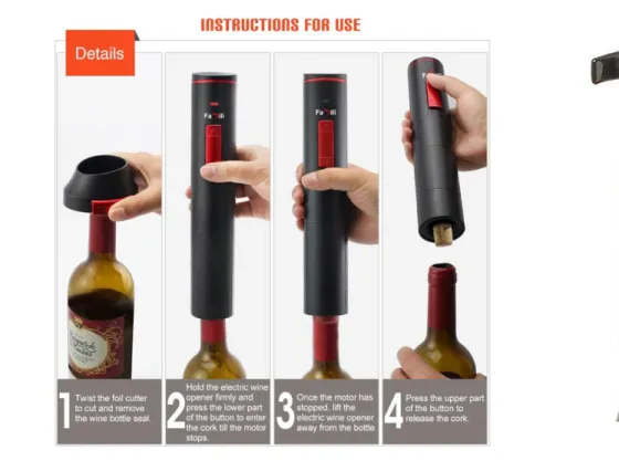
Figure 2.8 (Famili) is a combination of a manual foil remover and an electric cork remover. The electronic components in this device may be a useful addition to our product. The product in Figure 2.9 (WineStuff) is a more simplistic cork remover that only automates the step of inserting the corkscrew into the cork. With both products, the rim of the bottle is attached to the device which helps in guiding the corkscrew through the center of the cork, minimizing corkscrew location error.
FIGURE 2.8.ELECTRIC CORK REMOVER AND FOIL CUTTER FIGURE 2.9.SCREWPULL CORK REMOVER
2.3
TECHNICAL RESEARCH
3
OBJECTIVES
The Center of Effort winery currently lacks a unique attraction to set apart their tasting room experience from the rest of the industry. Instead of using manual wine openers, Bill Swanson, the owner of Center of Effort, would like a decorative, automated, mechanical device to open and pour wine. The device must remove foil from variously shaped wine bottles, remove multiple types of corks, and pour a variety of volumes of wine. The device should be quick and easy to use, match the modern aesthetic of Center of Effort’s new tasting room, and attract and entertain customers.
The boundary diagram shown in Figure 3.1 gives a visual representation of the scope of this project. The blue dotted line is drawn around only the things that we have control over. It excludes those that we do not. The objects that are sitting on the outside edge of the blue dotted line are the things that must be accounted for when designing our product.
FIGURE 3.1.BOUNDARY DIAGRAM ILLUSTRATING SCOPE OF PROJECT DESIGN
Starting from the bottom of the diagram, we will design the base on which our product will reside, but we will not be able to control the table, or location of the table, that the base sits on. The motor shown in the diagram is the representation of the actuator and power source that we do have control over, which will account for the potential use of a wall outlet but will not solely rely on it.
The components that we do have control over include the cutting device that we will use to slice and remove the foil, the corkscrew that will be used to remove the cork, the control panel, the sensor for the volume of wine poured, and the lever arm that lifts the bottle of wine along with the motor that will power each component. Each of these components is within our scope so we may choose and modify them in any way that will result in meeting the design requirements.
3.1
DESIGN CONSIDERATIONS
After collaborating with our sponsor, our project group separated each design consideration into either the “needs” or “wants” category by deciding which specifications are necessary to deliver a successful project, and which specifications would simply improve the overall product, but would not render the product unsuccessful if not incorporated.
Regarding the geometry and ability to transport the device, this product will reside on a tabletop in the Center of Effort tasting room and will only be moved in the case of a wine event. For this purpose, the product will be able to sit on a flat, smooth surface and be able to operate, assuming that the surface is level. The product will be made to fit through a standard size doorway as well as fit into a standard size car trunk for ease of transportation. Additionally, the product will be designed so that two people or less will be able to transport it. It will not be guaranteed to be transportable by a single person as it may limit the capabilities of the product.
The product will not always have access to a wall outlet, so it will run off of a rechargeable battery. It will also have the capability of being plugged into a wall outlet for continuous use in the tasting room. The battery will last long enough for the device to open at least 12 bottles of wine and complete 150 separate pours. We expect this to be a simple function of battery size. A larger battery will be used if the product does not run for the specified number of uses.
Our product will not be designed to hold or maintain more weight than the Center of Effort’s heaviest bottle of wine. Our project team will measure each type of bottle and perform the necessary engineering calculations to come up with an appropriate lifting force. The lifting force will be designed with a factor of safety to be sure that it will not drop any bottles.
The staff members of the Center of Effort winery will be the only personnel operating this machine after receiving training. However, the machine may be accessible to untrained personnel at wine events and will therefore be designed for minimal to zero chance of injury. Additionally, the materials we use to build this product will be chosen only if they are safe to use in a food environment. We will not use any potentially harmful chemicals that will threaten the safety of those in the tasting room should they come close to come in contact with the product.
We had an initial budget of $4,500 to use in the design and manufacturing of this product. The project team created a budget plan optimizing the amount we spent on each phase of the design process. This budget was initially enough to get all of the necessary components, but it did not account for replacing broken parts during testing and therefore pushed us over this limit. Our sponsor had assured our project team that additional funds could be made available, so in order to keep the project moving along, we found it necessary to secure these funds. The specifics of these troubles are discussed in further detail in Section 5.4.
3.2
QUALITY FUNCTION DEPLOYMENT
To ensure that we design for the correct problem and meet the necessary specifications of the product, we began a Quality Function Deployment (QFD) process. Our QFD chart is included in Appendix D for reference. In the QFD process, we first discussed whom the product is for and then separated our sponsor’s wants and needs into items that can be quantified and items that can be qualified. The quantifiable wants and needs are those that can be systematically tested using an engineering process. The wants and needs that can be qualified by observation alone are described as design considerations and are acknowledged through our design process but are not added to the engineering specification list on our QFD chart. The qualified needs were assessed during the testing stage to determine whether the need has been met; the results of these qualifications are discussed in a later section.
Our QFD analysis yielded several interesting results. Our most important engineering specifications were the cork pull force and bottle lifting force. We expected this since both are related to the functional success of our device. Just below these two were factors related to size and portability. The finished device needs to be comfortable to use and portable for offsite events, often where electrical power will not be supplied. Our analysis also showed that low cost was negatively related to most of the other specs; in other words, nearly every area can be improved by spending more money. Although there was nothing particularly surprising in our QFD results, performing the analysis helped our team focus on critical specifications.
3.3
ENGINEERING SPECIFICATIONS AND RISK ASSESSMENT
Table 3.1 on the following page lists the engineering specifications that we tested. For Critical Design Review, we concluded that the lifting force was the engineering specification that would be the most difficult to meet. Some specifications that were considered high risk during Preliminary Design Review were reassessed. Changes to the specifications table between PDR and CDR are indicated with strikethroughs and are explained later in this section.
force to avoid spilling the wine. Finding an appropriate gripper that could vary in radius and keep the bottle from slipping was selected in the ideation process.
TABLE 3.1.ENGINEERING SPECIFICATIONS SPEC
# DPESCRIPTIONARAMETER REQUIREMENTS OR TARGET TOLERANCE RISK COMPLIANCE
1 Product Width 36 inches Max L I
2 Product Depth 48 inches Max L I
3 Product Height 2.5 feet ± 1.5 feet L I
4 Product Weight 25 lbf ± 20 lbf M L A
5 Cork Pull Force 9 lbf Min H L A, T I
6 Lifting Force 4 lbf Min H A, T
7 Operation Time 90 seconds Max M T
8 Noise Measurement 70 dB Max L T I
9 Change in Wine Temp 0 °F ± 2 °F L T
10 Volume Accuracy 5 ounces ± 5% M T
11 Battery Life 12 cork removals and 150 pours Min L A, T
12 Cost $4,500 Max M A
The change in risk for product weight decreased from a medium risk to a low risk because with the design more solidified, it was highly unlikely that the product itself would weigh more than the original specification: the maximum weight being 45 pounds.
The cork pull force was considered a high-risk specification during PDR but was changed to low-risk due to the design of the product. The pull force is contained within the electric corkscrew selected for the current design: the corkscrew uses its own housing to provide the resistance force needed to pull the cork. Therefore, the pull force was not something that our team needed to design a specific part for, and it was not considered in the testing phase. These reasons also explain the change in compliance from analysis and testing to inspection only. As long as the cork was fully removed, the cork pull force would be ignored.
4
CONCEPT DESIGN DEVELOPMENT
The scope of this design requires successful performance of multiple actions: removal of foil, removal of cork, gripping of wine bottle, lifting and pouring of the wine bottle, and sensing pour volumes. Control of these actions should be accessible through a user interface, and all actions should successfully integrate with one another. To develop the conceptual design of this automatic wine opener, we began with ideation of individual actions.
4.1
CONCEPT DEVELOPMENT & SELECTION
Cork & Gear spent multiple weeks performing a variety of ideation exercises to come up with creative ideas that have potential to perform one or more of the necessary actions. Methods included team brainstorming utilizing a white board, sticky notes, and a projector. For brainstorming with a white board or sticky notes, each team member was provided a white board marker or a stack of sticky notes and a pen. Team members were encouraged to add any and all ideas to the board at any time during the session. Using a projector for brainstorming required verbally describing an idea one at a time so that the idea could be displayed on the projector through a single computer.
The marker and white board method proved to be the quickest method to produce the largest quantity of ideas. As a team, we held back on criticizing any ideas, because what might be considered a bad idea often led to the development of a great idea. This effect was amplified when we brought in friends that were much less familiar with the constraints of the project to help brainstorm. The people with outside perspectives came up with ideas that our team may not have thought of due to the increased familiarity with the scope of the project.
After many ideas were generated for each of our six functions, we began to refine each list toward a single concept in several stages. A first pass was taken to quickly remove ideas that were infeasible, unsafe, or outside of our scope. Then, in every list, we developed sets of criteria for comparing concepts in a Pugh matrix. Once each member had time to evaluate the concepts individually, we came together to discuss which ideas to move to the next stage with and which ones to drop. This analysis was helpful in identifying critical design features in some areas. The following sections provide descriptions of the remaining ideas for each concept.
4.1.1
G
RIPPINGFIGURE 4.1PINCER GRIPPER
FIGURE 4.2LINEAR GRIPPER
FIGURE 4.3CONCEPT PROTOTYPE OF LINEAR GRIPPER
FIGURE 4.4BROOM CLIP
FIGURE 4.5BOTTLE HANDLE
4.1.2
F
OILR
EMOVALFIGURE 4.6.EXAMPLES OF CHOSEN FOIL CUTTING CONCEPT
4.1.3
C
ORKR
EMOVALSince a traditional corkscrew removal was requested by the sponsor, the top methods of cork removal included a traditional pull corkscrew, a Waiter’s Helper corkscrew, a Rabbit corkscrew, and an electric corkscrew. Examples of each corkscrew are shown left to right in Figure 4.7 below.
FIGURE 4.7.CORKSCREW CONCEPTS
4.1.4
L
IFTING&
P
OURINGFIGURE 4.8.CONCEPT PROTOTYPE OF ESCALATOR LIFT/POUR
Figure 4.9 shows a “C” track in which the bottom of the wine bottle is placed onto a curved vertical track while the neck of the bottle rests on a pivot point located above the wine glass. The bottom of the wine bottle would be pulled up along the track, thus increasing the tilt angle and pouring the wine into the glass below.
FIGURE 4.9CONCEPT PROTOTYPE OF CTRACK LIFT/POUR
The four-bar linkage device shown in Figure 4.10 is a motor-driven system which lifts the bottle up and tilts it to pour wine into a wine glass. The wine bottle is attached to the four-bar linkage with a hose clamp or other attachment method.
FIGURE 4.10CONCEPT PROTOTYPE OF FOUR-BAR LINKAGE LIFT/POUR
FIGURE 4.11CONCEPT PROTOTYPE OF GYROSCOPIC LIFT/POUR
The last major lifting and pouring idea used three simple motions: linear vertical motion, linear horizontal motion, and rotation. The linear motions would lift and move the wine bottle, and the rotation motion would tilt the wine bottle to pour it into a glass.
4.1.5
S
ENSEP
OURV
OLUMEThe top ideas for sensing the amount of wine poured include load cells, strain gauges, and pressure sensors. Less technical methods involved using a scale, a mechanical pour regulator, a timer and measuring flowrate. These methods were eliminated due to inaccuracies or complexity of the measurement or design.
4.1.6
U
SERI
NTERFACEuser interface will be largely based on the amount of time the team has available after completing the design of the rest of the product.
4.1.7
O
VERALLD
ESIGNI
NTEGRATIONTo successfully open and pour a bottle of wine, all of the actions described above must work together. Three ideas were compared for the overall integration. One idea involved stations in a linear setup. Another idea placed stations around a rotating platform. The third idea utilized one main arm with multiple tools. The arm would be able to rotate different tools over the wine bottle so multiple actions could be performed without moving the bottle.
The Pugh matrix analysis that compares the ideas for each function confirmed our expectations of which ideas would be most appropriate for the project, such as the use of a motorized corkscrew. Although the exact method was still undecided, it was confirmed that the amount of wine would be weighed rather than using a less direct method of determining the volume. With a smaller selection of ideas, a weighted decision matrix was built for each function using the concepts that had passed our Pugh matrix analysis. The criteria for the weighted decision matrix were drawn directly from our engineering specifications and customer needs and wants list and were given weights based on each criterion’s significance in the design. The top idea for each function was chosen and an alternate idea was chosen for those functions that proved to have several ideas of similar suitability. The results of our decision matrix analysis are summarized in Table 4.1, and the full weighted decision matrix for each concept can be found in Appendix E.
4.2
PROTOTYPING
4.2.1
C
ONCEPTP
ROTOTYPESFollowing completion of analysis, we began prototyping the best options of each function produced by the decision matrices. Although the best options had been decided for each function, only the lifting, pouring, and cork removal functions were prototyped. These functions were chosen for prototyping because they had more challenges in terms of functionality and were the basis of one or more of the other function. Material availability also played a factor in choosing the early prototypes.
4.2.2
P
ROOF-
OF-
CONCEPT TESTINGTABLE 4.1.LEADING CONCEPTS FROM IDEA CONVERGENCE
FUNCTION LEADING CONCEPT ALTERNATIVE
GRIPPING Broom clip Bottle Handle
LIFTING &POURING Four-bar linkage Rotating platform with stations
USER INTERFACE Mechanical switches -
FOIL REMOVAL Cap cutter -
CORK REMOVAL Electric corkscrew -
SENSE WEIGHT Pressure sensor Load cell
FIGURE 4.12FOUR-BAR LINKAGE PROTOTYPE
The second proof-of-concept prototype was the uncorking tower. An electric corkscrew was purchased for this prototype and integrated into a mechanical frame. This structure included the attachment to the electric corkscrew, the tower that secured the linear actuator, and the base as shown in Figure 4.13. All of these components were also laser cut from plywood. The prototypes helped prove that we could remove the cork and pour its entire contents.
4.2.3
R
ESULTS OFC
ONCEPTT
ESTING ANDR
EDESIGN
FIGURE 4.13ELECTRIC CORKSCREW PROTOTYPE
Due to the difficulties of the four-bar linkage, we went back to our foam core prototypes and decided that a simple lift and pour method would be easier to design and implement. Additional brainstorming led us to the idea that we have chosen to move forward with.
4.3
CHOSEN CONCEPT QUALIFICATIONS
The overall concept that we chose incorporates only the original cork removal prototype that we developed. A design allowing accurate pouring and minimal spilling were the main focuses for this decision. Bottle pour angles were experimented with, and a summary of these tests and calculations can be found in Appendix F. Programming the device itself would prove to be one of the biggest challenges. Experimenting with the programming was necessary to get the motions down correctly. Thorough testing was performed to verify the functionality of the product as a whole.
The chosen concept already fits many of the specifications discussed in Chapter 3. The product fits through a standard doorway and into the back seat of a small sedan. Transportability was an important goal in this project, as the device will be taken to wine events. The preliminary estimate for the product weight was 45 pounds maximum.
An additional aspect that made this design attractive was that very few modifications would be needed in order to open and pour various types and sizes of bottles. The linear actuator allows the cork and foil removal to be independent of height and bottle shape.
5
FINAL DESIGN
5.1
DESIGN DESCRIPTION
5.1.1
O
VERALLL
AYOUTThe novel wine opener performs four major functions: removes the foil from a wine bottle, removes the cork, pours the wine into a glass, and senses the amount of wine in the glass to produce accurate pour sizes. The opener is controlled by a user interface located on the front angled panel of the base. The layout of the design with all of the integrated components is shown in Figure 5.1.
FIGURE 5.1ISOMETRIC DRAWING OF WINE OPENER
5.1.2
S
UBSYSTEMSFIGURE 5.2GRIPPER COMPONENTS
Foil removal begins when the main tower rotates until the foil cutting tool arm is centered over the wine bottle. The linear actuator lowers the gantry system until the floating gantry rests on the top of the bottle. The foil cutting mechanism consists of two linear servos with serrated commercial foil cutter blades attached. The servos mount to a platform, which rests on top of the bottle, and squeeze the blades into the foil. Simultaneously, a servo motor rotates the platform 360° to cut the foil. Once fully cut, the linear actuator lifts the tool up and away from the bottle, removing the foil with it.
The first iteration of the foil removal design, shown in Figure 5.4, results in a cut at a fixed distance from the top of the bottle to the cut location. The top plate mounts the linear servo motors for adjusting the blades and serves as a structural backstop, thus allowing the blades to cut in the same spot as they rotate about the bottle. The blades used have serrated edges because they have been proven to be more effective than straight edged blades through the testing process.
FIGURE 5.4FOIL CUTTER DETAIL,FIRST ITERATION
The original iteration of the foil cutter got the main idea across: the two linear servos and the rotational servo would squeeze the foil and rotate to cut. However, this version needed some improvement as the brackets that held the blades were not structurally supported, giving them a lot of wiggle room, and thus did not cut the foil effectively. They would bend in the vertical direction and also out to the sides (Figure 5.5), prompting the next iteration of the foil cutter, shown in Figure 5.6.
FIGURE 5.6FOIL CUTTER,SECOND ITERATION
This version of the foil cutter stabilized the brackets vertically and horizontally by putting screws and bolts through the center of the arms, forcing it to follow the desired path. This led to much more successful force on the neck of the bottle. However, this version would get caught on the bolts quite often, preventing the blades from either reaching the bottle or preventing them from returning, making it an unreliable design. This led to the 3rd iteration shown in Figure 5.7.
FIGURE 5.7FOIL CUTTER,FINAL PROTOTYPE
FIGURE 5.8FOIL CUTTER,FINAL DESIGN DETAIL
Positioning the corkscrew is similar to positioning the foil cutter in that the linear actuator tower rotates the cork removal tool arm directly above the mouth of the bottle. The linear actuator lowers the tool arm until the corkscrew rests on top of the cork. The corkscrew is an off-the-shelf Houdini electric corkscrew wired to be controlled remotely. Controlling the motor with a microcontroller and using an external power supply allows us to achieve more torque by running it at its maximum voltage/current rating instead of relying solely on the battery power it uses during traditional use. Using this corkscrew removes the need to implement a pull force on the cork as was discussed previously, because the corkscrew uses its own housing for the resistance force and pushes against the bottle to remove the cork. When the electric corkscrew’s full travel into the cork is completed, it continues spinning to remove the cork steadily. This corkscrew also has the ability to back out the cork from the corkscrew on its own by reversing the rotation.
FIGURE 5.9LOAD CELL AND WINE GLASS PLATE
FIGURE 5.10DRAINAGE CUTOUTS
The operation of the user interface is as follows: The user must turn the lockout keyswitch to enable power to the machine before initializing the microcontroller and the motors using the power toggle on the front panel. The cork and foil toggles can be switched on to indicate which functions the user would like to take place. If both are off, the machine will simply pour the wine. The pour size buttons function as the start button for that pour; the machine will start will the cork and foil functions if the toggles are on before proceeding to the pour. If at any time the machine starts to malfunction, the emergency stop button labeled “Stop” can be pressed to allow the machine to slowly return to a safe position and power off. The user must then switch the power toggle off and on again to continue operation. For more detailed information on how to run the machine, an operator’s manual has been provided and can be found in Appendix N.
5.1.3
E
LECTRICALS
YSTEMSOur device will be actuated mechatronically with a network of servo motors, sensors, control boards, and a microcontroller. The Arduino Mega is our controller of choice, since many hardware and software solutions already exist for it. Smart servos are used for all motion except the corkscrew and main tower, where precise position or velocity control is not necessary. A load cell measures the volume of wine poured, and mechanical switches register user inputs.
The load cell, two rotational servos, and stepper motor all interface with our microcontroller through intermediate driver boards. We designed a custom circuit board to assist in routing power and data cables (Figure 5.12). The pouring motor interfaces to the Arduino through a tri-state buffer chip, seen on the right side of the board in the below image. A carrier board for an A4988 stepper motor driver chip (the green board) plugs directly into this board as well. The linear servos in the foil cutter are the only motion elements connected directly to the Arduino for control but pass through the board to support a standard three-pin servo header.
FIGURE 5.12.CUSTOM CONTROL BOARD
All of the user interface switches plug directly into digital input pins on the Arduino. The LEDs are controlled separately on 12-volt power. The toggle switches use a synchronous circuit, meaning that they turn on when the switch is in the “on” position. This makes it easy to tell when a specific feature has been selected, or when the main controller power is on. The button LEDs are connected to a power relay board which is driven by the Arduino. This allows the LEDs to be switched on and off independently of button presses, which is useful for displaying status information.
The whole device will be powered from an external 12-volt supply, using a 5.5mm barrel jack connector. This allows us to use commercially-available power supplies and batteries in our design, fulfilling specification #11 in Table 3.1 The foil cutter requires a small subsystem on 6 volts, but inexpensive and reliable step-down converters exist for this purpose. The Arduino additionally regulates its own 3.3-volt and 5-volt supplies for sensors and data. Figure 5.13 provides an overview of the power and data connections between our primary electronic components.
FIGURE 5.13.WIRING LAYOUT SCHEMATIC
5.1.4
S
OFTWARED
ESIGNFIGURE 5.14.MASTER STATE DIAGRAM
The foil removal and cork removal states will contain many sub-states to control specific motor movements, indicated with (1) and (2) on the flowchart. Unloading of the removed cork and foil are sub-states that happen automatically during the opening process. These sub-states, along with the master state diagram and pouring controller block diagram, are all provided in Appendix G.
The pouring state, marked with (3), will take the form of a closed-loop PID (Proportional, Integral, Derivative) controller. The controller accepts a desired pour volume from the microcontroller, selected by the user, and pours an output volume into the wine glass. Involved in this system are the pouring and weight-sensing hardware (load cell); the pouring motor is given a signal to tip the bottle and pour wine, while the sensor under the wine glass provides feedback on how much wine has been poured. A digital filter was used on the data read back from the load cell as the data was too noisy, mainly because of the wine splashing in the glass, to keep the motor in steady motion. The system is capable of recording the amount of wine already poured in order to estimate the remaining volume in the bottle. Figure 5.15 shows our block diagram design for this controller.
FIGURE 5.15POURING CONTROLLER BLOCK DIAGRAM
load cell captures the final pour weight and subtracts it from the remaining volume. This value is later used to incrementally adjust the upper pouring limit as the bottle is emptied.
Because the Dynamixel motors communicate over 1-wire serial TTL (transistor-transistor logic), a special interface such as the smart servo shield must be used. This works fine for the AX-12A servos, but the MX-64T servo uses a slightly different control table. The least expensive route to working with the MX-64T was through a tri-state buffer (such as the 74LS241N in our design), which put both the transmit and receive signals onto the same wire. The Dynamixel_Servo library, available through the Arduino library manager, was used to manage this interface, although we were unable to read data back from the motor.
Programming of the Arduino microcontroller will be carried out in C++ over the built-in USB port. This will make updating or modifying the code easy, as well as allow for the Arduino to be easily replaced. A programming guide is included with the Operator’s Manual for guidance in modifying or updating the control code.
5.2
ANALYSIS AND RESULTS
The corkscrew and its housing were originally going to be manufactured by us, which required knowledge of the force needed to remove the cork. However, the design was changed to integrate a commercially-available Houdini electric corkscrew that is already designed to pull corks, removing the need for us to incorporate a pulling force into the design. Testing revealed that the corkscrew was sufficiently powerful to engage and pull every cork in our test cases.
One concern that we had during the development of the foil and cork removal operations was the tower stepper motor’s ability to pull the cut foil off of a bottle, while also lifting the weight of the floating gantry. Although the forces were not analyzed, our tests showed that the stepper is more than powerful enough to pull the foils off, unless the foil is incompletely cut or scored.
The original plan to rotate the bottle was to grip it in the middle and rotate it around a central point. The original calculations for this provided a necessary torque of about 340 oz-in. However, the new design rotates the bottle around the neck, increasing the necessary torque. The new calculations assume that the bottle is 3.5 pounds when full, and that its center of gravity lies about 8 inches down from the gripping point on the neck. The gripper assembly is assumed to be about 2 pounds and to have a center of gravity 10 inches below the gripping point. All of these values were chosen to be of an extreme case, and result in a required torque of 780 oz-in. The Dynamixel MX-64T motor provides 850 oz-in at 12V. Detailed hand calculations for the required torque can be found in Appendix H.
FIGURE 5.16REMOVABLE SAFETY SHIELD
Using the motor to pour an appropriate amount of wine depends both on the angle of the wine bottle and the current amount of wine in the bottle. The pouring controller reads both the current volume and the rate of change of the volume (pour rate) and adjusts the bottle angle based on this information. The analysis suggests that wine will begin pouring just over 80 degrees from the horizontal and will finish pouring just under 110 degrees from the horizontal; this is illustrated in Table 5.1. Between these two angles, there is a linear relationship which can be seen in Figure 5.17. The complete datasheet is located in Appendix F.
TABLE 5.1POURING ANGLES
We implemented a rudimentary proportional controller using the pour rate as the input signal, and using the volume reading as the cutoff trigger. We opted not to develop a full PID controller partially due to the increased complexity, and partially due to difficulties in accurately working with the motor and load cell. The final revision of this controller features a number of tunable parameters and provides a repeatable error of ±10%. This does exceed our original
specification of ±5% error, however. Potential ways of reducing this error in the future is discussed in a later section.
5.3
COMPONENT, MATERIAL, AND GEOMETRY SELECTION
Each of the wine opener functions incorporate purchased and custom manufactured parts. Commercially available parts have been used where possible, and simpler features were chosen to keep manufacturing time to a minimum.
V-slot beams and ¼” aluminum plates are used throughout the design as structural materials. V-slot is used as the main support for both towers in our design as well as the tool arms. Our team chose this material for its strength and versatility in prototyping. Waterjet-cut aluminum plates are used for adapting V-slot to other components as well as the electronics housing. This material was chosen for appearance, weight, and simplicity of manufacturing. Additionally, we were able to model and prototype these parts with inexpensive laser-cut acrylic sheets.
The two main components of the rotating tower are a linear actuator from OpenBuilds and a Dynamixel AX-12A smart servo located in the base. The linear actuator was selected because it is tall enough to lift the components above the wine bottle and sturdy enough to lift both components. The OpenBuilds part system is also easy to modify and integrate with the rest of our design. The smart servo was chosen for its positional control, which is crucial for aligning tools with the wine bottle.
high-strength nylon. The cutter blades were taken from an existing foil cutter, chosen for their effectiveness and ease of replacement.
The corkscrew system features an electric corkscrew and a custom mounting bracket. The corkscrew is a commercially-available model that has been tested and proven to work. An aluminum housing secures the corkscrew to the gantry, allowing for easy replacement of the corkscrew. This sleeve consists of a piece of pipe, acting as a sleeve, welded to square tubing.
The pouring and gripping function has several unique components. A Dynamixel MX-64T smart servo is responsible for the pouring motion. This motor has similar features to the AX-12A servos in the tower base and foil cutter, but provides the torque required for lifting a full bottle of wine. Section 0 covers the analysis that led to the selection of this motor. The bottle holder arm comprises an aluminum plate backbone, the neck clamp and its brackets, and the pivot standoffs. The backbone is made from waterjet-cut aluminum. The neck clamp was purchased. The pivot standoffs and neck clamp bracket were machined from aluminum rod and angle stock. The gripper curve was manufactured from a block of aluminum that we outsourced for CNC machining. Finally, the gripper sleeve is made from clear polycarbonate 4” diameter pipe, chosen for visibility of the bottle label.
The weight sensing task uses a micro load cell and its fixturing. This component was changed from a pressure sensor for easier mounting and integration since the load cell comes with tapped holes for mounting. A plate is attached to one end of the load cell for holding the wine glass. Standoffs connect the plate to the load cell and the load cell to the base plate, creating the height necessary for the weight sensing plate to match the level of the electronics box’s upper surface.
The electronics box is made from aluminum sheet stock and was manufactured by Protocase. This box, as well as the external-facing aluminum components, were all powder coated to protect the aluminum and enhance the aesthetics of the device. Powder coating results in a better-looking finish around welds and sharp corners than anodization, the other finishing process that we considered.
Main power is conducted through 16-gauge wire. Although the device has not used more than 5 amps of current, we designed the system for a maximum power draw of 10 amps. Some of the peripherals use 18- and 20-gauge wire where appropriate, since no individual component draws more than 3 amps.
5.4
COST ANALYSIS
At the time of CDR, the budget estimate indicated the spending would not exceed the initially allotted funds of $4,500. $1,933.22 had been spent at that point, and the final design cost was estimated at $3,026 including shipping costs. The final Novel Wine Opener prototype exceeded the initial project budget because of underestimated part costs, replacement for components that broke unexpectedly, and rushed shipping costs. The final cost of the design process was $4,960. However, the total cost associated with the final build of the Novel Wine Opener is $3,050.
Prototyping costs totaled approximately $1900. These costs include prototyping materials such as wood and acrylic, prototypes of preliminary design iterations, foil cutters, glue, and fastening hardware. In the CDR report, shipping costs for this project were estimated at $400, which is approximately the total amount that was spent.
The manufacturing of the electronics box, which was outsourced to Protocase, cost much more than originally anticipated. Initially, the box was estimated to cost around $300. The functional and aesthetic design of the electronics box required sheet metal bending, seam welding, powder coating, and silk screening. Protocase was able to perform all of these processes, however the total cost of the box ended up being close to $600—13% of our initial budget for a single part. The gripper neck clamp was also more expensive than expected. A Stafford shaft collar was selected for this neck clamp and the expected cost was between $10 and $30—typical prices for a heavy-duty collar bracket. However, the shaft collar cost $117 because the collar consists of two separate halves attached by a hinge on one side whereas most shaft collars tighten and loosen, but do not open at a hinge – a feature necessary for the design of the gripper.
Three weeks prior to Cal Poly’s Engineering Senior Project Expo, an unexpected electrical short occurred breaking multiple electronic components necessary for operating the foil cutter, cork remover, and rotating tower. Because the deadline for the project was quickly approaching, the broken components needed to be replaced as soon as possible. Replacement parts were purchased with rushed shipping, adding an extra expense, in addition to the parts themselves that would not have otherwise been required. This rushed order expended most of our remaining funds. A $500 increase in funds was requested from Mr. Swanson and approved, allowing us to finish the project with the necessary parts.
finishing was well worth the aesthetic result, which matches the color scheme of the Center of Effort tasting room.
Some costs were conserved by taking advantage of manufacturing resources available on Cal Poly’s campus rather than outsourcing all parts to vendors. For example, there was an option between sending a handful of parts to a CNC shop in town or machining them by hand in Cal Poly’s Mustang 60 and Aero Hangar Machine Shops. The latter option was chosen, saving us a total of $460. Additionally, most of the Novel Wine Opener’s aluminum parts were manufactured with the water jet in Cal Poly’s Industrial Technology (IT) Machine Shop as opposed to outsourcing to a machine shop in San Luis Obispo, which saved approximately $300.
A full cost breakdown by part can be found in the Bill of Materials in Appendix I, and all budget and purchasing details for stock parts and vendors can be found in Appendix M.
5.5
SAFETY, MAINTENANCE, AND REPAIR CONSIDERATIONS
5.5.1
S
AFETYSeveral steps were taken to minimize the safety risks inherent to the wine opening device. The foil cutting blades and the corkscrew are the main sharp objects that have the potential to injure someone. However, each of these products are internally located, meaning other components are blocking most access to these objects. When these components are not in use, they are retracted to their most inaccessible position. Although this does not completely eliminate the potential for injury, this product does not have any fast moving or spinning parts that could seriously cause harm. Additionally, the product will only be used by employees of Center of Effort who will be trained on the use of the machine prior to working it.
Other potential concerns include the pinch points around the main linear actuator tower and the pouring tower. A clear acrylic safety shield was designed to eliminate the possibility of someone placing their fingers between the gripper backbone and the pouring housing on the downswing of the bottle. Additional reasons for incorporating this safety mechanism were discussed in section 5.2.
The operator’s manual provided in Appendix N incorporates warnings about these pinch points but there are not any automated safety mechanisms. A complete list of potential hazards that were designed for can be found in Appendix J.
5.5.2
M
AINTENANCESignificant maintenance is not expected for the Novel Wine Opener. However, there are two areas of concern: the foil cutting blades and the rubber caps attached to the tightening screws to hold the bottle in place. Firstly, the specific blades used in the product are serrated blades taken off of a Dual Blade Wine Foil Cutter by HQY. The foil cutter is designed so that the blades will be replaceable, but the frequency at which this will be necessary is unknown. Secondly, the rubber on the tightening screws has the potential to wear out over time. Wear out is not expected to happen frequently, but the specifics of replacing these parts will be included in the Operator’s Manual (Appendix N).
modified corkscrews will be included in the replacement materials that will be delivered to our sponsor along with the Novel Wine Opener. Further details on how this corkscrew was modified are provided in Section 6.4. A guide for modifying the corkscrew as well as replacing it is included in the Operator’s Manual.
5.5.3
R
EPAIR6
MANUFACTURING PLAN
6.1
GRIPPER
The gripper, shown in Figure 6.1, consists of a transparent acrylic sleeve that supports the base of the bottle, a clasping mechanism that secures the neck of the bottle, and a support mechanism that attaches the gripper to the pouring tower.
FIGURE 6.1.GRIPPER ASSEMBLY
A 4” acrylic rod section, a 12” x 12” acrylic sheet, and adhesive glue must be procured in order to manufacture the base sleeve of the gripper. The acrylic sleeve was cut to the proper length using a A 4” acrylic rod section, a 12” x 12” acrylic sheet, and adhesive glue were procured in order to manufacture the base sleeve of the gripper. The acrylic sleeve was cut to the proper length using a horizontal saw, and two holes were drilled on opposite sides of each other. The acrylic sheet was laser cut to obtain a circular gripper sleeve base with drainage cutouts. The convex rubber insert was procured from Shapeways in order to create a raised center for the wine bottle punt to rest around. The rubber bottom provides more friction to resist the rotational slipping of the bottle during the operation of the machine. The sleeve base, sleeve tube, and convex insert are attached using adhesive glue.
A steel collar hinge [B110] is used to clasp the neck of the wine bottle. Holes were drilled into this collar hinge to enable attachment to the pouring mechanism via the custom L-bracket [B101].
that of two knurled head thumb screws [B108]. These thumb screws were screwed inside of the custom screw rotational inserts. Once the thumb screws were inserted through the acrylic sleeve and the ends of the U, the rubber end caps were attached to the ends of each using superglue. Inside of the neck clasp, two 3D printed rubber inserts [B114] were inserted. These rubber inserts squeeze the neck of the bottle and resist slipping vertically and rotationally. These inserts were procured and glued to the interior surfaces of the neck clasp.
6.2
LINEAR ACTUATOR TOWER
The linear actuator tower consists of a manufactured mounting plate [B201], turntable bearing [B202], turntable motor [B203], linear actuator [B206], and floating gantry [207]. The mounting plate, turntable bearing, and turntable motor bolt together to create a rotating base (Figure 6.2). The linear actuator connects to this base with additional V-slot [B102], procured corner connectors [B103], and water jet cut 2-hole brackets [B205] and extends through a hole in the electrical box as seen in Figure 6.3.
FIGURE 6.2ROTATING BASE FOR LINEAR ACTUATOR
FIGURE 6.3LINEAR ACTUATOR EXTRUDED FROM ELECTRICAL BOX
needs. After these parts were machined, the whole assembly was put together with angle brackets [103], L-brackets [204], and fasteners.
The linear actuator’s floating gantry [B207] is the location where the foil cutting and cork removing tool arms attach. The tool attachment arms are made of procured V-slot [B102] and square tube [B412, B501] for the foil cutter and corkscrew, respectively. These arms connect to the linear actuator gantries with L-brackets [B204], M5 flat nuts and M5 bolts.
6.3
FOIL CUTTER
The foil cutter is the device that has gone through the most design iterations since CDR. The new foil cutter, shown in Figure 6.4, consists of a rotational servo motor [B203], two linear servos [B402], two serrated blades [B405], a rotating top plate [B413], a rotating bottom plate [B401], and two blade holders [B403] all manufactured or procured, and mounted to the foil cutter tool arm.
FIGURE 6.4.FOIL CUTTER WITHOUT HOUSING
The motor mounts to the tool arm using the motor mount plate [B414]. The motor shaft attaches to the rotating plate with procured fasteners. The rotating plates were made from 1/8” thick aluminum and were water jet cut. Two linear servos are sandwiched between the plates using fasteners. Both servos are attached to their own foil cutter bracket [B403]. Each servo is inserted into a hole in the foil cutter arm and is secured with an M3 bolt. The foil cutter blade holders [B403] were purchased from Shapeways and made from SLA Nylon. A serrated blade [B405] is attached to each holder using screws that are included with the purchased blade.
6.4
CORK REMOVAL
FIGURE 6.5.HOUDINI ELECTRIC CORKSCREW
FIGURE 6.6ELECTRIC CORKSCREW INTERNAL COMPONENTS
The pink wire connected to the switch and the red wire connected to the motor were cut where the two wires connect to the button. The second red wire, which was connected to the battery terminal, and the two black wires were completely removed. All of these wires are shown connected in Figure 6.7 and disconnected in Figure 6.8.
FIGURE 6.8CORKSCREW CUT AND REMOVED WIRES
A hole was drilled into the black housing in the location shown in Figure 6.9. This hole allows wires to be routed out of the cork remover and into connection with a motor driver.
After the whole was drilled, the cut ends of the pink and red wires were stripped and soldered to new wires. The soldered connections were covered in heat shrink, and the ends of the new wires were stripped and covered with quick disconnect terminals. A diode was soldered to the pink and yellow wires connected to the switch. The white band of the diode faces the yellow wire. The switch connections are shown in Figure 6.8. After the wires were re-soldered and the diode was added, the new wires were routed through the drilled hole, and the motor and springs were repositioned inside of the black housing, as shown in Figure 6.10.
FIGURE 6.10CORKSCREW HEAT SHRINK AND QUICK DISCONNECT TERMINALS
The wires connect to a motor driver chip [B618] (housed in the electronics box), which allows the rotation of the corkscrew to be controlled with code and an Arduino microcontroller, rather than by physically pressing a button. The two black housing pieces were screwed back together. The modified electric corkscrew is shown in Figure 6.11.
See Section 6.8.3 for the manufacturing of the cork remover housing.
6.5
POURING
The pouring tower, shown in Figure 6.12, consists of a MX-64T motor [B105], tower structure, and a gripper with structural backbone as described in Section 6.1. The backbone is made of two pieces, a vertical member [B104] and a U-curve [B107]. The tower structure is made of procured linear rail base V-Slot [B103]. The only design change from CDR for this structure is that the mounting plate for the motor is now integrated into the housing. The gripper backbone is bolted to the motor horn of the pouring motor through two spacers [B115]. These spacers were added after CDR to space the gripper far enough away from the pouring housing to prevent scraping. The whole tower is mounted to the base of the electrical box using 4 aluminum angle brackets [B103].
A small stopper peg was initially going to be included to stop the bottle from hitting the wine glass and knocking it over. After testing the pouring motor and the mechanism, the peg was determined unnecessary. However, the space between the pouring tower and gripper was determined to be a pinching hazard for public use. Because of this, a removable hand guard [B116] was added to prevent users from sticking their fingers into a pinch point area during pouring.
FIGURE 6.12POURING TOWER WITHOUT HOUSING
6.6
SENSING WEIGHT
FIGURE 6.13.SENSING WEIGHT
The circular plate was waterjet cut out of 6” x 6” x 1/8” aluminum. The load cell connects to the circular plate via 6 aluminum standoffs [B803, B804] (Figure 6.14), placing the aluminum plate level with the electronics box.
FIGURE 6.14WINE GLASS PLATE ON STANDOFFS
6.7
USER INTERFACE
FIGURE 6.15.USER INTERFACE
6.8
HOUSING
The wine opener housing consists of three cylindrical covers for the rotating tower, foil remover, and cork remover. A semi-circular cylinder houses the pouring tower, and an electrical box covers all of the electrical equipment. The following sections provide manufacturing details for each housing. Each housing component was powder coated flat black after manufacturing was completed.
6.8.1
R
OTATINGT
OWERH
OUSINGThe rotating tower housing, shown in Figure 6.16, was made out of a 7” diameter aluminum tube and a sheet of 1/4” aluminum [B210]. The tube was cut to a length of about 22.5” using a mill. Two 12.25” by 1.4” slots were cut 180 degrees apart from the top of the cylinder. The slots were cut with a mill and allow the foil cutter and cork remover arms to extend out of the housing.
FIGURE 6.16ROTATING TOWER HOUSING
degrees from each other, which mate with the slots in the cylinder as shown in Figure 6.17. The full circular piece was connected to the two hollow pieces using L brackets [B204] to form a full cap for the cylinder. The full circle rests on top of the cylinder, and the entire cap fastens onto the cylinder with L brackets.
FIGURE 6.17ROTATING TOWER HOUSING CAP AND CYLINDER MATE
6.8.2
F
OILC
UTTERH
OUSINGThe foil cutter housing, shown in Figure 6.18, was made out of a 5” diameter aluminum tube [B409] and 0.25” aluminum sheet. A 5” diameter circular plate [B410] was cut out of the aluminum sheet with a water jet. The tube was cut to about 5.25” in length and a 3.85” by 0.825” slot was cut starting at the bottom of the tube with a mill. The circular plate was welded onto the top of the tube, and the welds were sanded down to be flat. The foil cutter housing connects to the foil cutter with L brackets [B204]. The arm that connects the foil cutter to the rotating tower is housed with a square aluminum tube [B412] cut to about 3.25” in length. This arm mates to the cylinder of the housing with L brackets. A thin sheet of aluminum [B411] fastens below the arm to cover the rest of the slot and the internal foil cutter components from view.
6.8.3
C
ORKR
EMOVERH
OUSINGThe cork remover housing was made out of 1/4” aluminum sheet, a 2.5” outer diameter circular aluminum tube [B502] with a 0.065” thickness, and a 1” by 1” square aluminum tube [B501] with a 0.125” thickness. Two 2.5” diameter circles [B503, B503] were cut out of the aluminum sheet using a water jet cutter. One of the circles had an additional circle cut out of the center of it, leaving a 0.13” thickness around the edges. Two holes were drilled into the solid circle and counter-bored to accommodate 0.08” diameter screws. Four holes were drilled and counter-bored into the second water jet piece to accommodate 0.10” diameter screws. The counter-bored piece is shown in Figure 6.19.
FIGURE 6.19CORKSCREW COUNTER-BORED HOLES
The counter-bored holes line up with the threaded holes in the electric corkscrew used to secure the silver housing onto the black housing. A couple of these holes are shown in Figure 6.20.
FIGURE 6.20CORKSCREW HOLES FOR HOUSING CONNECTION
circular tube with screws, totally enclosing the corkscrew. The cork remover housing is shown in Figure 6.21.
FIGURE 6.21CORKSCREW HOUSING,UNFINISHED
6.8.4
P
OURINGT
OWERH
OUSINGFIGURE 6.22POURING TOWER HOUSING