Effect Of Expansion Joints On Dynamic Analysis Of Structure
Dr.B.Sujatha1, B Anil Kumar2
1PG Scholar, Pydah College of Engineering, Kakinada, AP, India. 2Assistant Professor, Pydah College of Engineering, Kakinada, AP, India
.
Abstract:
For convenience, the scope of the Committee's study was limited to expansion joints that separate structural frames of buildings in order to relieve excessive temperature ‘inducedstresses. The practices and procedures suggested herein are considered to be sound and should guide the designer in producing a more efficient building system than in the past. Also, they have been based for the most part on experience and educated judgment. Tem-premature fluctuations also effect dimensional changes in the vertical direction and the performance of the nonstructural building components; while such effects are not considered in this report,. They cannot be ignored during design. Execution of the most efficient design with respect to the total effects of temperature changes on building performance requires criteria developed on a data base more technically sound than exists at present. Thus, research should be undertaken immediately to provide urgently needed information and data that: I. Reflect building damage directly attributable to temperature fluctuation. permit the correlation of ambient temperature with temperatures of building components (structural and nonstructural) at the periphery and within buildings for different building types and materials. Permit the correlation of ambient temperature fluctuations with temperature gradients existing within building components under different conditions of exposure and insulation of these components. Also needed are analytic and experimental investigations that will lead to the correlation of stresses in the various building components with the different patterns of temperature fluctuations and gradients and with the different types of assembly component (connectors). Buildings supported on masonry walls require special examination since effects of temperature changes on the performance of such buildings will vary according to the type of masonry material or combinations of material used. Each type and combination should be investigated with respect to construction details, connections of walls to horizontal and vertical components (roofs, floors, walls, and partitions at right angles), optimal spacing of joints, and extent of joints.
Introduction
1.1 Definition Of Expansion Joint
The term “expansion joint” as used refers to the isolation joints provided within a Building to permit the separate segments of the structural frame to expand and contract in response to Temperature changes without
adversely affecting the building's structural integrity or serviceability.
Designing for the movement of building components is an important part of architectural detailing. The movement can be the result of temperature changes, imposed loads, settlement, or other causes. Building expansion joints are used to cover the space between components, and provide a barrier to the exterior.
Expansion joints can follow complicated paths along varying materials. Copper is an excellent material for such joints, since it is easy to form and lasts a long time. When detailing an expansion joint for a specific application, it is important to consider the magnitude and direction of movement. Some dimensions of details presented in this section are based on the expected maximum amount of expansion (labeled "E" in the details). Most expansion joints are optimized to accommodate movement in only one direction. Their ability to accommodate movement in other directions varies with their design. The designer should review the details and select the appropriate design based on particular requirements.
One issue that must be addressed in the proper design of expansion joints is the height of curbs. This dimension depends largely on whether or not a cant strip is used at these locations. Normally, the minimum recommended curb height, measured above adjacent roofing, is 8 inches. However, if a cant strip is used, this dimension must be increased. If a typical 4" cant is used, the height of the curb should be a minimum of 10 inches above the adjacent roof. This leaves room for a minimum counter flashing lap of 4" and 1" to 2" space between the cant and the counter flashing.
Ceramic and stone tiles can be subjected to a variety of strains and stresses caused by movement in the tiled surface, leading to tiles bulging, cracking or becoming detached from the substrate. Movement joints compensate for the movement of tiles which extends down through the tiles, the bed and screed layer below. Without them the shear stress builds up between the tile and the screed, causing deboning, bulging and cracking. Therefore these stress-relieving joints are an essential part of any tiling installation, and should be incorporated at the design stage.
tile field should be no more than ten meters in each direction for floors - but in practice, depending on the individual application, it tends to be between five and eight metres for floors, and every three to four-point-five metres on walls.
Installing the appropriate movement joints in line with those recommendations, will prevent tiles from cracking, bulging and debonding. And by "appropriate," that means one which can do what is being asked of it. There are different widths of pre-formed movement joints, and the correct width and material - brass, aluminum, stainless steel or PVC - must be specified to take thermal movement into account.
The amount of movement that can be absorbed and therefore the degree of protection given by the joint -depends on the size of the profile and the compressible material used. Pre-formed surface joints will usually accommodate movement up to 20% of the movement zone width. A 10mm joint will extend and compress by approximately 2mm. One of Schlüter's stress relieving movement joints, the Schlüter DILEX-KS, has a movement zone of 11mm, will accommodate up to 2.5mm of tile movement. Because there are specific movement joints for specific types of application, most tiling failures are caused by using joints that aren't suitable for what is being demanded of them. There are many situations, each with their own technically engineered solution in the form of the correct joint.
Very often the problem can be caused by using the wrong joint-one that is not able to meet the requirements that are demanded of it. Generally aluminium is ideal for commercial use; with brass and stainless steel needed for heavy duty commercial and industrial projects such as warehouses, production facilities and airports, and where the tiled surface is cleaned by a scrubbing machine, or where there are rolling loads such as pallet trucks and metal-rimmed trolleys. Stainless steel is also ideal in places like laboratories and food processing plants where chemicals are used. PVC can be used for residential and medium duty commercial applications including offices and swimming pools, and areas subject to light mechanical loading such as showrooms and car dealerships.
Many calls to Schlüter's technical support service refer to application problems, where no joint or the wrong joint has been used. Other callers seek advice before the work is carried out - and we would say that it's in everyone's best interests to ensure that ceramic and stone tiles are installed with the correct movement joints.
Prevention is always better than the cure which is why Schlüter is always happy to advise on the requirements of individual projects, as well as delivering a variety of training courses on the use of movement joints.
2.1 Expansion Joint
The normal practice in runways, bridges, buildings and road construction is to provide expansion joints between cutting slabs of reinforced concrete at designing intervals and at intersections with other
constructions. These joint filers are then covered with sealing compounds.
Concrete expands slightly when the temperature rises. Similarly, concrete shrinks upon drying and expands upon subsequent wetting. Provision must cater for the volume change by way of joint to relieve the stresses produced. An Expansion joint is actually a gap, which allows space for a building to move in and out of. The movement of the building is caused most frequently by temperature changes, the amount of expansion and contraction of building depends upon the type of material it is constructed out of. A steel framed building will move by a different amount then a concrete framed one. In case of a small building, the magnitude of expansion is less and therefore, no joint is required either in the floor or roof slab. But in case of the long building, the expansion is very large and may be as much as 25 mm. Therefore, buildings longer than 30 m are generally provided with one or more expansion joints.
Having successful determination the predicted movement along the three principal axis of the Expansion joint gap, the designer and Specifier are now faced with a more critical choice, that of choosing of material to seal the joint gap itself from the element. This is a particular important building envelope design consideration, especially when moisture and water are present.
Fig.2.1: Expansion Joint.
2.2 PROBLEMS DUE TO EXPANSION JOINT
The main problems of the expansion joints are
Fig.2: Problems of expansion joints.
But the side effects developed by the water leakage and pest attack are very dangerous and tedious.
1) The problem caused by water leakage:
* In rainy season water travels from the expansion joints and goes into the walls which create discomfort for people. Also the paints of the walls are affected by weather.
* The steel members get corroded and results in to risk of structural failure.
* The electric lines in expansion joints can be short circuited.
2) Problems due to pest attack
* The pest attack on the wooden pads or the Shalitex board of expansion joints and also travels from electric pipes and spreads in the whole structure.
3) Problems due to poor workmanship
* The expansion joints provided only on the superstructure can cause failure of foundation.
* The expansion joints not provided on the parapet walls can result into uneven cracks on parapet walls.
2.3 NEED OF EXPANSION JOINTS
If not provided the structure shall be subjected to internal compressive stresses and these stresses may be so high that structure may fail. The amount of expansion as already stated depends upon the extent of change of temperature, the extent of the structure, and on the coefficient of linear expansion of the material.
But of these three parameters changes in temperature and coefficient of linear expansion cannot be controlled. It is only the extent of the structure which can be reduced to limit the expansion the structure within specified limits. Based on these concepts it is seen that the structure 30 meters long when subjected to temperature change of 50 degrees F expands about 10 mm. Small buildings usually do not require any expansion joint, but if the continuous length of the structure exceeds 45 meters expansion joint should be provided.
The factors affecting on expansion joints are
2.4 LOCATION OF EXPANSION JOINTS
1. Change in Materials: Wood to Steel, Concrete to Steel, flexible to rigid
2. Material direction change: Steel deck flutes 3. Building shapes: T, H, O, X, Y, C and others 4. Building size, typically greater than 30m in any
direction, can be larger or smaller areas 5. Additions, regardless of shape or size 6. Equipment isolation, Atriums, Skylights Non load bearing walls or in some cases load bearing
Fig.3: Location of expansion joints.
2.5 CONSTRUCTION OF EXPANSION JOINT
The expansion joint is to be provided from the foundation to the top floor of the building. The one side of the expansion joint is first constructed to desired level, and then the Fiberboard is placed where Expansion joint is to be provided then the other side is constructed. The fiberboard is sealed with sealing compounds. Thus the whole construction of the building is done.
2.5.1 Material & Techniques
The gap of expansion joints is never left open. It is filled with a compressible material so as to make it water tight. The following materials are required to render the expansion joint watertight.
Fig. 4: Materials for render the expansion joint waterlight.
Joint filler: Bitumen, bitumen containing cellular materials, cork strips, rubber, mineral fiber, expanded plastic, pith, coconut, etc. are the usual joint filler materials. Joint filler should be compressible material tightly fitted in the gap. Being compressible, they readily allow free expansion of adjacent parts. It should regain 75% of its original thickness when external pressure is removed from it. They should be rigid, durable and resistant to decay.
Sealing compound: its function is to seal the joint against
passage of moisture and to prevent the ingress of dust, grit or other foreign matter into the joint. It should be tint less,
Joint filler
Sealing compound
Water bars
–
Leakage of Water
Pest attack
non-toxic, insoluble and readily workable. Mastic or Hot-applied bituminous sealing compound is mostly used for the purpose.
CASE STUDY
3.1 SITE VISIT
As we visited the some sites of untreated or poorly constructed expansion joints, we encountered very major problems in maintaining, installing and treating expansion joints.
i) A part of a whole expansion joint is treated
ii) The gap for movement of overlapped slab which is not very durable and not much care is not provided as a result the cracks are is taken off in treating formed in the cover.
iii) In this picture the joint and the treatment are at different places. iv) Here the Shalitex board is not properly installed so water can penetrate from cavities.
v) In this joint pest has completely demolished the Fiberboard as it is not covered to resist this sort of problem and weather effects.
vi) A typical failure at an expansion joint junction.
3.2 TREATMENT METHODS FOR EXPANSION JOINTS IN VARIOUS ELEMENTS
1) Walls: The joints in the wall are not left exposed. They are covered with covering sheets which may be of aluminum, hard board, AC sheet or timber plank. Normally A.C. sheet is used to cover the joint. The covering sheet is fixed to the wall on one side of the joint with screws and on the other side by screws through oval shaped slots. The oval slots permit movement at the joint without causing any damage to the covering sheet.
Expansion joint in the roof shall invariably be provided with joint filler and water bar. Joint in floor shall be invariably sealed to prevent accumulation of dirt, dust, therein. The joints in the wall are not left exposed. They are covered with covering sheets which may be of aluminum, hard board, AC sheet or timber plank. Normally A.C. sheet is used to cover the joint. The
covering sheet is fixed to the wall on one side of the joint with screws and on the other side by screws through oval shaped slots. The oval slots permit movement at the joint without causing any damage to the covering sheet.
Expansion joint in the roof shall invariably be provided with joint filler and water bar. Joint in floor shall be invariably sealed to prevent accumulation of dirt, dust, therein.
Fig.5: Expansion Joint treatment in walls.
2) Framed Walls: In case of framed structure, it is necessary to provide two frames, one on either side of the expansion joint. The treatment of joints is similar to those given to the masonry wall expansion joint.
Fig.3.2: Expansion Joint treatment in framed walls. 3) Roofing Slab: The gap of the joint should be sealed with a water bar and sealing compound. In order to prevent cracks in the masonry above or below the expansion joint R.C.C or plain concrete bed blocks should be provided in the masonry below the expansion joint in the slab.
Fig.6: Expansion Joint treatment in Roofing Slab. There are some new methods used for treatment of Expansion joint in present time
* In newly constructed building or in treatment of expansion joint in existing building the cleaning of expansion joint is required in the first step.
* Now the adhesive materials are properly mixed.
* Now water is applied on the surface where the adhesive is to be placed so moisture in chemicals is not absorbed by the surface.
* The fiber tape is instantly placed over the coating so it can properly cure.
Then the first layer of adhesive chemicals is coated.
* The second coat is done over the tape. After the half an hour curing the 3rd coating of adhesive chemical is introduced. When flooring is done 15 mm gap is left on treated joint. The provided gap is then filled up with silicon gel.
2) Treatment by simple slab construction
FigFIG:7.: Treatment by simple slab construction As shown in figure the overhanging slab is constructed on the expansion joint.
3) Treatment using rubber gasket and aluminum sheet:
Fig.8: Treatment using rubber gasket and aluminium sheet.
SUGGESTED PROCEDURES FOR DESIGN OF EXPANSION JOINTS
The following guidelines are recommended as bases for expansion joint design and location:
perimeter basewall) through the roof. The resulting two separate but adjacent structural frames may share the same footing.
The upper bound (UB) of horizontal joint closing in buildings with a beam-and-column frame should be calculated from the expression:
UB = 6.10-6•Ate' (2)
where Ate = (Cr w -Tm ) in degrees Farenheit and L =
effective length.**
The C values of less than unity are based on the assumption that the environmental control system in the building would operate continuously. Hence, the lower C value cannot be applied if it is anticipated that the environmental control system will be regularly shut down for extended periods of time (i.e., 2 days or longer). Any deviation from these values should be quantitatively justified.
The effective length should be considered the average length of the building segments abutting the joint. If either building segment has one end substantially stiffer to lateral displacement than the other, the length of the building segment used for computing the effective length L should be considered 50 percent greater if the stiff end is farther from the joint and 33 percent smaller if the stiff end is the one abutting the joint.
D. AREAS OF FUTURE RESEARCH
Research directed toward the establishment of a valid data base for the development of technically sound criteria for the design and location of expansion joints should be initiated immediately. Special attention should be given to the following:
The collection, classification, and interpretation of data on building damage attributable to temperature fluctuation. *Coefficient C1differs from coefficient C in that Citakes
into consideration construction tolerances and the compressibility/expandability of the joint filler, as well as temperature.
The development of data necessary for the correlation of ambient temperature with temperatures of building components (structural and nonstructural) at the periphery and within buildings for different building types and materials.
The development of data for the correlation of ambient temperature fluctuations with temperature gradients existing within building components under different conditions of exposure and types and methods of insulation.
Analytic and experimental investigation that will lead to the correlation of stresses in the various building components to the different patterns of temperature fluctuations and gradients and to the different types of assembly component (connectors).
The effects of temperature change on the performance of buildings supported on masonry walls should be examined for each type of masonry material or combination of materials likely to be used, and each type or combination of materials should be investigated with respect to
construction details, connections of walls to horizontal and vertical components (roofs, floors,partitions at right angles), optimal spacing of joints, and extent of joints.
NUMERICAL RESULTS AND DISCUSSION
The model of a base isolated highway bridge specified according to the Manual for Menshin Design of Highway Bridges is used to study the influence of pounding on structural response and practical measures are suggested to mitigate the negative effects of earthquake induced poundings. The finite element models for nonlinear seismic pounding analysis are built, and the influence of different parameters on the seismic pounding responses of the bridges is analyzed. Parametric studies are conducted to determine the effects of frequency ratio, gap size, restrainers’ configuration and ground motions on the pounding response of the bridge. The isolated bridge model with the frequency ratio of 0.74 of the two adjacent bridge segments is considered. The fundamental frequency of the left bridge frame (stiff) and right bridge frame (flexible) with an assumed fixed base are taken equal to 0.96 and 0.71 Hz, respectively. The LRB bearings are modeled with a bilinear element with strain hardening. An impact element is used to model pounding between the decks in the bridge; the compression gap element has springs that penalize closing of the gap, the restrainers are modeled as tension-only springs with a slack. For detailed investigation of the interaction between adjacent segments of bridge, a wide range of gap size from 0.05 to 0.25 m with increment of 0.05 m is used to investigate gape size effect on bridge response and compared to no-pounding case, a critical separation gap (G) of 0.10 m has been selected to study the restrainers configuration and shock absorber effects. The installation of cable restrainers with clearance length allows the thermal and shrinkage movement and restrainers are activated when the relative displacement between adjacent vibrating units exceeds specified clearance length. The clearance length of a restrainer is initial slack (S) of 0.10 m (configurations I & III) and 0.20 m (configuration II) to allow relative movement during temperature variations. Five cases are investigated in this study to determine the different parameters effects
Case I: The reference case of bridge model response without pounding;
Case II: bridge model with pounding;
Case III: bridge model with pounding and restrainers through hinge (Configuration I)
Case IV: bridge model with pounding and restrainers through
pier (Configuration II)
Case V: bridge model with pounding and restrainers through hinge / shear key (Configuration III)
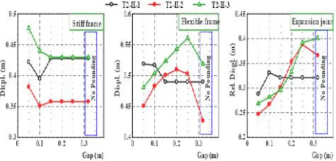
expansion joint and the adjacent bridge segments displacement determine the effect of poundings and restrainers.
Based on the bridge models, the peak responses values of stiff and flexible frame segments displacement and its relative response, Figure 5 for different gape size show that the pounding reduces the segment displacement response when vibrating near the characteristic period of the ground motion and increase the adjacent segment response, Moreover, the relative displacement at expansion joint is driven by the flexible segment response, this effect is more significant with highly out-of-phase frame segments. The displacement response of the segment which has a longer natural period dominates over the displacement response of the segment with a shorter natural period, making the displacement closer to that of the segment with a longer natural period. The displacement time histories of the analyzed superstructure segment for gap 0.1 m (Case II) together with the response when no pounding (Case I) occurs are presented; a positive relative displacement of the expansion joint corresponds to an opening of the joint gap (outward) while a negative relative displacement corresponds to a closing (inward), the results indicate that pounding can significantly alter the behavior of the structure
depending on gap size, frequency ratio and input earthquake wave. Seismic pounding, generates high magnitude and short duration acceleration pulses that can cause structural damage
4.2. Restrainers System for Mitigation of Pounding It is well known that under an extreme excitation, the unseating prevention devices are effective to maintain the integrity of a total bridge system. It prevents an excessive relative displacement between decks or between a deck and substructure and even prevent drop of a deck that dislodges from its support. Variety of unseating prevention devices such as cable restrainers, a connection of adjacent decks and a connection of a deck to a substructure have been used worldwide. Restrainers that connect deck to deck, configuration I perform effectively to minimize the possibility of deck unseating and reduce the pounding forces at the expansion joint for bridge with conventional bearings, where a deck with movable bearing
is connected to a deck on the other side of expansion joint with fixed bearing.
4.3. Shock Absorber for Mitigation of Impact Effects Since poundings between adjacent decks are unavoidable in an isolated bridge, this effect has to be carefully included in design. Poundings results in a transfer of large lateral force from a deck to the other, no matter how the damage of a deck as a direct result of pounding is localized and limited, this results in damage in piers and bearings in the other deck. Consequently it is effective to provide a shock absorber between adjacent decks and at the restrainers ends for the mitigation of pounding effect. The analysis results indicate that reaction forces at the piers bases and pounding forces exerted on the superstructure can be satisfactorily reduced by applying simple method of placing rubber shock absorber between bridge segments or at the restrainers’ ends as potential practical mitigation measures against impact due to poundings and stretching of the restrainers, by that way, the sudden changes of the stiffness can be smoothed
and therefore prevent, to some extent, the acceleration peaks due to impacts. The effects of a natural rubber shock absorber on isolated bridge model response are investigated for the studied cases.
Figure 7 compares response of the bridge model with and without the shock absorbers. In the bridge without the shock absorbers, pounding occurred once resulting in a large impact force; this caused pulse acceleration with high magnitude spikes at the end of the decks. On the other hand, in the bridge with the shock absorbers, the peak pounding force is significantly decreased resulting in the decrease of deck acceleration. Installation of the shock absorbing device significantly reduces the force between the decks generated at expansion joint due to impact and stretching of cable restrainers; hence reduce the acceleration response spikes. When the expansion joint undergoes an increasing relative movement in the positive direction, the rubber pad first deforms under compression action providing resistance to the motion, when the separation relative movement reaches the cable restrainers slack, the restrainers begin to resist further opening of the joint gap. This resistance builds up nonlinearly with joint separation with smooth stiffness change. The interaction between the adjacent segments occurs by both pounding and engagement of the cable restrainers. The installation of a shock absorber could reduce the required cable restrainers’ force; hence more economical design.
CONCLUSIONS
element models for nonlinear seismic pounding analysis are built, and the influence of different parameters on the seismic pounding responses of the highway bridges is analyzed, which include the effects of frequency ratio, gap size, restrainers’ configuration and slack and input ground motion characteristics. The simulations results indicate that the effectiveness of seismic isolation could be significantly affected from potential pounding and unseating prevention measures due to the interaction between adjacent bridge segments occurred by both impacts and the engagement of the cable restrainers that tie together adjacent segments. Seismic pounding, generates high magnitude and short duration acceleration pulses significantly higher than what is typically assumed in design that can result in severe impact forces that damage structural members like the deck or pier. Furthermore, seismic pounding can amplify the global response of the participating structural systems. The influence of pounding on the structural behavior is significant in the longitudinal direction of the bridge and depends much on the gap size between superstructure segments relative to the separation displacement of the model without pounding and input excitation characteristics. The smallest structural response can be obtained for very small gap sizes and for gap sizes large enough to avoid collisions. However, the application of both intervals is usually an undesirable solution. The pounding of adjacent frames will transfer the seismic demand from one frame to the next, which can be detrimental to the stand alone capacity of the frame receiving the additional seismic demand, sothat in situations of potential pounding, neglecting its possible effects leads to the unseating prevention devices are effective to maintain the integrity of a total bridge system, it prevents an excessive relative displacement between decks and even prevent drop of a deck that dislodges from its support. Configuration I of restrainers connecting deck to deck is not effective for unseating prevention for isolated bridges but it could secure falling prevention. However, restrainers through pier (configuration II) and through hinge with shear key (configuration III) could control the expansion joint opening deformation and secure the unseating of the bridge decks on the expense of the increase of shear and moment seismic demand of the supporting pier at the expansion joint, which should be carefully redesign. Restrainers were capable of reducing relative displacements through expansion joint but unseating prevention capability depends on the restrainers’ configuration. Further analysis indicates that reaction forces at the piers bases and pounding forces exerted on the superstructure can be satisfactorily reduced by applying simple method of placing rubber shock absorber between bridge segments or at the restrainers’ ends. The sudden changes of the stiffness during poundings can be smoothed through using natural rubber shock absorber installed at deck ends and/or restrainers end, and therefore prevent, to some extent, the acceleration peaks
due to impacts. Installation of the shock absorbing device significantly reduces the force between the decks generated at expansion joint due to impact and stretching of cable restrainers. The rubber shock absorbing device with half gap/slack size provides economical and effective design that could reduce the impact force and acceleration responses.
REFERENCES
1 Abdel Raheem S. E. (2009). Pounding Mitigation anUnseating Prevention at Expansion Joint of IsolateMulti-Span Bridges. Engineering Structures, 31: 10, 2345-2356.
2 Abdel Raheem, S.E. (2004). Evaluation and prevention of seismic pounding between adjacent building structures.3rd Egyptian Conference on Earthquake Engineering -EGYQUAKE 3, Cairo, Egypt, 6-8 December 2004,253-266.
3.Abdel Raheem, S.E. (2006). Seismic pounding betweenadjacent building structures. Electronic Journal ofStructural Engineering - EJSE, The University of Melbourne, 6, 66 -74.
4.Anagnostopoulos, S.A., and Karamaneas, C.E. (2008).Use of collision shear walls to minimize seismic separationand to protect adjacent buildings from collapse due
to earthquake-induced pounding. Earthquake Engineering &Structural Dynamics, 37: 12, 1371-88. 5.Kazuhiko Kawashima, Kenji Kosa, Yoshikazu Takahash Mitsuyoshi Akiyama, Tsutomu Nishioka, GakuhoWatanabe, Hirohisa Koga, and Hiroshi Matsuzaki. (2011). Damage of Bridges due to the 2011 Great East JapanEarthquake. Proceeding of 43rd Joint Meeting, US-Japan Panel on Wind and Seismic Effects, UJNR, TsukubaScience City, Japan.
6.Moehle, J.P. (1995). Northridge earthquake of January 17, 1994: Reconnaissance report. Volume 1– Highwaybridges and traffic management. Earthquake Spectra,11 (C), 287–372.
7.Committee of Earthquake Engineering, The 1995 Hyogoken-Nanbu Earthquake, Investigation into Damage toCivilEngineering Structures, Japan Society of Civil Engineers, 1996.8.Uzarski J, Arnold C, editors. Chi– Chi, Taiwan, earthquake of September 21, 1999 reconnaissance report.
CA: Earthquake Engineering Research Institute; 2001. 9. Antony G. Gillies, Donald L. Anderson, Denis Mitchell, Rene Tinawi, Murat Saatcioglu, N. John Gardner and Ahmed Ghoborah. The August 17, 1999, Kocaeli (Turkey) earthquake — lifelines and preparedness, Can. J. Civ. Eng. 28: 881–890 (2001). 12 10. Jankowski, R., Wilde, K., and Fujino, Y. (2000). Reduction of pounding effects in elevated bridges during earthquakes. Earthquake Engineering and Structural Dynamics, 29, 195-212.
response of multiple-frame bridges. ASCE Journal of Structural Engineering, 128: 7, 860-869.
12. Takeno, S., Ohno, H., and Izuno, K. (2004). Velocity-based design of seismic unseating prevention cable and shock absorber for bridges. JSCE Structural Engineering and EarthquakeEngineering, 21: 2, 175-188.
13. Zhu, P., Abe, M., and Fujino, Y. (2004). Evaluationof pounding countermeasures and serviceability of elevated bridges during seismic excitation using 3D modeling. Earthquake Engineering and Structural Dynamics, 33, 591-609.
14. Ruangrassamee, A., and Kawashima, K. (2001). Relative displacement response spectra with pounding effect. Earthquake Engineering and Structural Dynamics, 30, 1511–1538.
15. Abdel Raheem, S.E., and Hayashikawa, T. (2003). Parametric study on steel tower seismic response ofcable-stayed bridges under great earthquake groundmotion. JSCE Structural Engineering and EarthquakeEngineering, 20: 1, 25-41. 16. Kawashima, K., and Shoji, G. (2000). Effect of restrainers to mitigate pounding between adjacent decks subjected to a strong ground motion. 12th World Conference on Earthquake Engineering-12WCEE, Auckland, New Zealand, 31 January - 4 February 2000, Paper No. 1435.
17. Abdel Raheem, S.E., and Hayashikawa, T. (2008). Control strategy for seismic pounding mitigation of bridge structures.” International Association for Bridge and Structural Engineering–IABSE, Information and Communication Technology (ICT) for Bridges, Buildings and Construction Practice, Helsinki, Finland, June 4-6, 2008, Paper ID B35.
18. bdel Raheem, S.E., and Hayashikawa, T. (2008). Innovative Control Strategy for Seismic PoundingMitigation of Bridge Structures. 14th World Conference on Earthquake Engineering,Beijing, China, October 12-17, 2008, Paper No. 05-02-0107.