CODITEL
Telephony Systems Trainer
1 Unit: CODITEL. Telephony Systems Trainer
PROCESS DIAGRAM AND ELEMENTS ALLOCATION
Computer ControlSoftware
3
Teaching Technique
used
Computer (not included in the supply)
Cables and Accessories Manuals
Always included in the supply:
www.edibon.com
Products Products range
Units
3.-Communications
Page 1
Worlddidac Quality Charter Certificate
Worlddidac Member ISO:9001-2000 Certificate
of Approval. Reg. No. E204034 European Union Certificate ECO-Management and Audit Scheme Certificates ISO 14001: 2004 and
(environmental management) Worlddidac Member
Technical Teaching Equipment
2
4
DESCRIPTION
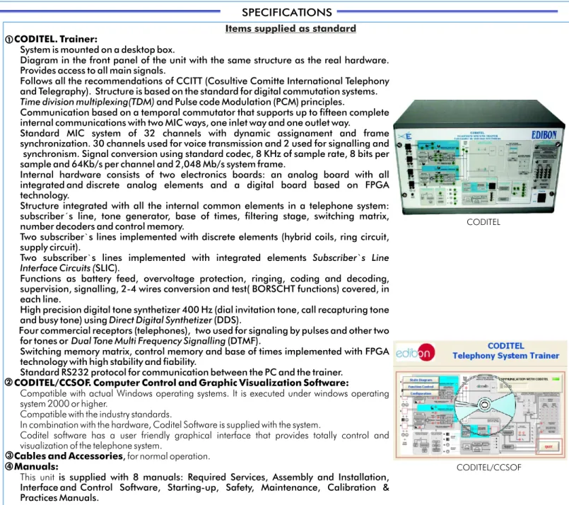
CODITEL. Trainer:
System is mounted on a desktop box.
Diagram in the front panel of the unit with the same structure as the real hardware. Provides access to all main signals.
Follows all the recommendations of CCITT (Cosultive Comitte International Telephony and Telegraphy). Structure is based on the standard for digital commutation systems.
Time division multiplexing(TDM) and Pulse code Modulation (PCM) principles.
Communication based on a temporal commutator that supports up to fifteen complete internal communications with two MIC ways, one inlet way and one outlet way.
Standard MIC system of 32 channels with dynamic assignament and frame synchronization. 30 channels used for voice transmission and 2 used for signalling and
synchronism. Signal conversion using standard codec, 8 KHz of sample rate, 8 bits per sample and 64Kb/s per channel and 2,048 Mb/s system frame.
Internal hardware consists of two electronics boards: an analog board with all integrated and discrete analog elements and a digital board based on FPGA technology.
Structure integrated with all the internal common elements in a telephone system: subscriber´s line, tone generator, base of times, filtering stage, switching matrix, number decoders and control memory.
Two subscriber`s lines implemented with discrete elements (hybrid coils, ring circuit, supply circuit).
Two subscriber`s lines implemented with integrated elements Subscriber`s Line Interface Circuits (SLIC).
Functions as battery feed, overvoltage protection, ringing, coding and decoding, supervision, signalling, 2-4 wires conversion and test( BORSCHT functions) covered, in each line.
High precision digital tone synthetizer 400 Hz (dial invitation tone, call recapturing tone and busy tone) using Direct Digital Synthetizer (DDS).
Four commercial receptors (telephones), two used for signaling by pulses and other two for tones or Dual Tone Multi Frequency Signalling (DTMF).
Switching memory matrix, control memory and base of times implemented with FPGA technology with high stability and fiability.
Standard RS232 protocol for communication between the PC and the trainer.
CODITEL/CCSOF. Computer Control and Graphic Visualization Software:
Compatible with actual Windows operating systems. It is executed under windows operating system 2000 or higher.
Compatible with the industry standards.
In combination with the hardware, Coditel Software is supplied with the system.
Coditel software has a user friendly graphical interface that provides totally control and visualization of the telephone system.
Cables and Accessories, for normal operation. Manuals:
This unit is supplied with 8 manuals: Required Services, Assembly and Installation, Interface and Control Software, Starting-up, Safety, Maintenance, Calibration & Practices Manuals.
1
SPECIFICATIONS
*
References 1 to 4: CODITEL + CODITEL/CCSOF + Cables and Accessories + Manuals are included in the minimumsupply, enabling a normal operation. 2
3 4
Page 2 www.edibon.com
The term digital commutation is directly related with the communication (or connection) networks.
Formerly, any communication established through a switch station occupied a physical path separate from the rest, by means of a matrix of cross points, mechanically implemented (spatial commutation).
Thanks to the development of the digital technology, the electromechanical networks have been replaced by electronic circuits, based on the digital (or temporal) commutation.
The CODITEL trainer is based on a digital or temporal commutator enabling the study ofemission in any order on the channels of an outlet multiplex. The samples that are shown in a certain order, on channels of an inlet multiplex.
CODITEL is a digital circuit commutation unit for didactic purposes. Its structure is like a temporal commutator structure with two MIC ways, one inlet way and one outlet way. Basically, it follows the recommendation of the CCITT and of Telephony.
This trainer consist of the following parts: interfaces (connection with the outer world), internals, digital connection network and control system: Interfaces:
It consists of four user line circuits, two lines for tone terminals (multifrequency) and two lines for pulse terminals (decadic), made in different ways: The multifrequency circuits are hybrid integrated circuits carrying out all the basic functions of a line circuit.
The decadic circuits, where all their structure is mounted discrete components. The four line circuits are compatible with commercial user apparatus. Internals:
The trainer has four number receiver, two of them are pulse receivers (decadic) and the other are tone receivers (DTMF), assigned to a specific line. It has a time base that supplies the appropriate temporization for the whole system and a digital tone generator.
Digital connection network:
The connection network is a temporal commutation matrix, made with memories. Its architecture is like the one with a sequential writing and asynchronous reading commutator.
Control system:
The control is carried out by a program stored in the computer (PC), and it is executed under the windows operating system 2000 or higher. The communication between the computer (PC) the interface through serial RS232 protocol.
Items supplied as standard
CODITEL/CCSOF CODITEL
EDIBON Computer Control System
Main screen
Software Main Screens
Page 3 www.edibon.com
Continue... It shows the state of communication between the unit and the PC. From this screen we can go to the 3 main windows of the software.
Software Main Screens
(continuation)Page 4 www.edibon.com
In this window is shown the following information:
-State Diagram of each line. Each line has its own state diagram . You can select the diagram you want to see by clicking in the State Diagram Line menu in the upper right side of the window.
-States. The current state of each line are shown.
-Status. It represents the state of the phones. It also indicates the assigned number or numbers of each line.
This subwindow shows the number of calls, charge, duration, line Tx, line Rx.
Continue...
Page 5 www.edibon.com
EDIBON Computer Control System
The functions that can be activated are the following:
-F0. Activates the ring of a line. -F2. Desactivates the ring of a line. -F1. Shows the state of a telephone. -F7. Activates the tone of a line. -F3. Desactivates the tone of a line. -F4.Assigns to a line a slot or
channel.
-F5.Establishes the switching between a emitter and receiver.
In this window, you can assign several numbers to a line. It is also possible to configure whether a telephone can send or receive calls and set tax of each line.
Function Control window
Lines Configuration window
Minimum configuration for normal operation includes: Unit: CODITEL.
CODITEL/CCSOF. Computer Control and Graphic Visualization Software. Cables and Accessories, for normal operation.
Manuals.
* IMPORTANT: Under CODITEL we always supply all the elements for immediate running as 1, 2, 3 and 4.
Telephony Systems Trainer.
REQUIRED SERVICES
DIMENSIONS & WEIGHTS
Dimensions: 490 x 330 x 310 mm. approx. Weight: 20 Kg. approx.
- Electrical supply: single-phase, 220V./50Hz or 110V./60Hz. - Computer (PC).
ORDER INFORMATION
1 2 3 4
1.-To study the main actions and signals involved in a digital 8.- To study the electric stages when the user makes actions over the
commutation. telephone.
2.-To study the dynamic channel assignment and temporal switching. 9.- To study the signals involved when dialing by pulses.
3.-To study the standards for audio conversion. 10.- To study the signals involved when dialing by tones.
4.-To establish of a communication between some channels step by 11.- To study the tone signal. step.
5.-Visual monitoring of the main states that a line goes through during a call.
6.-To configure lines as only receiver, transmitter, receiver / transmitter.
7.-To test of the conversion from 2 to 4 wires.
Items supplied as standard
ORDER INFORMATION
Some Practical Possibilities of the Unit:
*
Specifications subject to change without previous notice, due to the convenience of improvements of the product.Issue: ED01/08 Date: May/2008
REPRESENTATIVE:
C/ Del Agua, 14. Polígono San José de Valderas. 28918 LEGANES. (Madrid). SPAIN. Phone: 34-91-6199363 FAX: 34-91-6198647
E-mail: [email protected] WEB site: www.edibon.com
Page 6