© 2019, IRJET | Impact Factor value: 7.211 | ISO 9001:2008 Certified Journal
| Page 2269
DESIGN OF EARTHQUAKE RESISTANT STRUCTURE OF MULTI-STORY RCC
BUILDING
AKASH KUMAR
1, ER. KUNDAN KULBHUSHAN
21
M.TECH Structural Engineering, Maharishi University of Information Technology, LUCKNOW UP, India
2Head of Department of Civil Engineering, Maharishi University of Information Technology, LUCKNOW UP,
India, 226013.
---***---
Abstract: I am presently working in G+21 story earthquake resistant multi-story reinforcement cement concrete building. The building design criteria are different in different earthquake zone in India. But I have taken earthquake zone III (LUCKNOW)
and it comes under moderate risk area.The building is design by ETABS software. These projects are classifying the seismic
analysis with lateral forces by the effect of earthquake. Design & construction of an earthquake resistant structure have more important to all in the world. A Designer are design the building frames at foundation level to top also design the intermediate floors. In building have different components beams, columns, floors and walls. Design of earthquake resistant structures given proper bonding, spacing and anchorage length at joints of beams and near column given closed spacing and large bonding anchorage bars or bent up bars. These are design high rise building according to software. Project is to learn relevant Indian standard codes are used for design of various building elements such as beams, columns, slabs, foundation, and stair. Analysis of all buildings story components with seismic action in the limit of Indian standard code provision. Taking some Indian standard code to design the earthquake resistant building structure in the form of seismic force, earthquake resistance and ductile detailing of seismic force of RC structure use of code IS:456, IS:875, IS:1893, IS:4326-1993 and IS:13920-1993. But design of normal RCC structure due to code provision IS: 456-2000.
To study the all common parts of building at the story level to high level, also consider the gravity load, dead load, wind load or seismic forces, and drift forces. Currents more use full design of high rise building by the structural design software. These are software design of building frames in beams, columns, slabs of structures and also design the bending moments, shear force, stiffness, rotations, torsion and deflection in frames and its other parts of the structures. We have to consider better design to make a high rise building. In India show that 54% of the land living is unsafe to earthquake. Earthquakes are very serious problems since they are evaluate that this phenomena by some techniques as base isolation, dampers, wire and other methods. Also works to better design to resist the seismic waves. We have to take better high quality materials and given better factor of safety in design process. In this study the aim is to analyze the response of a high-rise structure to lateral loads using static and dynamic seismic loads and static wind loads. This analysis procedure is based on IS codes for Design analysis of Structures. The results of analysis are used to verify the structure fitness for use, finally the comparison of all lateral stability checks has been carried for zone 3. Design and detailing of one critical element has been shown in this study.
Key words: ETABS, earthquake zone, seismic force, drift force and lateral load et
1.1 INTRODUCTION
1.1 Introduction
© 2019, IRJET | Impact Factor value: 7.211 | ISO 9001:2008 Certified Journal
| Page 2270
type of structural model selected. We can design of G+21 RCC building in the LUCKNOW So I taken proper location of sites which are stands the G+21 story building. In the site taking sample to works all test. Soils are silt, sand and clay proportion so taking better bearing capacity. The building frames are stands on mat foundation. The mat foundation is taking more loads bearing capacity as compare to isolated footing, strip footing and combined footing. Mat foundation is very simple to work as compare to pile foundation and it is very less expensive to pile foundation.The design of reinforced concrete multi storey buildings consist of beams, columns, floor slabs, walls, foundation and other special features of RC multi storey buildings continuously placed to form a rigid monolithic frame system. A building may have a regular (symmetrical) or irregular (unsymmetrical) geometric shapes. A regular shape of building can take mores strong earthquake intensity. A building is subjected to gravity loads such as dead loads and live loads and lateral loads to the effects of wind and earthquake loads. These loads are required to transfer safety to the soil below interconnected structural systems. The connection between beam and column or column and wall or beam and wall or bracing member may be simple or moments resistant based. In tall buildings the biggest challenge comes from satisfying the serviceability limit states, constructability, durability as well as economy. This system is satisfying to all this requirements.
1.2 Gravity loads system
i. Slab supported on live loads
ii. Column supported on slab loads
iii. Also column supported on beams loads
iv. Beams supported on column loads
v. Slab supported on beams
vi. Beams supported on walls loads
1.3 Lateral loads system
i. Shear walls
ii. Moments resisting frames
iii. Braced frames
iv. Tabular system
1.4 Lateral stability checks
To be carried out equivalent static and dynamic analysis of Response spectrum and time history analysis for the proposed building. Lateral stability checks for both the methods are carried out.
i. Base shear
ii. Storey drift
iii. Storey displacements
iv. Storey stiffness
v. Weak storey
vi. Soft storey
vii. Modes
viii. Redundancy
The tall building stiffness elements are required to control the lateral drift from the serviceability consideration. The stiffness are provides in the walls and diagonal panel members and member of stiffness reflect the degree of cracking and inelastic action. Also stiffness of elements are classify on the basis of computer software. Some of the structural engineering software
includes AUTO CADD, STAAD-PRO, ETABS, SAP2000, and ANSYS is a subset of SAP2000 for use in building only. Etabs is
essential program for analysis and design of framed building including flexure walls.It does not design slab and foundation so
© 2019, IRJET | Impact Factor value: 7.211 | ISO 9001:2008 Certified Journal
| Page 2271
force (Newton's second law of motion) can be neglected and the analysis can be simplified to static analysis. A structural engineer can exercise the some degree of control of magnitude, distribution of mass, stiffness, relative strength of member and ductility of the design structures. An earthquake resistant designer must provide both sufficient strength as well as ductility. Ductility can signify the inelastic deformation prior to collapse structures. Torsion analysis of the structure can be defined by eccentricity of the floor and also using the relative stiffness of the frames. A response spectrum analysis to compute the member forces in the multi storey buildings frame. Therefore, structural dynamics is a structural analysis that covers the behavior of structures that are loaded dynamically (with high acceleration). Dynamic loads include people, wind, waves, traffic, earthquakes and explosions. Any structure can withstand dynamic loads. Dynamic analysis can be used to find dynamic displacement, time history and modal analysis.A structural system may be classified as follow.
a. Load bearing wall system
b. Moment resisting frame system
c. Flexural wall
d. Dual frame system
e. Tube system
Masonry walls provide support for all gravity loads as well as resistance to lateral loads. The walls and partition walls supply in plane lateral stiffness and stability to resist winds and earthquake loadings. This system lacks in providing redundancy for the vertical and lateral support. That is if wall fails. In this used the IS: 4326-1993. In which members and joint are capable of resisting vertical and lateral load primarily by flexural. The beam column joint is the most crucial component. The moment distribution among beam and column take place through joint. If a beam column joint fails, the whole structure system will fail. In a moment resistant frame, relative stiffness of girder and column is very important. A frame may be designed as having weak column strong girder proportion or strong column weak girder proportions. It is a reinforced concrete wall designed to resist lateral forces parallel to the plane of the wall and detailed to provide ductility. A column is supposed to deflect in shear mode where as a wall is expected to deflect in bending mode. There is no clear distinction between a column and a wall except dimensional. This is used to IS: 13920-1993. Flexural walls, that is shear walls or braced frames must resist the total required lateral force in accordance with relative stiffness considering the interaction of the walls and the frames as a single system. This analysis must consider the relative stiffness of the structural and torsion effect in the system. The design of a multi-storey building, there is need to very carefully study architectural drawings and geotechnical report of the site. Various loads likely to act on the building during its life span must be assessed as accurately as possible. There is a need to prepare a report on the design philosophy for multistory building covering all functional, architectural, and structural aspects including the use of various code specifications. Even through, high rise building occupied architectural and construction scene and do play an important for solving excessive land consumption problem and problem of accommodation in overpopulated zone, architectural critics are generally describing high rise as gigantic hazards in urban areas and tools to show off the prestige, power and wealth. Which do create environment oversized if compared to human scale and do cause harmful influence on environment. As everything high rise buildings do have its advantage and disadvantage, but one is sure, high rise buildings are accepted by mass population. It is common for every urban area to have structure and building which are characteristic high rise because they outstand among other building in surrounding. In term of these advanced technology, high rise building were celebrated on the cast iron and steel load bearing structural elements which were designed to form rigid frames. More slender structural elements, larger spans more open floor plans presented steel as material of future. Early advance technology developing and experimental study tried to overcome the problem of massiveness of the concrete structures and its compressive strengths.
© 2019, IRJET | Impact Factor value: 7.211 | ISO 9001:2008 Certified Journal
| Page 2272
1.5 LoadsThe building frames are design by dead loads, live loads or imposed loads and wind loads or earthquake loads.
1.5.1 Dead loads
The dead loads on a frame calculated floor wise and consist of weight of floors, girder, partition walls, false ceiling, parapets, balcony, fixed or permanent equipments and half of column above and below a frames.
1.5.2 Live loads
The magnitude of live load depends upon the type of occupancy of the building. The live loads are given by Indian standard code IS: 875-1987 (parts 2) of minimum specified values.
1.5.3 Wind loads
Wind is essentially a random phenomenon. In the past it was considered sufficient to use the highest wind speed that had been recorded at the metrological station nearest the site. The corresponding wind pressure was applied statically.
1.6 Guideline for earthquake resistant structures
A designer should be attention to ensure the sufficient ductility or to be detailing of reinforcement, bars cut-offs, splicing and joint detailing. The selection of crass section will have adequate strength. Then you can justify a desire possibility so can achieved desire strength.
The structure layout should be simple and regular avoiding offset of beams to column, or offsets of column from floor
to floor. Changes in stiffness should be gradual from floor to floor.
The amount of tensile reinforcement in beam should be restricted and more compression reinforcement should be
provided. The letter should be enclosed by stirrups to prevent it from buckling.
Closed stirrups or spiral should be used to confine the concrete at section of maximum moment to increase the ductility of member.
Shear reinforcement should be adequate to ensure that the strength in shear exceeds the strength in flexure.
Design of building should be based on seismic code IS: 1893 (part-1) 2002 and other this code IS: 13920-1993.
Integral action of soil foundation and superstructure system.
Structure should not have large height & width ratio.
Column and wall should be continuous without offset from the roof to the foundation.
Beams & column should be equal width.
The structure should be ductile as for as possible.
The structure should have uniform floor height.
The structure should be designed on strong column weak beam concept.
Load should be uniformly distributed.
Column & beam should be co-axial.
Beam & column in a reinforced concrete frame should be designed in such a manner that inelasticity is confined to
beam only and the column should remain elastic.
To ensure this sum of moment capacity of the column for the design axial loads at a beam & column joint should be
greater than the moment capacity of the beam along each principle plane.
The structure should have balanced lateral resistant.
Shear wall should be provided for increasing stiffness.
The structure should have low centre of mass relative to the ground.
Avoid ground floor soft storey.
© 2019, IRJET | Impact Factor value: 7.211 | ISO 9001:2008 Certified Journal
| Page 2273
The reversal of stresses in beam & column due to reversal of direction of earthquake force must be taken.
There should be uniform distribution of mass, stiffness & strength.
These should be a greater emphasis on the quality of construction.
The structure should not be large in length nor should they have large plan area.
Beams should be free of offsets
Beam & column connection should be made monolithic.
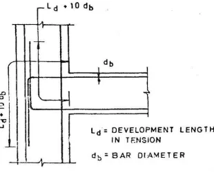
Splices and bar anchorage must be adequate to prevent bond failure.
[image:5.612.170.480.199.456.2]
Fig. 1.1 Anchorage of beam bar in an external joint
1.7 Analysis
Building analysis should be work in the Indian code provision as per IS: 1893-2002. This is design the seismic zone map specify seismic force. G+21 high rise buildings are different types of analysis considered
1.7.1 Equivalent analysis
The high rise building cannot be considered a simple static method. It is a unique method to determine seismic loads. The equivalent static analysis is used to design only for the small structures. In this method only one mode is considered for each direction.
1.7.2 Response spectrum
© 2019, IRJET | Impact Factor value: 7.211 | ISO 9001:2008 Certified Journal
| Page 2274
1.7.3 Time history analysisIt is taken by historical data or values of index for the given by specific periods of time. These are data taken a future or forecasting rate movements. The time history data provides structure response under various loading cases to the specified time function.
1.8 Materials
[image:6.612.163.448.248.324.2]1.8.1 Concrete, Steel and Bricks
Table 1.1 material specific data
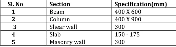
1.8.2 Frame section properties
Table 1.2 section specific data
1.8.3 Loads detailing
Table 1.3 load specific data
Sl. No Property Intensity of load(KN/M) 1 Live load 4.0
2 Floor or slab load 1.5 3 Water proofing 2.0 4 Terrace 1.0
1.9 Design procedure
Step-1 Lumped masses to various floor levels
Whole structures are considered as a single unit system and this unit of a structure system mass is called lumped mass.
Dead load
Floor
Roof
Beam
Column
Sl. No Section Specification(mm)
1 Beam 400 X 600
2 Column 400 X 900
3 Shear wall 300
4 Slab 150 - 175
5 Masonry wall 300
Sl. No Property Specification
1 Grade of concrete M35 & M40
2 Grade of steel HYSD 500
3 Density of brick 20 KN/M^3
4 Density of RCC 25 KN/M^3
© 2019, IRJET | Impact Factor value: 7.211 | ISO 9001:2008 Certified Journal
| Page 2275
Wall
Live load
Floor
Roof
These are dead & live load summation is called as total seismic load.
Total seismic load = Dead load + Live load
Step-2 Load combinations
Wind load and earthquake load are not considered at same time. Only should be considered at a time. 0.9 values for DL considered when stability of structure against over- turning is critical. It can give standard values on partial factor of safety for load also considered for limit state of collapse.
Load combination = 1.5/0.9DL + 1.5EQL/WL
Load combination = 1.2DL + 1.2LL + 1.2EQL/WL
Load combination = 1.5DL + 1.5LL
Step-3 Calculation of wind loads
Wind is essentially a random phenomenon. The wind load can design by IS: 875-1987(part-3). Also it is taken past records near the location. It is the statistical and probabilistic approach to the evaluation of wind loads. The design of wind speed Vz at a given height.
The design wind speed (Vz) = Vb × k1 × k2 × k3
The variation of wind speed with height is given
Vz ÷ Vo = (Z ÷ Zo)^α
Where,
Vb = basic wind speed in m/s at 10m height
k1 = probability or risk factor
k2 = terrain and structure size factor
k3 = local topography factor
Vz = wind velocity at height Z above ground
Vo = basic wind velocity at the reference height Zo
α = an exponent depends upon terrain roughness
The design of wind pressure Pz in N/m^2 at any height above the mean ground level is given.
© 2019, IRJET | Impact Factor value: 7.211 | ISO 9001:2008 Certified Journal
| Page 2276
Step-4 Fundamental natural period (Ta)The fundamental period of moments resistant reinforced concrete building with shear wall may be determine by empirical formula.
Braced building
Ta = 0.09H/D½
Where,
D = depth of building in meter in the direction of the earthquake force H = height of building in meter above ground level
Ta = fundamental period of the building in second
Un-braced building
Ta = 0.075H^0.75
Step-5 Design seismic base shear (Vb)
The base shear (Vb) = Ah × W × D
Ah = (Z/2) (I/R) (Sa/g)
Where,
Ah = design horizontal acceleration spectrum values
Z = zone factor
R = response reduction factor
Sa = spectral acceleration depending on the period of vibration
I = importance factor
Sa/g = average response acceleration
Step-6 Vertical distribution of base shear
Qi = Vb×[[(Wi)×(Hi)^½]÷[Σi^n(Wi)×(Hi)^½]
Where,
Qi = design lateral force at floor I (all storey find different)
Wi = seismic wt. of floor i
Hi = height of floor from base in meter
© 2019, IRJET | Impact Factor value: 7.211 | ISO 9001:2008 Certified Journal
| Page 2277
2. METHODOLOGYAt present works G+23 reinforce cement concrete earthquake resistant building is consider for different storey height & different seismic zone. The structure model & analysis by using ETABS software of computer aided design.
2.1 Flow diagram
RCC Frame G+23 Structure model
Draw the plan of Building by AUTO CDD software
Also draw the column
plan of building by AUTO CADD software and import the file into e-tabs application
Draw the grid system & Stand the G+23 storey RCC frame and analyzing the beam, column, walls, and slabs by using e-tabs application.
Analysis the Gravity (DL+LL) & Seismic load
zone3 Structure analysis using e-tabs
After analysis Run the structure and then design so, find final
© 2019, IRJET | Impact Factor value: 7.211 | ISO 9001:2008 Certified Journal
| Page 2278
2.2 Preparation of DrawingsThe structure drawings are needs to be prepared for multi-storey building by the helps of computer aided based design. The major requirements of multi-storey building are design many of the private and government departments. The G+23 multi-storey RCC building frame can be design by E-tabs application and foundation works through the using STAAD-PRO application.
Foundation
Foundation plan
To draw the plan of foundation by help of AUTO CADD software.
Then specify the load of structure then design the raft & pile foundation with the help of STAAD-PRO software and
used concrete grade.
The foundation schedule showing the section and reinforcement details.
Column
To specify the dimension of column and grade of concrete.
In E-tabs software to be design the column schedule for all columns from foundation to showing the cross-section,
reinforcement detailing, overlapping etc. it may used to some column extend up to the top of roof water tank.
Beam
To specify the dimension of beam and grade of concrete.
Then analysis of beam by using the software E-tabs.
The beam schedule showing the plinth level reinforcement details, floor level reinforcement details in multi-storey
building.
Beam schedule at terrace level
Shear wall
To the specify thickness of the shear wall and grade of concrete.
The analysis of shear wall by using E-tabs software after run and design.
Shear wall scheduling the cross-section, reinforcement detailing, and overlapping etc.
Shear wall is using around the periphery of staircase, lift and water tank schedule.
Slab
Slab is divides in panel section.
To the specify thickness of the slab and grade of concrete to used.
Framing plan and slab schedule at plinth level, typical floor level and terrace level.
Slab scheduling showing the reinforcement and cross-section.
3. CONCLUSION
© 2019, IRJET | Impact Factor value: 7.211 | ISO 9001:2008 Certified Journal
| Page 2279
earthquake building design more focus on building lateral forces and also consider the good flexibility joints between the beams and column. I have taken suitable data by analysis of Indian standard code provision and also study the earthquake zone 3 in LUCKNOW.
All analysis before I have analyzed the joints of beams and column taking very carefully and also take more FOS then
my building will be safe zone.
In the earthquake condition beams & column width taking equal size so bonding between them very economically.
Also my building G+21 in plan of beam & column joints by linear not offsets occurs because the offset can failure phenomenon.
I can design proper and suitable data analysis so my building is economically very good.
Also cast of building is reduces.
REFERENCES
1. IS:456-2000
2. IS:875-1987
Part 1 for dead load Part 2 for live load Part 3 for wind load
3. IS: 1893 (part1):2002, Indian standard criteria for earthquake resistant design of structure (5th revision).
4. IS: 4326, 1993 Indian standard code for practice for earthquake resistant design & construction of building (2nd
revision).
5. Design of a six storey building Dr. H. J. shah department of applied mechanics MS university of Baroda VADODARA and
Dr. S. K. Jain department of civil engineering IIT Kanpur.
6. Ashok K. Jain professor and head of department of civil engineering IIT ROORKEE.
7. Design of residential building guide.