Fractional Order PID Controller Design for Speed
Control DC Motor based on Artificial Bee Colony
Optimization
Ibrahim K. Mohammed
College of Electronics Engineering Systems and Control Eng. Dept.
Ninevah University/ Mosul/ Iraq
Abdulla I. Abdulla
College of Electronics Engineering Systems and Control Eng. Dept.
Ninevah University/ Mosul/ Iraq
ABSTRACT
A proportional–integral–derivative (PID) controller is very popular in applications that require an easy and comprehensive control. In this project, the application of soft-computing algorithm design based on Artificial Bee Colony (ABC) optimization technique is integrated with Fractional order PID controller (FOPID) . It is an advancement of conventional PID controller in which the derivative and integral order are fractional rather than integer. Apart from the usual tuning parameters of PID, it has two more parameters λ (integer order) and μ (derivative order) which are infractions. This increases the flexibility and robustness of the system and gives a better performance .The aim of this work is to design a speed controller of a DC motor by selection of proper FOPID parameters using bio-inspired optimization technique of Artificial Bee Colony Optimization (ABC). The application of ABC to the FOPID controller imparts it the ability of tuning itself automatically in an on-line process while the application of optimization algorithm to the PID controller makes it to give an optimum output by searching for the best set of solutions for the PID parameters.
Keywords
Fractional Order PID Controller (FOPID), Artificial Bee Colony Optimization; Tuning Algorithm
1.
INTRODUCTION
During the past decades there is a considerable interest in designing high efficiency motor drives due to widely used of drives in industrial applications such as rolling mills, paper mills, mine winders, hoists, machine tools, traction, printing presses, textile mills, excavators and cranes. These applications demand adjustable speed, good speed regulations, frequent starting, braking and reversing. To match these demanded industrial criteria a robust and high performance motor control system should be designed. Although so many research works have been done in field of design of motor control system, however, the development and further improvement in performance of the motor drives is still a target of many engineers and research centers.
Direct Current (DC) motor is among various electric motors that can provide excellent control of speed for acceleration and deceleration. The DC motors have been popular in drive application field as the power supply of the system is directly fed to motor which allows for a precision in current control. In addition, their high start torque characteristic and high response performance enabled them in speed and torque control applications. Moreover, these motors are also able to provide starting and torques for loads up to 400% than rate [1][2].
Simulated Annealing (SA) and frequency domain design (FDD) method. The time response of both of controllers is presented on the basis of unit step response. The performance of PID/FOPID controller is compared based on control criteria parameters.
Classical PID Fractional order PID controllers are proposed by [12] for DC motor based on GA optimization method. The time response of the controllers is demonstrated and their performance is compared to evaluate the proposed control system. Simulation results showed that shortest rise time achieved based on FOPID controller is 0.3 s. Anguluri et. al introduced DC motor control system using PID and FOPID controller based on artificial bee colony algorithm (ABC) optimization method. Simulation results of the control system are demonstrated and then compared. However, effect of friction coefficient of motor is not taken into consideration in the modeling of their proposed system. Furthermore, the performance of the control system showed overshoot and not short enough rise time. Moreover, control input of the system is not calculated.
In this paper, a good performance and robust speed control system for a DC motor using PID and FOPID controller based on high efficient ABC optimization method is introduced. The rest of paper is organized as follows. Section II presents mathematical modeling dynamics of DC motor drive. Theory of fractional order systems is introduced in Section III. Section IV deals with Artificial Bee Colony optimization algorithm. A detailed explanation of ABC-based PIP/FOPID control system design is stated in Section V. Finally, simulation design of speed control system and results are presented in section VI followed by conclusions and future work details in Section VII.
2.
SYSTEM PLANT MODELING
All Consider a DC motor with a single rigid rectangular coil constituted by a single wire where a current
i
flows, suitably located in a uniform exogenous magnetic field (B), then the torque (T) exerted at the center of the coil is given by:ildB
T
(1) Wherel
is the length of the wire perpendicular to the magnetic fieldB
(m),d
is the length of an edge of coil (m). The flux
flowing through the rotor of DC motor is proportional to magnetic fieldB
,
the above torque expression can be rewritten as follows:i
K
T
(2) Where
K
ld
/
A
. In this work, the magnetic fieldB
is assumed constant, hence
is constant, and then the motor torque can be written as:i
K
T
T (3)Where
K
T
K
is a motor torque constant. Based on Farady’s law, the back electromotive force (EMF) induced in the wire is given by:,
dt
d
E
a c
(4)
where
c is the flux flowing in the internal surface of a closed wire (Wb
). Similarly to the case studied in (2) and (3), the back EMF can be written as follows:w
K
E
a
a (5)where
K
a is the motor electromotive factor constant andw
is the angular velocity of the motor (m/s)In SI units, the motor torque and back emf constants are equal, that is,
K
T
K
a,
therefore, the constant K is used to represent both the constants i.eK
K
a
K
T.
The equation of the system dynamic is derived based on second Newton’s law and is given by:
Ki
Bw
dt
dw
J
(6)While the electric equation of the system is formulated based on Kirchhoff’s voltage law as follows:
,
Kw
E
Ri
dt
di
L
a
(7)where
J
is motor inertia(
kgm
2)
,B
is the motor viscous friction coefficient(
Nms
)
,w
is the angular velocity of the motor(
rad
/
s
)
andL
,R
andE
a is the inductance (H), resistance (
) and voltage (V) of the coil respectively. Applying the Laplace transform, the above system dynamic equations (6) and (7) can be expressed in s-domain as follows:)
(
)
(
)
(
Js
B
w
s
KI
s
(8)Fig 1: Block diagram of a current controlled DC motor.
)
(
)
(
)
(
)
(
Ls
R
I
s
E
as
Kw
s
(9)In this paper, the block diagram of the armature current controlled DC motor is shown in Figure 1. Based on (8) and (9), the open loop transfer function with the motor voltage
)
(
s
E
a as the system input and the angular velocityw
(
s
)
of the motor as the system output is as follows [13]:2
)
)(
(
)
(
)
(
K
B
Js
Ls
R
K
s
E
s
w
a
(10)
Applying the realistic parameters values of DC motor system, which are listed in Table 1, the final transfer function of DC motor approximately becomes
000559
.
0
01
.
0
005
.
0
023
.
0
)
(
)
(
2
s
s
s
E
s
w
a
(13) Table 1. Typical parameters values for DC motor
Parameter Symbol Typical Value
Motor inertia
J
2
.
01
.
0
kg
m
Coil inductance
L
0
.
5
H
Coil resistanceR
1
Motor constantK
0
.
023
Nm
/
A
Friction
B
0
.
00003
Nms
3.
THEORY OF FRICTIONAL ORDER
SYSTEM
3.1
Fractional Order Calculus
Please Fractional order calculus is an area of calculus which generalizes the derivative or integral of a function to non-integer (fractional) order. Fractional calculus evaluates (
n n
dt
y
d
),
n
-fold integrals where n is fractional, irrational or complex [3]. This mathematical operation allow to establish a more concise and accurate model than the classical integer-order method. Moreover, the Fractional integer-order calculus can also provide a good tool for describing dynamic process for control systems.Fractional order calculus is a generalization of differentiation and integration to non-integer order fundamental operator which is denoted by
aD
t wherea
andt
are the operation limits and
(
)
is the order of the operation. The formula of continuous differ-integral operatoraD
t is defined as follows [3]:
0
)
(
0
1
0
t a t td
dt
d
aD
(12)There are two commonly used definitions for general fractional differ-integral
aD
t which are used for realization of control problem algorithm: Grunwald – Letnikov (GL) definition
)
(
)
1
(
)
(
] [ 0 0lim
f
t
jh
j
h
t
f
aD
h a t j j ht
Where
[.]
denotes the integer part of operator Riemann-Liouville definition
d
t
f
dt
d
t
f
aD
t a n n nt
1)
(
)
(
)
1
(
1
)
(
(14)The condition for above equation is
n
1
n
,
(.)
is called Gamma function.The definition of Gamma function is given by
dz
e
z
x
x z
0 1)
(
(15)Laplace transform of differ-integral operator
aD
ta is given by expected form
dt
t
f
D
e
t
f
D
L
[
t(
)]
st t(
)
0 0 0
(16))
(
)
1
(
)
(
)]
(
[
0 11
0
0
D
f
t
s
F
s
s
D
f
t
L
t m [image:3.595.62.274.87.227.2]n m j t
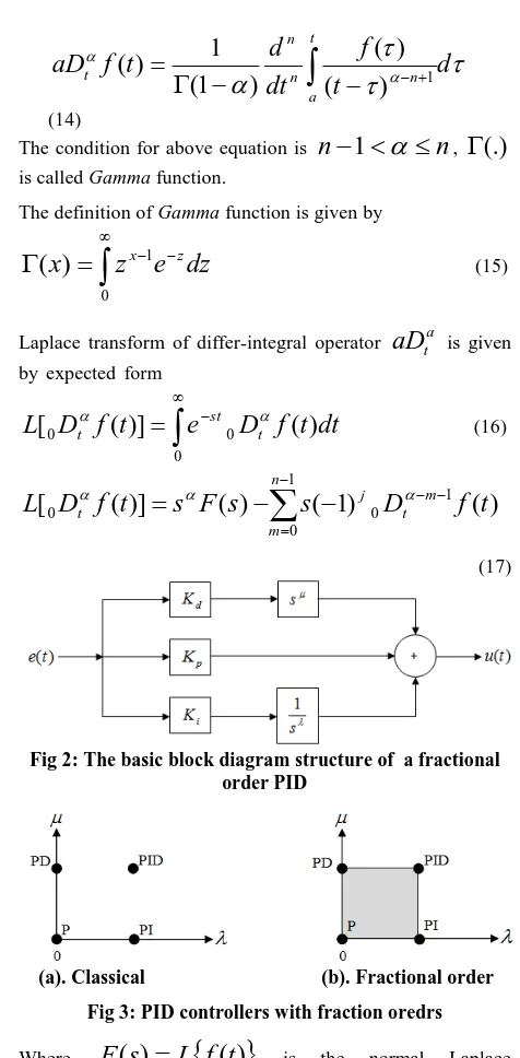
(17)Fig 2: The basic block diagram structure of a fractional order PID
(a). Classical (b). Fractional order
Fig 3: PID controllers with fraction oredrs
Where
F
(
s
)
L
f
(
t
)
is the normal Laplace transformation andn
is an integer number that satisfiesn
n
1
ands
jw
denotes the Laplace transform variable.3.2
Fractional Order PID Controller
Fractional order PID controller denoted by
PI
D
was proposed by Igor Podlubny [4] in 1997. It is an extension of conventional PID controller where λ and μ have non-integer fractional values. Figure 2 shows the block diagram of fractional order PID controller.The integer-differential equation defining the control action of a fractional order PID controller is given by:
)
(
)
(
)
(
)
(
t
K
e
t
K
D
e
t
K
D
e
t
u
p i d
(18) [image:3.595.54.280.435.602.2]FOPID controller is given by:
K
s
s
K
K
s
G
di p
FOPID
(
)
(19) Where
and
are an arbitrary real numbers. Taking
1
and
1
, a classical PID controller is obtained. Thus, FOPID controller generalizes the classical PID controller and expands it from point to plane as shown in Figure 3. This expansion provides us much more flexibility in designing PID controller and gives an opportunity to better adjust the dynamics of control system. This increases the robustness of the system and makes it more stable. [5]. A number of optimization techniques can be implemented for getting the best values of the gain parameters of the controller. In this research, Artificial Bee Colony Optimization (ABC) technique is recommended to tune the controller due to its ability to obtain optimum controller parameters, hence achieve best system response.4.
ARTIFICIAL BEE COLONY
OPTIMIZATION METHOD
The Artificial Bee Colony is a bee swarm algorithm described by Karaboga in 2005. It considers one of the more recent population based optimization algorithm for solving the multivariable numerical functions [1]. The ABC optimization algorithm has advantages of fast convergence high flexibility, strong robustness and fewer control parameters. [16] [17]. In a real bee colony, there are some tasks performed by specialized individuals. These specialized bees try to maximize the nectar amount stored in the hive by performing efficient division of labor and self-organization. The colony of artificial bees consists of three groups of bees: employed bees, onlookers and scouts. First half of the colony consists of the employed artificial bees and the second half includes the onlookers. Employed bees determine a food source within the neighbourhood of the food source, onlooker bees wait on the dance area for making the decision to choose a food source within the neighbourhood of the food sources chosen by themselves, while scouts are responsible for random search of new food sources. For every food source, there is only one employed bee. In other words, the number of employed bees is equal to the number of food sources around the hive. The employed bee whose the food source has been abandoned by the bees becomes a scout. The position of a food source represents a possible solution of the optimization problem and the nectar amount of a food source corresponds to the quality (fitness) of the associated solution. The number of the employed bees or the onlooker bees is equal to the number of solutions in the population [7].
Detailed pseudo code of the ABC optimization algorithm is as follows [18]:
1. Initialize the population of solutions
SN
i
x
i,j,
1
,
2
,...
(SN
is the number of food sources)j
1
,
2
,...
D
,
(D
is the dimension of problem, for optimization of PID controllerD
3
[namelyK
p,
K
i andK
d], and for FOPID controller5
D
[namelyK
p,
K
i,
K
d,
and
]). 2. Evaluate the population.3. Cycle=1.
4. Repeat.
5. Produce new solutions (food source positions)
v
ij in the neighborhood ofx
ij for the employed bees using the formula)
(
ij kjij ij
ij
x
x
x
v
(k
is a solution in the neighborhood ofi
,
is a random number in the range [-1,1] ) and evaluate them6. Apply the greedy selection process between
x
ij andv
ij. 7. Calculate the probability valuesP
ifor the solutionsx
i by means of their fitness values using the following equation:
SNi i i i
fit
fit
P
1
(20)
In order to calculate the fitness values of solutions we employed the following equation:
0
)
(
1
0
1
1
i i
i i
i
f
if
f
abs
f
if
f
fit
(21)Normalize
P
i values into [0,1].8. Produce the new solutions (new positions)
v
i for the onlookers from the solutionsx
i, selected depending onP
i, and evaluate them9. Apply the greedy selection process for the onlookers between
x
i andv
i.10. Determine the abandoned solution (source), if exists, and replace it with a new randomly produced solution xi for the scout using the following equation:
)
min
(max
*
)
1
,
0
(
min
,j j j j
i
rand
x
(22)11. Memorize the best food source position (solution) achieved so far.
12. Cycle=Cycle+1.
13. Until Cycle= Maximum Cycle Number (MCN) .
5.
SPEED CONTROL SYSTEM DESIGN
In this research, PID and fractional order PID controllers based on ABC optimization method are adopted to design the proposed speed control system for DC motor. The block diagram of the speed control system for DC motor is shown in Figure 4. The ABC tuning algorithm was mainly utilized to determine optimal values for controller parameters
d i
p
K
K
%)
(
MO
and steady state error(
e
ss).
Based on (8) and(18), the closed loop transfer function of the proposed speed DC motor control system can be expressed as follows:
3 1
4 5
3 2
1
)
(
)
(
K
s
K
s
K
K
K
s
K
s
K
s
G
cl
[image:5.595.312.541.73.496.2]
(23)Fig 4: Block diagram of speed control of DC motor where
K
1
K
dK
,
K
2
K
pK
,
K
3
K
iK
and)
)(
(
,
5 2 2 4K
K
K
R
Ls
Js
B
K
. The controllers are simulated using Matlab environment to validate the proposed system and their performance is evaluated and then compared based on control criteria which includes: rise time and settling time, maximum overshoot, and steady state error parameters. The system under unit step input is designed to achieve the following control criteria: rise time)
(
t
r less than 1 s, settling time(
t
s)
less than 2 s, maximum overshoot(
MO
%)
less than 5% and steady state error(
e
ss)
less than 1%. The proposed Fitness function)
(
F
for the optimization of both PID and FOPID controller parameters is defined as: ) ( min ) ( max(
1
)
r s ss t t e Moe
w
e
w
F
(24) [image:5.595.51.282.118.307.2]6.
SIMULATION AND RESULTS
In this research, controllers based on PID and FOPID techniques of speed motor control system are designed and simulated using Matlab tool. Parameters of controllers are tuned in optimum fashion based on ABC optimization algorithm. The parameter values taken for running the ABC algorithm in Matlab environment are listed in Table 2. Table 2. Parametric values of ABC algorithm Parameter Value No of food sourcesSN
100
No of onlooker bees
100
Limit (scout trails)
20
No of iterations
100
Run time (MCN)
50
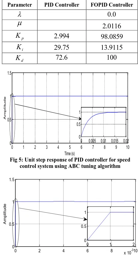
Table 3 states optimum values of PID and FOPID controller parameters for speed control system. Based on these controller parameters, under unit step input, the output response of PID and FOPID controllers for speed control system are shown in Figures (5) and (6) respectively.
Table 3. Parametric values of PID/FOPID controller
Parameter PID Controller FOPID Controller
0
.
0
2
.
0116
p
K
2
.
994
98
.
0859
i
K
29
.
75
13
.
9115
d
K
72
.
6
100
Fig 5: Unit step response of PID controller for speed control system using ABC tuning algorithm
Fig 6: Unit step response of FOPID controller for speed control system using ABC tuning algorithm.
It can be noted from these figures that the ABC optimization method succeeded to tune controllers effectively and hence achieve good output response. Based on mini plots of Figures 5 and 6, the parameters of system performance criteria which include rise time, settling time and overshoot are presented in Table 4. It can be noted from Table 4 that, both controllers based on ABC optimization algorithm satisfied the control requirements, however, there is a good improvement in rise time and settling time is achieved using ABC-FOPID controller. Rise time reduced from 6.5 ms to 0.8 ms while the settling time reduced from 13 ms to 1.9 ms. Consequently, the FOPID controller based on ABC tuning algorithm can be effectively adopted to design a good speed control system for DC motor.
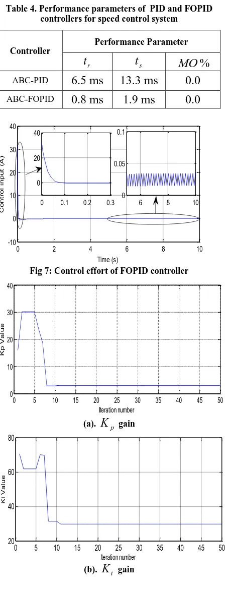
Regarding control system input, Figure 7 shows control effort of speed control system for DC motor using FOPID controller based on ABC tuning algorithm.
It can be seen from mini plot of Figure 7 that steady state value of control input is very small while its initial value is high the reason for this is that the controller parameters are set based on fast response requirement.
0 1 2 3 4 5 6 7 8 9 10
0 0.5 1 1.5
Time (s)
A
m
p
li
tu
d
e
0 0.005 0.01 0.015 0.02 0
0.5 1
0 2 4 6 8 10
0 0.5 1 1.5
Time (s)
A
m
p
li
tu
d
e
0 1 2
x 10-3 0
[image:5.595.71.264.581.678.2]Table 4. Performance parameters of PID and FOPID controllers for speed control system
Controller
Performance Parameter
r
t
t
sMO
%
ABC-PID
6.5 ms
13.3 ms
0.0
[image:6.595.331.560.77.217.2]ABC-FOPID
0.8 ms
1.9 ms
0.0
Fig 7: Control effort of FOPID controller
(a).
K
p gain(b).
K
i gain [image:6.595.320.544.507.662.2](c).
K
d gainFig 8: Generation values of PID controller gains.
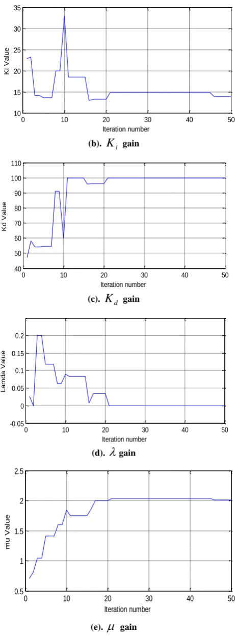
To achieve an acceptable system behavior a compromise between response speed and control effort of the system should be considered in determine the controller gain parameters. Figures. 8 and 9 present convergence curve of gains parameters for PID and FOPID controllers based on ABC optimization method through iterations respectively.
7.
CONCLUSION
This research presents investigation into the development of speed control system for DC motor. The mathematical model of armature current controlled DC motor , which describes the dynamics of the speed control system, was derived. Two controllers, PID and FOPID, were successfully designed and simulated based on Matlab environment for the speed control system. In this study, ABC optimization algorithm has been successfully used to tune the gain parameters of the controllers. Under unit step input, the performance of the optimized ABC-PID and ABC-FOPID controllers was compared based on rise time, settling time and overshoot parameters to evaluate the proposed speed control system. The simulation results have shown that, the FOPID controller based on ABC tuning method had the fastest response with minimal overshoot value. Therefore, FOPID technique can be effectively adopted to design an efficient controller of speed control system for DC motor.
(a).
K
p gain0 2 4 6 8 10
-10 0 10 20 30 40
Time (s)
C
o
n
tr
o
l
in
p
u
t
(A
)
0 0.1 0.2 0.3 0
20 40
6 8 10 0
0.05 0.1
0 5 10 15 20 25 30 35 40 45 50 0
10 20 30 40
Iteration number
K
p
V
a
lu
e
0 5 10 15 20 25 30 35 40 45 50
20 40 60 80
Iteration number
K
i
V
a
lu
e
0 10 20 30 40 50
0 20 40 60 80 100
Iteration number
K
p
V
a
lu
e
0 5 10 15 20 25 30 35 40 45 50 20
40 60 80 100
Iteration
K
d
V
a
lu
e
(b).
K
i gain(c).
K
d gain(d).
gain [image:7.595.55.286.75.700.2](e).
gainFig 9: Generation values of the FOPID controller parameters
8.
REFERENCES
[1] Dhubey, G. K., 2009. Fundamentals of Electrical Drives. New Delhi, Narosa Publishing Home.
[2] Subrahmanyam, V, 2011. Electric Drives: Concepts and Applications, New Delhi, Tata McGraw Hill.
[3] A. Rajasekhar, Sh. Das, and A. Abraham, 2013, “Speed Control of Dc Motor Using Particle Swarm Optimization”. In Proceeding of IEEE World Congress on Nature and Biologically Inspired Computing (NaBIC), 259-266.
[4] Ahmad, A., Saad, Z., Osman, M., Isa I., Sadimin, S. and Abdullah, S., 2010. “Control of magnetic levitation system using fuzzy logic control,” In Proceedings of the IEEE Second International Conference on Computational Intelligence, 51–56.
[5] Mohammed, I. K., Sharif, B. S. and J. A. Neasham, 2012. ”Design and Implementation of a Magnetic Levitation Control System for Robotically Actuated Capsule Endoscopes, In Proceedings. of the IEEE ROSE2012 Conference, Germany, 909-912.
[6] Mishra, A. K. and Narain, A. “Speed Control of DC Motor Using Particle Swarm Optimization”, International Journal of Engineering Research and Technology 1(2012), (13)2, 23-34.
[7] Das S., Functional Fractional Calculus, Springer, 2011. [8] Podlubny, I. “Fractional-order systems and PIλDμ
Controllers, IEEE Trans. Autom. Control, 44(1), 1999, 208-214.
[9] Ercin, O. and Coban, R., 2011. “Comparison of the Artificial Bee Colony and the Bees Algorithm for PID Controller Tuning”, In Proceedings of the IEEE Conference on Innovations in Intelligent Systems and Applications (INISTA). 595-598.
[10] Mickky, A., and Tiwari, B. “Analysis of Speed Control of Separately Excited DC Motor Using FOPID with LQR”, International Journal of Innovative Research in Electrical Electronics Instrumentation and Control Engineering, 2015, 3(3), 47-50.
[11] Kumar, P., Chatterjee, Sh., Shah, D., Shah, U. and Chatterjee, S. “On Comparison of Tuning Method of FOPID Controller for Controlling Field Controlled DC Servo Motor”, Journal of Cogent Engineering 2017, 4(1), 1-20.
[12] Tabari, M. and Kamyad, A. “ Design Optimal Fractional PID Controller for DC Motor with Genetic Algorithm”, International Journal of Scientific and Engineering Research. 2012, 3(12), 1-4.
[13] Rinku, S., Subhransu, P. and Gagandeep, K. Kamyad, “ Design of Fractional Order PID Controller for Speed Control of DC Motor”, International Journal of Scientific and Research Publications, 2012, 2(6), 51-60.
0 10 20 30 40 50
10 15 20 25 30 35
Iteration number
K
i
V
a
lu
e
0 10 20 30 40 50
40 50 60 70 80 90 100 110
Iteration number
K
d
V
a
lu
e
0 10 20 30 40 50
-0.05 0 0.05 0.1 0.15 0.2
Iteration number
L
a
m
d
a
V
a
lu
e
0 10 20 30 40 50
0.5 1 1.5 2 2.5
Iteration number
m
u
V
a
lu