Review Article
Networks for Computing Needs
ASHWIN GUMASTE IIT Bombay
*Author for Correspondence: E-mail: [email protected] Proc Indian Natn Sci Acad 84 No. 2 June 2018 pp. 371-384
Printed in India. DOI: 10.16943/ptinsa/2018/49339
What does it mean?
As computing power grows and follows Moore’s law, material science is unable to meet such computing requirement within a single processor. Extremely large scale integration and device technology that enables us to go to sub-20 nm processes and hence pack millions of logic gates in a single chip. Even such integration is not enough to meet the ever growing needs of users, especially with the world-wide-web throwing a plethora of applications year-on-year. The compounded-annual growth rate (CAGR) of data-traffic in the Internet is almost doubling every other year, and this huge amount of data requires processing that needs to be done across various data-centers in the Internet. Combine that with the disparate requirements of the data such as voice, video based services and crunching for numbers to provide real-time analytics that are quintessential to providing advanced services. The goal of this chapter is to understand what does it mean when processing entities need to be connected to create a virtualized environment to meet user needs. The underlying network becomes a tactical glue that binds many processing entities into a virtualized environment that cumulatively adds the computing power of disparate entities. Networking began as a way to transport data and voice and is now the key enabler for the Internet and all the applications subtended by the growth of the Internet. Networking technologies have progressed through wired and wireless mediums from bit-rates of a few Kbps (kilobits per second) to several hundred Gbps (gigabits per second) in the optical fiber. The deployment of the network as an aid to computing marks an interesting and important revolution in the next generation of computing. In effect, the onus of making processing more rigorous has been replaced by making processors behave as a large single unit
across a network. This makes next generation computing effective and pragmatic from cost, performance and usability standpoints.
Networks have transgressed from copper cables, to shielded twisted pair based cables, to networks in the air (wireless) and to use of the optical fiber. Networks have become smarter from just transporting bits from one place to another to providing application awareness that is quintessential to next generation applications and computing. High Performance Computing (HPC) cannot become pragmatic without the underlying network. The network is used between processors, processors and memories, processor blades and server farms, and between data-centers. Each type of interaction between computing entities (processors, servers, memories) requires a different type of networking flavor — tailored to meet the key aspects of the interaction. Networks for computing needs have transformed processor development and related data-centers theatre seen as the brain of the Internet.
A second important feature that networks provide to HPC is the agility provided due to reconfiguration of the network interconnection graph. Significant research has gone into creating networks that provide reconfigurability. Regular network architectures were initially deployed that had predictable routing indices. These are now been replaced with customizable irregular network fabrics that can create extremely reconfigurable network fabrics — essential for HPC applications.
HPC applications have by themselves become very complex requiring rapid-back-and-forth communication between computing entities such as servers across an interconnection network. Apart from agility there is also the issue of providing one-to-many service across a network backbone. Popularly called as data multicasting the service is critical for easy and fast replication of data from one computing entity to several others in a parallel manner.
Scalability of providing a multitude of network services across an HPC environment is another key feature that measures HPC performance. Another figure of merit for HPC systems is as to how many computing entities (servers or storage devices) can be connected without loss of performance. The trade-off is that when we have N entities that need to be connected, we classically face the N2 problem — that of creating a non-blocking paradigm with N2 cross-bar switches. As N increases, the size of such an interconnection paradigm becomes unmanageable, expensive, and hence difficult to implement. So how do we create next generation HPCs and data-centers with several 10s of thousands of computing entities while meeting the requirements of disparate services? This problem has received substantial attention in the recent past, and we will examine the various approaches towards solving such interconnection paradigms.
From a protocol perspective, there is an interesting yet problematic trade-off that one encounters. Simply put, a protocol data unit (PDU) that can scale, requires significantly larger header implying that for processing the header large amount of time is lost thus compromising on latency. It is no wonder that protocols like Infiniband that have excellent latency do not scale very well. In contrast, protocols such as IP, especially in IPv6 format scales
very well but is plagued by its overhead and control processing implying very poor latency. Much effort has been devoted to the design of scalable yet latency-sensitive protocols. To this end, we will outline the correct protocol requirements that would aid towards the design of next generation protocols for HPC applications.
Application development is what is dictating future HPC requirement. Applications are becoming exceedingly parallel in behavior with both symmetric parallelism and asymmetric parallelism. In symmetric parallelism, entities communicate with each other in a homogeneous parallel structure, while in asymmetric parallelism, a group of M entities are continuously used for communication and computation by a group of N-M entities in an N-node HPC structure. In the latter case, there is tremendous stress on the interconnection fabric, especially when we consider that due to application behavior it is impossible to predict the stochastic behavior of the interconnection pattern between the computing entities.
The last pieces of the HPC interconnection puzzle are security and energy consumption. HPC environment requires higher level of security on account of sensitive applications as well as to conserve processing power on legitimate tasks. Usually, physical security is a first step towards attaining HPC security, but when the HPC machine is connected to the outside world, the degree of security preparedness becomes a challenge. Securing HPC systems in the context of next generation applications and pertinent cyber-threats is of paramount importance in very large HPC clusters. How does one continue to be ahead in the security framework when attacks can be launched by users both legitimate and otherwise?
Networks for Computing
As HPC system grow, the underlying interconnection fabric i.e., the network becomes important. The architecture of the network, its connection methodology and ability to adapt to HPC requirement are all figures of merit to eventually judge the HPC system.
Networks in an HPC system can be classified into three types: on-board interconnects that are capable of connecting chip-sets among each other; server to server interconnects that facilitate intra-HPC interconnection; and data-center to data-center interconnect, as is prevalent to create a cloud computing environment. Each of these classifications requires a different type of network architecture, protocol and connection methodology. We will examine these in detail now.
Chip Interconnection
Chip interconnection has become an important issue in recent times. One can say that chip interconnection technology has made progress in discrete steps. Wire based interconnection on breadboards and rudimentary PCBs were perhaps the first interconnection technology. The number of discrete wires, the line-rate that the wires could support, and distance between chips were all limitations to scaling such an interconnection system. Then came PCB with multiple layers, whereby PCB tracks were used in some of the many layers as an interconnection pattern. The tracks in the PCBs also had limitations in terms of distance and bandwidth they supported. It must be noted here, that as the line-rate between chips increased, the behavior of the tracks had to be carefully analyzed to support such increase. PCB tracks which were regular conductors of the bit-stream running between chips will have extreme waveguide properties exhibited by them, as the line-rate increases. The frequency domain analysis of a high-speed signal (essentially now an RF-signal) will have harmonics that will create a frequency domain response of the track. The track layout and the material used to build the PCB will determine how severe the response would be. As a rule of thumb, higher the permittivity constant of the material used, better its ability to transport high-speed signals. High-speed signal transfer is extremely crucial to achieve the economies of scale in HPC sub-systems.
differential delay between the same clock signal reaching two different chips. Another aspect of differential delay that must be considered is when there are multiple parallel lanes between two chips. Such designs are common between memories and processors or processors and IOs. For example, all RAMs have multiple address and data-lines that are interconnected to the processor. These lines must have exactly the same length on the PCB. If this is not attained then there is the issue of differential delay. Differential delay can potentially lead to loss of synchronization, eventually causing irrecoverable errors. Such errors are very difficult to be rectified in bulk. Lane matching is a well-known technique used to ensure that length of all PCB traces are same that run across two chips and need to act as parallel lanes. The process of layout is hence iterative and involves routing the traces and then ensuring that system parameters are met.
In some cases, the routing and layout problem is done using software in an automated fashion. In most cases, the CAD software for routing and layout is augmented by human intervention. The latter is generally the default industry practice. Simulation models are available to model the signal integrity on traces. There is also a temperature dependent factor that should be considered in HPC environments when PCBs are designed. In most cases, the temperature considered is up to 50oC, but in some industry/military applications we should go up to 70oC to check if the signal integrity is as per what is desired. A very simple way to check signal integrity is to run the simulation model and manually observe the “eye pattern”. If the eye “opens” well enough, then it is quite clear that the signal integrity is intact. If on the other hand the eye opening is negligible then one can assume that it will be difficult to isolate the “0”s from the “1”s.
Future of on-board communication technology: as line-rates increase with processing power, there is an absolute need for on-board technology to change. This change is about to happen. There is a strong research push towards inculcating photonics technologies as an enabler for chip-to-chip communication, popularly called as optical interconnects. Optical interconnect technology is today in its infancy, but is slated to be an important breakthrough for HPC applications. There are two clear advantages of using optical interconnects: optics
through fiber provide for a low loss medium and secondly there is seemingly near infinite bandwidth offered by the optical fiber. Optical fiber is the default choice for communication paradigm for the Internet especially in the core of the Internet. The reliability of the optical fiber as a communication medium is second to none and it serves also as a low-cost medium. Optical fiber is able to provide about 30 THz of bandwidth in its default communication band i.e., when light is transmitted through the fiber at 1.5 micrometers. This translates to 30 Tbps of bandwidth when we deploy simple ON-OFF keying (OOk) techniques. However, current electronics are unable to create a switched bit-stream at such high line-rates. This difference between high-speed optics and low speed electronics is called the opto-electronic bottleneck. To absolve this opto-electronic bottleneck, a solution is to divide the bandwidth into frequency specific channels. Such kind of frequency division multiplexing is commonly deployed to make good use of the optical fiber. Since the frequencies used are of the form of 193 THz (corresponding to 1.5 micrometers), it is more convenient to state the multiplexing pattern as wavelength division multiplexing as opposed to frequency division multiplexing. On each wavelength, we can modulate a slower speed electronic signal and several such wavelengths with individual signals modulated create a composite wavelength division multiplexed (WDM) signal. WDM technology for high-speed communication has significantly matured and it is now a question of time when it would be used as an interconnect technology. When the channels in the WDM signal are spectrally close, then the composite signal is called Dense Wavelength Division Multiplexing (DWDM), while if the channels are far apart in the spectral domain, then the resulting signal is called Coarse Wavelength Division Multiplexed. Multiplexing technology uses optical components such as fused fibers, liquid crystal on silicon substrates, digital lightwave processors (DLP), and interferometers.
generate a coherent source of light. Miniaturization of lasers is a difficult task — it requires substantial semiconductor enhancements and the yield could be substantially low. A key difference between lasers required for commercial optical communications for transmission purposes (long-distance) versus lasers required for optical interconnects in a chip is the power of the laser within the PCB environment is significantly less.
In this regard, an important breakthrough is that of the Vertica Cavity Surface Emitting Laser (VCSEL). Unlike transmission lasers, that require a fiber to be fused into the laser almost perpendicular to the lasing action, VCSELs can be built with fibers parallel to the surface so that the assembly of fibers into the chip can be realistically achieved. VCSELs produce substantially lesser power than lasers, but this is perfectly fine in the ambit of HPC environments where distances are small and the lesser power produced is sufficient to achieve optical interconnections. VCSEL technology is now appearing for directly interconnecting chips in large scale integration. A large number of VCSELs can be grown on the same substrate to create a parallel transmission medium whereby each VCSEL can support a particular frequency, and together they can be coupled together to form a composite WDM signal. Such an arrangement can then be supported by another transmission innovation called plastic fibers, whereby instead of using silicon based fibers, less expensive plastic is used to create the fibers. Plastic fibers are easier to manage and are also more durable to the consumer-centric server interconnect application. It is envisaged that the combination of plastic fibers with VCSEL arrays will form the backbone of optical interconnect applications. The role of photonics is likely to go beyond transmission and communications within HPC environment. It is perhaps possible in the future to have optical processors, whereby wavelength interaction using non-linear effects such as cross-phase modulation and four-wave mixing can create logical gates that work at speeds significantly faster than what is achieved with silicon technology. Newer materials such as Indium Phosphide used for creating monolithic lasers and embedded photonic components would potentially change the interconnection pattern in an HPC environment. Recently, Graphene has been added to the list of materials with smart photonic properties,
and the abundance of Graphene combined with its optical properties is likely to be a game-changer in the HPC interconnection scenario.
Server Interconnection
A second aspect of network interconnection architecture is to connect servers to each other to create an HPC cluster. Server interconnection is perhaps the most important interconnection architecture within the HPC environment. The key challenge to server interconnection is to create a scalable interconnection paradigm. Scalability for network interconnection exists in two forms: (1) scalability in number of servers that can be connected and (2) scalability in terms of performance. The network architecture plays a strong role in determining the performance of the HPC system. There are many possible network architectures to choose from and each architecture has its pros and cons. Typically in contemporary HPC environments or data-centers, servers are represented as blade servers or stand-alone rack-mounted servers. In either case, such servers have front mounted or back mounted interfaces for interconnection. Such IOs, typically are supported inside the server with network interface cards (NICs) that are pluggable modules into the server. The back-end of a NIC is connected via a PCI-express bus. NICs can support a multitude of protocols, but typically the line-rate is either 100 Mbps or 1 Gbps or 10 Gbps. Off late, 10 Gbps server ports are appearing in the market and it is anticipated that there would be an exponential surge towards such adoption in the very near future. Server NICs support two kinds of PHY — either an optical PHY or a copper PHY (physical interface). The optical PHY typically comes with a pluggable optical module, which could be fitted into a PHY-slot that can encompass the module.
There are hence multiple methods of creating modularly scalable interconnection fabrics. Such network architectures usually compromise in some feature of the interconnection fabric.
A commonly used methodology for interconnection fabrics is to use regular graphs. Graph structures such as ShuffleNet, De Bruijn graph, Torus and Hypercube are well known parallel processor environments. The problem with these regular structures is that these do not scale very well. A common mechanism towards interconnection within the HPC environment hence is to stack up switches (generally commodity switches), that facilitate a tree like structure. Usually multiple tiers of nodes are connected across these switches. The advantage of a tree-shaped interconnection topology is that it can be grown quite well with possibility of incremental growth.
The manner in which HPCs are developed using tree shaped interconnection is that a rack of servers is connected to a top-of-the-rack switch (TOR-Switch). Many TOR switches are further back-connected to a root switch. This type of a design requires the root switch to have a large number of ports — equal to the number of racks that are part of the HPC environment. A slightly more scalable design enables multiple levels of root switches so that there is less restriction on the number of ports of a root switch. Yet another efficient design uses multiple paths between any two racks by using a Clos interconnection network between TOR switches. To obtain very large HPC clusters and data-centers, we may break the clusters into pods whereby full non-blocking switching is available within the pod, but across pods only partially non-blocking switching is possible. Such kind of network architecture requires some degree of under-provisioning, whereby the bandwidth in the higher tiers of the architecture is less than the cumulative bandwidth of the servers in the lower layers of the hierarchy. This means that if all the servers in the lower layers of the hierarchy were to communicate with some servers in another branch across the hierarchical TORs, then the TORs would not be able to provision full non-blocking bandwidth between the discrete branches. In fact as the number of servers in an HPC increases, under-provisioning cannot be avoided.
An Example: If we have a 16 client port switch and each servers’ interface is at 1 Gbps, then one TOR can support 16 servers. We assume that the switch has 2-4 network ports to back-haul the traffic from the servers towards the root of the tree. Now assume that the TORs are further back-hauled into an aggregator switch which has 48 ports, each of say 10 Gbps. That means the network ports of the TOR switch will also be at 10 Gbps, and 48 TORs can be connected together. This means that the under-provisioning factor is 10/16=62.5% Now, further let us assume that the HPC just described is part of one module, and several such modules are connected via a core switch. Then what would be the number of ports and line-rates that this core switch would support? Such questions are difficult to answer without choosing the protocol and technology. Each module would cumulatively generate 480 Gbps of data. Even if we assume the aggregator switch has 48 client ports (connected to TORs) and another 48 network ports used for connection to other module, then we have a scalability limitation of 48 modules and an overall under-provisioning ratio of 62.5%. The only way to grow such a system is to replace the core and aggregator switches with larger port-count switches. This may not be possible with current cost and protocol limitations.
Performance
Another factor of importance is to consider the performance of such an HPC system. Within a module, the longest route is of 4-hops long, while for the larger multi-module HPC system, the number of hops is 6. In general, we need 2logD hops where D is the diameter of the HPC cluster. The performance of such a system degrades in terms of both throughput and latency. Latency will be described in detail in the next section.
Servers within an HPC environment can have optical interfaces or copper interfaces. Similarly, TOR, aggregator and core switches can also have copper or optical interfaces. However, for the purpose of reliable transmission at higher line-rates it is always desirable to have optical interfaces. Optical interfaces are crucial from the perspective of provisioning large amount of bandwidth within the HPC cluster.
an HPC environment. One aspect of scalability limitation is that of providing scalability in terms of number of supported server systems. Another aspect is in terms of providing mechanisms for in-situ addition of servers. Both these approaches require the bandwidth of core switches in an HPC to be upgradeable. With increasing line-rates this can be a serious challenge. Copper interfaces have rate-limitations and cannot scale beyond 10 Gbps, and that too can be supported over a few feet. A large HPC environment can be more than few tens of feet, implying that copper based connections will not work. The solution is to use optical interfaces for both reach and support of larger bandwidth.
Optimal Backpane
Another aspect of server interconnection is the recent use of the optical backplane. A backplane is either a switching card that connects many servers together or can be a mating connector set that facilitates any-to-any connectivity. In typical HPC environments, backplanes can be designed using stand-alone switches or mating cards. The job of the backplane is to provide connectivity between servers. It may be passive, in the sense that it may not support switching and connectivity occurs by a broadcast and select architecture. The backplane may be active, in the sense that it may actually support switching. In case of a passive backplane, there need to be enough connectors that provide one-to-many connectivity for each mating server. The idea is that a server that desires to communicate with other servers, does so by sending the data on one of the traces of the backplane. Other servers can all listen to this data and will have to select whether to pick data by this server or any other servers. In this system, if we are
to support K servers, then each server must have the capacity to send data into the backplane, but when it comes to receiving data, each server must be able to receive from any of the K-1 servers. There is typically no scheduling policy or efficient sharing of the backplane in such a design. The limitation of such a design is the number of receptors that can be architected into each server line-card, since the server backplane IO now has to process data that to decipher whether to select or not. An active backplane is shown in Fig. 4.2 below, and consists of many server line cards connected to a switching card. The switching card is the backplane. The switching card could be a stand-alone pluggable unit or could be a mating stationary connector that comes with the HPC chassis. Scalability in such a case is restricted by the number of line-cards that can be connected to the switching card and creating a non-blocking switching fabric to support the line-cards.
[image:7.612.70.546.82.213.2]In both cases, of backplane design there are design limitations in terms of scalability of the HPC fabric. Even when we connect multiple backplanes together, we are encountered with the same limitation of being unable to provide a non-blocking fabric without compromising on efficiency and performance. We could, for example, have a severely compromised under-provisioning ratio and scale up such a system. But then the performance would be acceptable to only certain traffic types. The problems of such a system would be significantly enhanced, if we assume that processors talk to memories or other processors in executing a task using the switching behavior of the larger system. Such a design is complex and must always be optimized for performance. A general figure of merit of the optical backplane is the amount of bandwidth that it can support for switching.
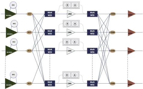
In this regard, recent research has focused on optical backplane design. In lieu of its tremendous bandwidth availability, an optical backplane is proposed as a scalable alternative to traditional electronic backplanes. An optical backplane can be of active or passive type. The active type of optical backplane can be engineered using all-optical switches. All optical switches can be fiber switches — switching signals between ports without analyzing whether the signals are of a particular wavelength; or could be wavelength-level switches. Wavelength-wavelength-level switches are used in commercial core networking technology today and are expected to become more popular as network bandwidth grows. Such all-optical wavelength-level switches are called as Wavelength Selective Switches or WSS. These are primarily of a 1xN design, and a group of these can be collectively engineered to create a non-blocking cross-connect functionality. Shown in Fig. 4.3, is an all-optical switch that can support up to 4 Tbps of bandwidth — better than any electronic backplane. In this design the 1xN WSS is further
[image:8.612.83.533.377.723.2]re-engineered to create an MxN architecture and several such WSS are used together to create an optical switch. Such a large optical switch with wavelength-sensitive properties is also called a Reconfigurable Optical Add-Drop Multiplexer. The architecture is based on the broadcast and select concept, where incoming signal is broadcast to the different arms of the switch, and individual servers can select a wavelength of their choice. The broadcast is done with couplers/splitters, while the selection is done via the MxN WSS. The inherent limitation of this architecture is the switching speed of the WSS. Typically WSS are built using MEMS or LCOS designs and have a switching speed of a few milliseconds which is clearly not acceptable in the HPC environment. Despite this limitation optical switching is being considered by a large number of HPC builders either as an exclusive backplane technology, or as a hybrid technology that has both optical backplane and an electronic backplane. The hybrid backplane is being considered for switching
different kinds of flows. For example, flows among servers can be classified into mice and elephant. Mice flows are those that trickle between servers have low granularity and generally require fast switching — for them the electronic backplane is the best solution. Elephant flows are rare, but when they do happen, they require much coarser granularity and are present for large time-duration. Elephant flows can hence be switched by an optical backplane.
While WSS based backplanes are more scalable than electronic backplanes on account of the larger supported bandwidth — at higher levels there is a scalability limitation.
Yet a third design that is being considered in the backplane is a passive optical backplane. A recent study showed that it was possible to have a near infinitely scalable backplane using passive optics. Such a design also uses a broadcast and select architecture, but the selection process is made much easier using a recently proposed superchannel concept that involves creating OFDM modulated channels in the optical domain. Such a design absolves the need for fast reconfigurable optical switches relying primarily on the broadcast domain for efficient interconnection.
Many HPC systems, each located at different locations need to be connected across these locations to provide a cloud-like environment. Each HPC essentially could be a repository of information and a processing unit. Such an individual HPC environment is called a data-center, and many such data-centers together become a cloud. The architecture of the data-center is quite similar to the architecture of the server-to-server interconnect. Generally the design uses tree shaped topology to connect a server farm at the leaves, with switches at branch and root interconnection points. Such a design is commonly used in small and medium data-centers and HPC clusters up to several 100 nodes or even for 1000 nodes (servers). Apart from the scalability issue of the tree architecture, there is a second scalability issue that of providing protocol support — how do servers talk to each other, discover each other and create a monolithic entity that can be a virtualized environment for computing. Protocols will be discussed subsequently.
Like server interconnection architectures data-center architectures can also have alternate models using some modified form of the Clos switching
architecture where by a combination of smaller port-count non-blocking switches can suffice for a larger switch design.
Data-center design can also be limited by physical space, Internet connectivity and physical location proximity issues. It is very common to deploy many data-centers for a service provider network or many HPC clusters spread across a Wide Area Network. For example, a group of research labs may each have its own HPC cluster with physical proximity to it. All these HPC clusters can eventually be interconnected to form a cloud like environment. Cloud network design is a complex engineering process that often involves managing bandwidth in the WAN that connects the clusters and creating a virtualized environment. Such an environment has to scale as well.
such a technology, the advantage of statistical multiplexing of packets is not available. The dominant network protocol in the Internet is IP, and IP exists as packets or datagrams. IP-packet switching and routing is one of the foundation blocks of the Internet. However, IP as a service is best-effort and not carrier-class. Due to statistical multiplexing and best-effort behavior IP even with MPLS does not offer the same kind of OAMP features that SONET/SDH does. IP can hence be a good residing technology on a SONET/ SDH based VPNs but such a solution is also expensive.
What is required is an efficient packet technology that provides good statistical multiplexing, yet is able to guarantee carrier-class OAMP support. Carrier Ethernet which is a carrier-class alternative of Ethernet is here a good packet alternative. Carrier Ethernet is quite different from Ethernet in the LAN, whereby there is no MAC learning and no spanning tree protocol. This avoids any probabilistic behaviour of finding routes in a broadcast domain and creation of loops. Forwarding in Carrier Ethernet is accomplished based on backbone switch address in conjunction with a series of VLAN tags or labels. Two implementations of Carrier Ethernet exist: in the IEEE and the IETF. The IEEE implementation called
PBB-TE or Provider Bridged Backbone-Traffic Engineering uses VLAN based switching by mapping incoming tagged or untagged services into network-specific ISID tags that are service tags and which are further mapped to backbone MAC addresses and backbone VLAN tags. Forwarding is done exclusively using the 60-bit backbone MAC address and VLAN tags. In PBB-TE, paths are set up using a network management system (NMS) that communicates with core and edge bridges (PBB-TE switches) to assign the requisite MAC and VLAN identifiers. The IETF version of Carrier Ethernet is called Multi-Protocol Label Switching — Transport Profile or MPLS-TP. In this method, labels are used to forward packets and label to packet mapping is again explicitly done through the NMS. MPLS-TP is a scaled down version of MPLS with no merging capabilities as well as no unidirectional support. MPLS-TP also does not support equal cost multiple paths.
[image:10.612.68.541.82.329.2]Three types of services are defined in the gamut of Carrier Ethernet — ELINE, ELAN and ETREE. An ELINE service is a point-to-point bidirectional connection that is created using switched Ethernet identifiers at nodes across the network. An ELAN service is an exemplification of a LAN environment in a core network, while an E-TREE service is one in
which there are many leaves communicating directly to the root of the tree.
In addition to service definitions, Carrier Ethernet also uses the IEEE 802.1ag Connectivity Fault Management standard (or sometimes the Y.1731 standard) to check for faults in the network and ensure a healthy network. As part of the 802.1ag standard, connections are demarcated by management points, and management points exchange information periodically through heart-beat messages. Loss of 3-consecutive heart-beat messages signals to the end points that there is a fault in the connection and hence a graphically alternate (pre-provisioned) path is chosen.
Software Defined Networking (SDN) for Cloud Environments
SDNs are recently being proposed as enablers to launch any service on a cloud like environment, by creating a “dumb” hardware platform into a user-defined switching elements through a control plane. The control plane and data plane interact through well defined Application Programming interfaces and these
are used to describe the user requirements to the hardware. SDNs have the potential of changing the way we plan, route, traffic-engineer and evolve networks.
SDNs are different from traditional networks in the following ways: 1) separation of control and data plane; 2) centralization of the control plane; 3) programmability of the control plane; and 4) standardization of north-bound Application Programming Interfaces (APIs).
SDNs are being used to set up services in cloud like environments with the goal that previous service provisioning methods could only achieve so much and with SDN implementation those horizons are being further extended. By bringing user programmability within the gamut of networking means that new services can be implemented in a network that could previously not be even envisaged.
[image:11.612.68.544.81.377.2]SDNs have the potential of being a game-changer for HPC environment as the user base of HPC is quite diverse implying a strong role for user-defined service support. In such a scenario, SDNs
can control the HPC environment and resources such as bandwidth management can be done through user-defined interfaces. The SDN contribution to HPC is that a traditional symmetric switching environment within an HPC domain can now be made to a user-defined, possibly asymmetric environment.
Scalability Aspects of Network Computing
In this section we delve upon the scalability aspects of HPC systems from the network computing perspective. There are two aspects of scalability to be considered:
l Switch architecture scalability
l Protocol Scalability and fault tolerance
The first aspect of switch architecture scalability has
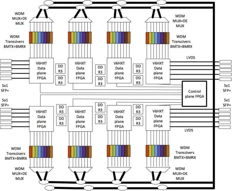
[image:12.612.67.540.332.723.2]been considered in the previous section. Specifically, the N2 connectivity problem is the first impediment towards switch architecture scalability in an HPC environment. Using modified Clos architecture and creating a system of conjugated cross-connects is one approach towards HPC scalability. Using multi-degree backplanes is yet another approach towards achieving switch architecture scalability. This has been described in the previous section. Newer scalable architectures involve the use of optical backplane which have also been shown in the previous section. An example of an optical backplane architecture is described below: In Fig. 4.5 above, a 200 Gbps cross-connect fabric is created using an optical backplane. Each FPGA is part of a processing card, and it emits 10 Gbps data that is modulated onto an optical transceiver (colored). The transceiver is further
multiple computing IO cards. The FPGA is responsible for protocol support and scheduling data onto the backplane. A control card is used to monitor and maintain the health of the network.
Protocols for Network Computing
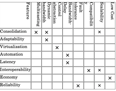
[image:13.612.67.294.81.259.2]In this sub-section we will describe some of the prevailing protocols used in network computing and postulate a Roadmap to describe efficient protocols. Classically the impact of a protocol on a network fabric is quintessential towards making a network efficient. There are many protocols that do similar tasks, and it is important to choose the correct protocol. Unlike large scale networks in the wide-area or even
Fig. 4.6: HPC Features - Network Specifics analysis matrix
connected to an optical channel multiplexer that multiplexes in the frequency domain all the wavelengths, one each from every transceiver in the card. Theoutput of the transceiver is connected to a passive coupler that facilitates adding data into the optical bus. Another coupler is used for drop side communication. The second coupler allows data to be tapped on from any channel. In this way the optical passive backplane facilitates communication between
in local areas, the HPC activity is largely within a cluster or a closed environment, implying that proprietary protocols are just as good as standard backed protocols. A protocol is a method that is agreed between two or more systems to achieve a common set of communication goals. Usually, a protocol is backed with some control mechanism that sets about the protocol in motion.
Impact of Latency on HPC Environments
One of the critical aspects of HPC performance is the end-to-end latency that is experienced amongst HPC machines. Generally larger acluster, worst the latency of the system. In fact, the latency increases non-linearly with the HPC size. Latency is due to protocol processing, queuing and lookups at intermediate nodes and switches. The impact of latency is that it adversely affects virtualization. Most applications cannot be made to work efficiently in a system that is impaired by latency. This is a cause of concern in modern HPC environments. Usually the delay incurred in processing a task is the combination of computational latency and communication latency. Computational latency can be reduced by efficient coding practises as well as parallelizing tasks. Communication latency can be reduced by appropriate choice of protocols and faster interconnect methods. To a large extent, communication latency depends on protocol processing. The larger the protocol overhead required to be processed, the higher the latency.
[image:14.612.76.541.83.289.2]Hence, it makes sense to have more efficient protocols that require minimal processing. To this end, one approach is to keep data in the lower layers of the Internet stack as the processing requirements here are lower. To do so, the granularity of processing in lower layers is much higher than the higher layers, which is not always optimal. A trade-off needs to be attained to process data so that latency is minimized while achieving objectives of communication. Latency also has an impact on virtualization. It is generally preferred that latency be deterministically computed in an HPC environment. It is very difficult to achieve a virtualized computing environment if the latency is probabilistic in nature. Many protocols that require complex forward of information are probabilistic in nature. Protocols such as Infiniband, Fiber Channel and some versions of Ethernet are able to maintain deterministic latency, while most other protocols such as IP and MPLS in cloud environments or Ethernet LANs (primitive Ethernet) are probabilistic in nature.
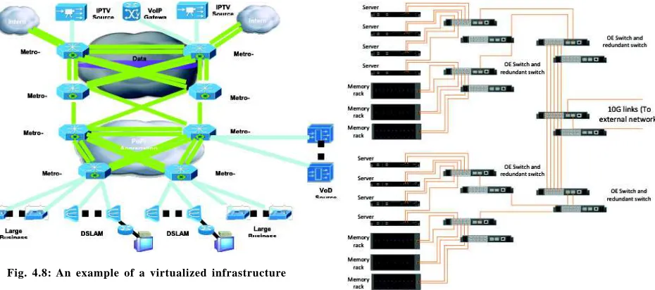
Fig. 4.8: An example of a virtualized infrastructure