© 2016, IRJET | Impact Factor value: 4.45 | ISO 9001:2008 Certified Journal
| Page 1768
"Comparative study on conventional beam slab and flat slab under
various seismic zones and soil conditions”
SAKSHESHWARI
1GURUPRASAD T N
2RAGHU K S
31
PG Student, M.Tech CAD Structures, Dept of Civil Engineering, SIET, Tumkur, Karnataka, India
2
Asst.Professor, Dept of Civil Engineering, SIET, Tumkur, Karnataka, India.
Structural Engineer, SSC R and D Centre Bangalore, Karnataka, India.
---***---Abstract -
Commonly, Flat slab buildings are used for theconstruction because use of flat slab building provides many advantages over conventional beam slab building. The objective of the present work is to compare the behaviour of multi-storey commercial buildings having flat slabs with drop and peripheral beams and beam slab. Present work provides good source information on the parameters base shear, lateral displacement and storey drift. The analysis is carried out by ETABS V9.7.4 software.
Key Words: RC frame building, flat slab, base shear, displacement, storey drift, ETABS.
1. INTRODUCTION
The reinforced concrete frame buildings are commonly used in construction. Flat slabs are one of the most popular floor systems used in residential buildings, car parks and many other structures. Flat slab are favored by both architects and clients because of their aesthetic appeal and economic purpose. The flat slab system is a special structural form of reinforced concrete construction that possesses major advantages over the conventional beam column frame. The flat slab system provides easier formwork, architectural flexibility, unobstructed space, lower building height and shorter construction time.
A flat slab floor system is often the choice when it comes to heavier loads such as multi-storey car parking, libraries and multi-storey buildings where larger spans of free space are also required. Common practice of design and construction is like to support the slabs by beams and next support the beams by columns. This may called as beam slab construction. In normal frame construction uses columns, slabs and beams, however it ought to be potential to undertake construction without using beams, in this case the frame system would comprises of slab and column without beams. These types of buildings are called as flat slabs. The slab directly rests on column and load from the slab is directly transferred to the columns and then to be foundation.
2. LITERATURE REVIEW
Prof. Naveen kumar B M, Priyanka S (2015) “Comparative study of flat slabs and conventional RC
slabs in high seismic zone” The present study covers the
behavior of multistory buildings having conventional RC frame building, flat slabs and to study the effect of height of the building on the performance of these types of buildings under seismic forces. It gives good source information on the parameters storey drift, lateral displacement, natural time period and seismic base shear.
Ms. Navyashree K and Sahana T. S (2014) “Use of flat slabs in multi-storey commercial building situated in
high seismic zones” In this work six number of conventional
© 2016, IRJET | Impact Factor value: 4.45 | ISO 9001:2008 Certified Journal
| Page 1769
Dr. Uttamasha Gupta, ShurtiRatnaparkhe, Padma Gome (2012) “Seismic Behavior of Buildings Having Flat Slabs
with Drops” The main object of this paper is to compare the
behavior of multi-storey buildings having flat slabs with drops with that having two way slabs with beams and to study the effect of part shear wall on the performance of these types of buildings under seismic forces. Present work provides a good source of information on the parameters lateral displacement and storey drift.
Prof. K S Sable, Er. V.A. Ghodechor, Prof. S. B.Kandekar (2012) “ Comparative Study of Seismic Behavior of Multi-storey Flat slab and Conventional Reinforced Concrete
Framed Structures” Tall commercial buildings are primarily
response to the demand by business activities to be as close to each other, and to the city centre as possible, thereby putting intense pressure on the available land space. Structures with a large degree of indeterminacy is superior to one with less indeterminacy, because of more members are monolithically connected to each other and if yielding takes place in anyone of them, then a redistribution of forces takes place. Therefore it is necessary to analyze seismic behavior of building for different heights to see what changes are going to occur if the height of conventional building and flat slab building changes.
3.
DESCRIPTION OF SAMPLE BUILDING
In the study symmetric building models has been taken for all the cases.
Beam slab Building.
Flat Slab with Drop and Peripheral Beams.
A 3D RC frames with 4 bay by 4 bay for 11 (G+10) stories of dimension 28mx28m has been taken for seismic analysis. Effect of RC slab and flat slab with drop and peripheral beams using soil conditions as hard soil, and Soft soil. And seismic zones II, III, IV and V as per IS 1893 (part I):2002.
4. DESIGN DATA
Table- 1:
Geometric Property
Parameter Values
Number of storeys G+11
No. of bays in X
direction 4
No. of bays in Y
direction 4
Bay width in X
direction 7m
Bay width in Y
direction 7m
Storey height 3m
Slab thickness 0.225m
Drop thickness 0.3m
Main Beam size 0.3mx0.6m
[image:2.595.320.486.99.162.2]Secondary Beam size 0.2mx0.6m
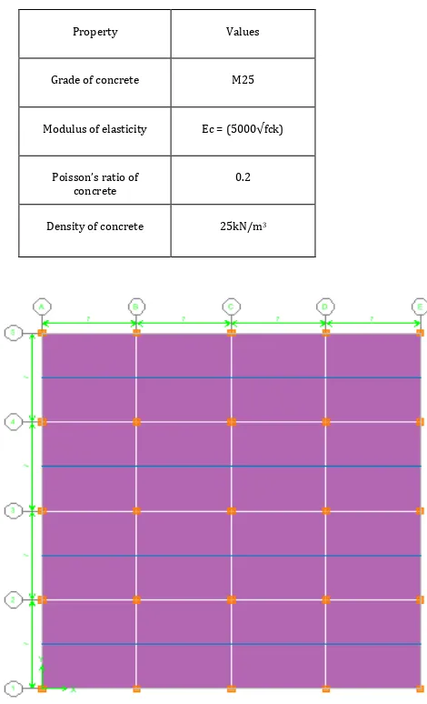
Table -2:
Material Properties of concrete
Property Values
Grade of concrete M25
Modulus of elasticity Ec = (5000√fck)
Poisson’s ratio of concrete
0.2
Density of concrete 25kN/m3
[image:2.595.312.547.194.581.2]© 2016, IRJET | Impact Factor value: 4.45 | ISO 9001:2008 Certified Journal
| Page 1770
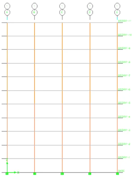
[image:3.595.64.283.390.686.2]Fig 2: 3D View of conventional beam slab building
Fig 3: Model elevation of conventional beam slab building
Fig.4: Building plan for Flat slab building
[image:3.595.335.558.416.706.2]© 2016, IRJET | Impact Factor value: 4.45 | ISO 9001:2008 Certified Journal
| Page 1771
Fig.6: Model Elevation of Flat slab building
5. RESULTS AND DISCUSSION
The following work carried to study the behavior of beam slab building and Flat slab building. The study also includes various parameters which are studied such as base shear, displacement and storey drift. The overall study is conducted by applying the all four seismic zones and different soil conditions are Hard or Rock soil and Soft soil. The seismic analysis for the study has been carried by equivalent static method of analysis.
5.1
Base Shear
Table- 3
: Comparison of base shear along X
directions for different models for rock soil.
ZONES BEAM SLAB FLAT SLAB
Vx (kN) Vx (kN)
II 1132.65 1358.02
III 1631.01 1955.55
IV 1812.24 2172.83
V 2446.52 2933.33
Fig-7
: comparison of base shear along X direction for rock soilTable- 4:
Comparison of base shear along X directions for different models for soft soil.ZONES BEAM SLAB FLAT SLAB
Vx (kN) Vx (kN)
II 1891.52 2267.9
III 2723.79 3265.77
IV 3026.44 3628.23
V 4085.69 4898.65
© 2016, IRJET | Impact Factor value: 4.45 | ISO 9001:2008 Certified Journal
| Page 1772
Above table shows the base shear values for various seismic zones and soil conditions as hard soil and Soft soil for different models, from the above results it can be seen that base shear values are increasing in flat slab system compared to the beam slab system.
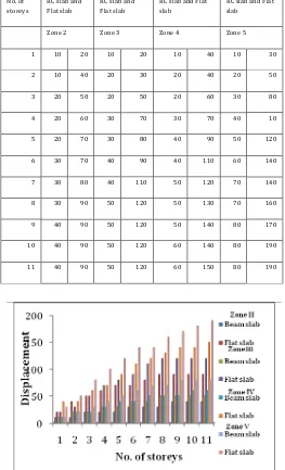
[image:5.595.300.564.127.587.2]5.2 Displacement
Table- 5: Comparison of Displacement (mm) along X
direction for all models for Rock soil
No. of storeys
RC slab and Flat slab
RC slab and Flat slab
RC slab and Flat slab
RC slab and Flat slab
Zone 2 Zone 3 Zone 4 Zone 5
1 10 10 10 10 10 10 10 10
2 10 10 10 20 10 20 10 20
3 10 20 10 30 20 30 20 30
4 10 20 20 40 20 40 30 40
5 10 20 20 50 20 50 30 50
6 20 30 20 50 20 60 40 50
7 20 30 30 60 30 60 40 60
8 20 40 30 60 30 70 40 80
9 20 40 30 70 30 70 40 90
10 20 40 30 70 30 70 40 100
11 20 40 30 70 30 70 40 110
[image:5.595.302.565.131.564.2]
Fig-9: comparison of displacement along X direction for
rock soil
Table -6: Comparison of Displacement (mm) along X
direction for all models for soft soil
No. of storeys
RC slab and Flat slab
RC slab and Flat slab
RC slab and Flat slab
RC slab and Flat slab
Zone 2 Zone 3 Zone 4 Zone 5
1 10 20 10 20 10 40 10 30
2 10 40 20 30 20 40 20 50
3 20 50 20 50 20 60 30 80
4 20 60 30 70 30 70 40 10
5 20 70 30 80 40 90 50 120
6 30 70 40 90 40 110 60 140
7 30 80 40 110 50 120 70 140
8 30 90 50 120 50 130 70 160
9 40 90 50 120 50 140 80 170
10 40 90 50 120 60 140 80 190
11 40 90 50 120 60 150 80 190
Fig-10: comparison of displacement along X direction for
soft soil
[image:5.595.32.272.223.676.2] [image:5.595.29.272.223.684.2]© 2016, IRJET | Impact Factor value: 4.45 | ISO 9001:2008 Certified Journal
| Page 1773
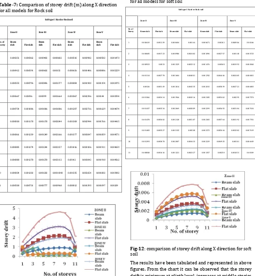
[image:6.595.39.566.113.682.2]5.3 Storey Drift
Table -7: Comparison of storey drift (m) along X direction
for all models for Rock soil
Soil type I Hard or Rock soil
Zone II Zone III Zone IV Zone V
No. of Storey
Beam
slab Flat slab Beam
slab Flat slab Beam
slab Flat slab Beam
slab Flat slab
1 0.000251 0.000362 0.000402 0.000682 0.000542 0.000982 0.000582 0.001473
2 0.000412 0.000591 0.000602 0.00132 0.000656 0.001486 0.000886 0.002229
3 0.000553 0.000796 0.000896 0.001377 0.000884 0.001983 0.001194 0.002975
4 0.000667 0.00096 0.00099 0.001664 0.001067 0.002396 0.00144 0.003594
5 0.000754 0.001086 0.001086 0.001886 0.001207 0.002716 0.001629 0.004074
6 0.000818 0.001178 0.001178 0.002044 0.001308 0.002944 0.001766 0.004415
7 0.000861 0.001239 0.001249 0.002166 0.001377 0.003047 0.001859 0.004571
8 0.000885 0.001274 0.001244 0.002157 0.001416 0.003106 0.001911 0.004659
9 0.000888 0.001278 0.001278 0.002112 0.00142 0.003042 0.001918 0.004562
10 0.000834 0.001202 0.001202 0.0011843 0.001335 0.002654 0.001802 0.003982
11 0.000508 0.000731 0.000777 0.000968 0.000812 0.001393 0.001097 0.00209
Fig-11: comparison of storey drift along X direction for
rock soil
Table -8: Comparison of storey drift (m) along X direction
for all models for soft soil
Soil type I Hard or Rock soil
Zone II Zone III Zone IV Zone V
No. of
Storey Beam slab Flat slab Beam slab Flat slab Beam slab Flat slab Beam slab Flat slab
1 0.000419 0.001139 0.000604 0.00164 0.000671 0.00182 0.000906 0.00246
2 0.000685 0.001723 0.000986 0.002482 0.001096 0.002757 0.00148 0.003723
3 0.000923 0.0023 0.001329 0.003312 0.001476 0.00368 0.001993 0.004968
4 0.001114 0.002778 0.001604 0.004001 0.001782 0.004446 0.002405 0.006001
5 0.00126 0.003149 0.001814 0.004535 0.002015 0.005039 0.002721 0.006803
6 0.001366 0.003414 0.001966 0.004916 0.002185 0.005462 0.00295 0.007374
7 0.001437 0.003534 0.002069 0.005089 0.002299 0.005655 0.003104 0.007634
8 0.001478 0.003602 0.002128 0.005187 0.002365 0.005764 0.003192 0.007781
9 0.001483 0.003527 0.002135 0.00508 0.002372 0.005644 0.003202 0.007619
10 0.001393 0.003078 0.002007 0.004433 0.002229 0.004925 0.00301 0.006649
11 0.000848 0.001616 0.001221 0.002327 0.001357 0.00258 0.001831 0.00349
Fig-12: comparison of storey drift along X direction for soft
soil
[image:6.595.303.565.131.611.2]© 2016, IRJET | Impact Factor value: 4.45 | ISO 9001:2008 Certified Journal
| Page 1774
6 CONCLUSIONS
1) The base shear is maximum at plinth level. The base
shear will increase drastically as the height increases. Base shear of conventional beam slab building is less than the flat slab building. .
2) The base shear is maximum in a soft soil compared
to the rock soil. This shows that mass participation factor is high in flat slab compared to the conventional beam slab building.
3) The displacement of structures increased as the
seismic zone increase in both conventional beam slab and flat slab building.
4) Displacement increases as the height increases for
all the structure. Displacement of flat slab building is more than conventional beam slab building.
5) The displacement is maximum in soft soil compared
to the rock soil.
6) Storey drift in buildings with flat slab construction
is significantly more as compared to the conventional beam slab building.
7) The storey drift is maximum at soft soil compared to
the rock soil.
7 REFERENCES
1) Manu K V1, Naveen Kumar B M2, Priyanka
S“Comparative Study of Flat Slabs and Conventional RC Slabs In High Seismic Zone” International Research Journal of Engineering and Technology Volume: 02 Issue: 06 , Sep-2015
2) Ms. Navyashree K and Sahana T. S. “Use of flat slabs
in multi-storey commercial building situated in high seismic zone”. International journal of Research in Engineering and Technology. (IJRET) ISSN: 2321-7308, Volume-3, Issue-8, and August 2014.
3) Mr. Kiran S. Patil, N.G. Gore, P.J. Salunke. “Minimum
cost design of reinforced concrete flat slab”. International journal of Recent technology Engineering. (IJRTE)) ISSN: 2277-3878, Volume-2, Issue-6, January 2014.
4) Dr. UttamashaguptaShurtiRatnaparkhe, Padma
Gome. “Seismic behavior of buildings having flat slabs with drops”. International Journal of Emerging Technology and Advanced Engineering. (IJETAE) ISSN: 2250-2459, Volume-2, Issue-10, and October 2012.
5) Prof. K S Sable, Er. V A Ghodechor, Prof. S B
Kandekar. “Comparative study of seismic behavior of multi-storey flat slab and conventional reinforced concrete framed structures”. International Journal of Computer Technology and Electronics Engineering. (IJCTEE) ISSN: 2249-6343, Volume-2, Issue-3, June2012.
6) IS: 1893 (Part-I)- code of practice for criteria for
earthquake resistant design of structures, part 1:
general provisions and buildings, bureau of Indian standards, New Delhi.
7) Pankajagrawal and Manish Shrikhande (2006),