2019 2nd International Conference on Informatics, Control and Automation (ICA 2019) ISBN: 978-1-60595-637-4
Design of Mobile Robot Based on Cartographer SLAM Algorithm
Qing GAO
1, Hao JIA
2, Ya LIU
2and Xin-cheng TIAN
2,*1
Enterprise Management and Informatization, Weichai Power Co., Ltd., Weifang, China 261061 2
School of Control Science and Engineering, Shandong University, Jinan, China 250061 *Corresponding author
Keywords: SLAM, Robot localization, Mobile robot, Mapping.
Abstract. Aiming at some problems existing in the development and industrialization of intelligent autonomous mobile robot, the SLAM mobile robot platform is designed and developed in this paper. Cartographer is used as the SLAM algorithm to realize the mapping and localization of the robot in the unknown environment. What’s more, the new hardware design architecture is proposed, and the bottom control module is designed to be applied to the autonomous mobile robot. On the one hand, the design can reduce the workload of the non-algorithm part of the main control unit and improve the real-time of mapping. On the other hand, it solves the problem of communication clogging and enhances the compatibility of the system. Finally, an autonomous test platform is built to test the mapping and localization functions of the robot. The results of mapping, computational complexity and robustness of Cartographer SLAM and Hector SLAM algorithms are analyzed.
Introduction
Intelligent mobile robots are of great significance in accelerating the promotion of intelligent upgrading in various industries and upgrading the level of intelligence in various industries. Simultaneous Localization and Mapping (SLAM) is the core technology to realize intelligent mobile robot, so it has very important research value and theoretical significance. In recent years, with the support of relevant policies and the promotion of market forces, intelligent mobile robots have begun to be applied on a small scale in various industries. From unmanned driving, mine detection, to household sweeping robots, SLAM mobile robots have shown their applications in military, industrial production and daily life [1].
SLAM mobile robots have been applied in deterministic environment such as indoor environment. However, in roadways with similar characteristics and under special conditions such as smoke and dust, there are still some problems, such as poor real-time performance and large accumulated errors, which are far from meeting the requirements of rescue and exploration work. Therefore, it is of great significance to develop SLAM mobile robots that can adapt to harsh environments.
Research on Cartographer SLAM Algorithm
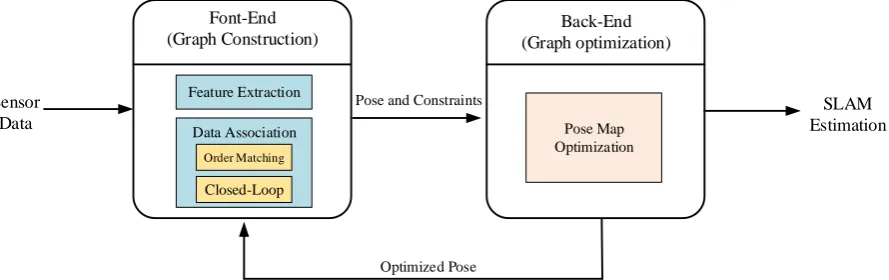
but only optimizes the pose map created by the front-end, and obtains the maximum likelihood estimation of the pose, that is, the optimal pose sequence [2,3]. The algorithm framework is shown in Fig. 1. Font-End (Graph Construction) Back-End (Graph optimization) Feature Extraction Data Association Closed-Loop Order Matching Pose Map Optimization Pose and Constraints
Optimized Pose Sensor
Data
[image:2.595.78.523.117.257.2]SLAM Estimation
Figure 1. SLAM algorithm framework based on graph optimization.
Pose of autonomous mobile robot can be represented by =( x, y, ), x and y represent the
translations in direction x and y, respectively. represents the amount of rotation in a two-dimensional plane. The data measured by the lidar sensor is recorded as 2
1,..., { }k k K, k
H h h .
The initial laser point is 0 and satisfies the requirement of 2
0 . The pose transformation from the scanned data frame of lidar to the submap is recorded as T, and can be mapped to a submap
coordinate system by Eq. 1.
cos -sin sin cos
x
y
t R
T p p
(1)
Continuous scanning lidar data frame can generate a submap, which uses probability grid to express the map model. When the new scanned data is inserted into the probabilistic grid, the state of the grid will be calculated. Each grid has two states: hit and miss. If the grid is hit, the adjacent grids are inserted into the hit set, and all relevant points on the connection line between the scan center and the scan point are added to the lost set [4]. Set a probability value for the grid that has not been observed before, and update the probability of the observed grid according to Eq. 3.
( ) 1 p odds p p
(2)
1
( ) ( ( ( ( )) ( )))
new old hit
M x clamp odds odds M x odds p
(3) Before inserting the laser scanning frame into the submap, it is necessary to optimize the pose of the scanning frame and the current submap by Ceres Solver solver, so that the above problem can be transformed into solving the non-linear least squares problem.
2
1
arg min (1 ( )) K
smooth k
M T h
(4)
mathematical expression of the optimization problem constructed by Cartographer algorithm using sparse pose adjustment method is as follows:
2
,
1
arg min ( ( , ; , )) 2
m s
m S
i j ij ij ij E
(5) 1, , { } m mi i m
and S {Sj}j1, ,n represent the pose of submap and scanning frame respectively under certain constraints. ξij represents the matching position of scanning frame jin the submap and constitutes optimization constraints together with its related covariance matrix
ij . The costfunction of this constraint is expressed by residual and can be calculated by Eq. 6.
1 2
( im, jS; ij, ij) ( im, Sj; ij)T ij ( im, Sj; ij)
E
e
e ,1
; ;
( )
( , ; )
m m S
i i j
m S
i j ij ij m S i j
R t t
e
. (6)
In addition, the Cartographer algorithm also uses branch and bound scan matching algorithm to accelerate the process of closed-loop detection and relative pose calculation.
*
1
arg max ( )
K
nearest k
W k
M T h
. (7)W represents the search window and Mnearest is the extension of M function in the previous section. Identify a window around a new grid, and determine the maximum range of the point set by constantly modifying the angle increment and the maximum range dmax of the sensor [5]. Eq. 8 and Eq. 9 can be derived from the Pythagorean Theorem.
max 1,..., max k k K d h . (8) 2 2 max arccos(1 ) 2 r d . (9)
The integer step length is calculated by the size of the search window so that it can cover the entire search window. x x W w r , y y W w r , W w
. (10)
A finite set of search windows W is formed with the estimation of pose 0 as the center.
x,..., x
y,..., y
,...,
W w w w w w w
. (11)
0 ( x, y, ) : ( ,x y, )
W rj rj j j j j W
. (12) Branch and bound method can efficiently calculate the value of *
Design of Hardware System
Architecture of System Hardware
[image:4.595.209.385.233.450.2]In this paper, the Jetson TX1 embedded platform of Nvidia Corporation is chosen as the main control board [7]. The data collected by lidar is sent to SLAM system through Ethernet interface. SLAM system runs on Nvidia TX1 board. The bottom control module upload the motion state and pose information of the robot to the main control board. The path planning system transfers the calculated robot speed to the chassis drive system through the bottom control module. Thus, the control of mobile robot platform is realized. At the same time, the Cartographer algorithm running on SLAM system sends incremental maps and robot pose to remote industrial computer via WIFI or Ethernet for real-time display. The overall scheme of the hardware is shown in Fig. 2.
Figure 2. Hardware architecture of SLAM robot platform.
After the above work, the whole hardware system is built. The physical and 3D model of SLAM mobile robot platform is shown in Fig. 3.
Figure 3. Physical and 3D models of SLAM mobile robot platform.
Design of Software System
Architecture of System Software
[image:4.595.104.493.508.645.2]Software Design of SLAM System Based on ROS
The software design of SLAM system mainly completes the transplantation of Cartographer algorithm to the self-built SLAM mobile robot platform. Cartographer algorithm is mainly divided into two parts: front-end and back-end. The front-end mainly completes the work of establishing submaps. A certain number of submaps can be used as basic units to form closed-loop detection. Finally, the process of graph optimization is accelerated by branch and bound algorithm. The program implementation process is as follows: First, the function AdHorizonLaserFan() of the local_trajectory_builder is called. This function calculates the robot pose predicted by the pose interpolator as the initial pose to the real-time scanner matcher. Then, the attitude optimized by the real-time scanner matcher is used as the initial pose of the Ceres solver. Finally, scan-to-map is implemented through the Ceres solver to get the final result, and the pose interpolator is updated.
Experimental Verification
Test Environment
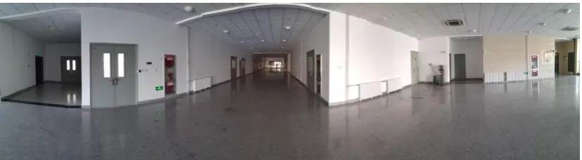
[image:5.595.93.507.366.480.2]In order to test and verify the SLAM mobile robot in multi-dimension, the 2nd floor of Innovation Building of Shandong University is chosen as the test environment. The test scene is about 76 meters long and 38.5 meters wide, and the building area is about 2926 square meters. Because of the large scale of the scene tested and the variety of ground materials, the validity of SLAM algorithm can be tested comprehensively. The test scenario for mobile robots is shown in Fig. 4.
Figure 4. The test scenario for mobile robots.
Test Scheme
Firstly, the robot is guaranteed to run normally in the whole test environment, and the robustness of the two algorithms is tested and compared by manual operation to make the robot rotate at high speed until its rotation acceleration is too large. In order to ensure that the two algorithms run under the same experimental conditions, the Rosbag function package is used to record the sensor data during the experiment, and then the two SLAM algorithms are run through the Jetson TX1 main control board. Finally, Hector algorithm and Cartographer algorithm are used to build environment maps of test scenes. In order to evaluate the mapping accuracy of the two algorithms, the building structure in the measurement environment is measured, and the measured values are compared with those in RVIZ.
Experimental Results and Analysis
Figure 5. Comparison of mapping results between Cartographer algorithm and Hector algorithm.
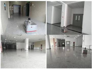
Figure 6. The real-world view of the data acquisition process of the robot.
Conclusion
[image:6.595.116.478.391.664.2]the Cartographer SLAM algorithm is introduced in detail, so as to complete the task of building the experimental platform. Finally, through the contrast experiments between Hector SLAM algorithm and Cartographer SLAM algorithm, it is proved that Cartographer SLAM algorithm performs better in mapping accuracy, robustness and real-time performance.
Acknowledgement
This research was financially supported by the Major Innovation Projects in Shandong Province under Grant No.2017CXGC0601.
References
[1] Siegwart R, Nourbakhsh I R, Scaramuzza D, et al. Introduction to autonomous mobile robots[M]. MIT press, 2011.
[2] Grisetti G, Kummerle R, Stachniss C, et al. A tutorial on graph-based SLAM[J]. IEEE Intelligent Transportation Systems Magazine, 2010, 2(4): 31-43.
[3] Krinkin K, Filatov A, yom Filatov A, et al. Evaluation of Modern Laser Based Indoor SLAM Algorithms[C]//2018 22nd Conference of Open Innovations Association (FRUCT). IEEE, 2018: 101-106.
[4] Xu B, Liu Z, Fu Y, et al. Research of cartographer laser SLAM algorithm[C]//LIDAR Imaging Detection and Target Recognition 2017. International Society for Optics and Photonics, 2017, 10605: 1060509.
[5] Kohlbrecher S, Von Stryk O, Meyer J, et al. A flexible and scalable slam system with full 3d motion estimation[C]//2011 IEEE International Symposium on Safety, Security, and Rescue Robotics. IEEE, 2011: 155-160.
[6] Hess W, Kohler D, Rapp H, et al. Real-time loop closure in 2D LIDAR SLAM[C]//2016 IEEE International Conference on Robotics and Automation (ICRA). IEEE, 2016: 1271-1278.