1
Inter-Cell Interference Mitigation in
LTE-Advanced Heterogeneous Mobile
Networks
Ahmed Basim Atta AL-AALOOSI
Submitted in partial fulfilment of the requirement for the degree of
Doctor of Philosophy
University of Salford
School of Computing, Science and Engineering
I
Table of Contents
Table of Contents --- I List of Figures --- IV List of Tables --- VI Acknowledgements --- VII List of Abbreviations --- IX Abstract --- XIII
Chapter One: Thesis Introduction --- 1
1.1 Research Problem --- 2
1.2 Research Motivation --- 4
1.3 Aim and Objectives --- 4
1.4 Thesis Contribution --- 5
1.5 Research Methodology --- 6
1.6 Thesis Structure --- 10
Chapter Two: Background --- 12
2.1 Introduction --- 12
2.2 Long Term Evolution-Advanced (LTE-A) --- 12
2.2.1 LTE-A Requirements --- 14
2.2.2 Multiple Access --- 14
2.2.3 LTE-A Architecture --- 15
2.2.4 Network Elements --- 17
2.2.5 Cell selection --- 18
2.2.6 Operational Division Duplex --- 19
2.2.7 LTE-A Frame Structure --- 19
2.3 Heterogeneous Deployment of LTE-A --- 22
II
2.3.2 Carrier Frequency Allocation --- 24
2.3.3 HetNet Components --- 25
2.3.4 Technical Challenges in HetNets --- 26
2.3.5 Interference Scenarios in HetNets --- 27
2.3.6 Transmission Mode (CSG, OSG, HSG) --- 29
2.3.7 Cell Range Expansion (CRE) --- 29
2.4 Summary --- 31
Chapter Three: Interference Management in LTE-Advanced --- 32
3.1 Introduction --- 32
3.2 Spectrum Assignment --- 32
3.2.1 Frequency Reuse --- 33
3.2.2 Fractional Frequency Reuse (FFR) --- 34
3.3 Inter-Cell Interference Mitigation in Heterogeneous Deployment --- 34
3.3.1 Power-Domain Inter-Cell Interference Coordination (PD-ICIC) --- 35
3.3.2 Coordinated Multipoint (CoMP) --- 36
3.3.3 Frequency Domain-based Inter-Cell Interference Coordination (FD-ICIC) - 37 3.3.4 Time Domain-based Inter-Cell Interference Coordination (TD-ICIC) --- 38
3.4 Related Work in ICIC --- 40
3.5 Summary --- 46
Chapter Four: The Proposed Scheme for Inter-Cell Interference in HetNet ---- 47
4.1 Introduction --- 47
4.2 The Proposed Inter-Cell Interference Mitigation Scheme --- 47
4.2.1 Physical Resource Blocks Power Allocation --- 50
4.2.2 Prioritisation of Users --- 51
4.2.3 The Proposed User Priority Scheduling Algorithms --- 52
4.3 System-Level Simulation of LTE-Advanced Networks --- 55
III
4.3.2 System Model --- 58
4.3.3 Traffic Model --- 60
4.3.4 Propagation Model --- 61
4.3.5 Signal to Interference plus Noise Ratio (SINR) Model --- 62
4.3.6 Performance Metrics --- 65
Chapter Five: Simulation Results and Discussion --- 67
5.1 Introduction --- 67
5.2 Simulation Results of the proposed scheme --- 67
5.3 Evaluation of the Scheduling Algorithms --- 74
5.4 Comparison with other works in the literature --- 81
5.5 Discussion --- 89
5.6 Summary --- 92
Chapter Six: Conclusions and Future Work --- 93
6.1 Summary of Thesis Contribution --- 93
6.2 Recommendations for Further Research--- 95
6.3 Reflection on the PhD Research --- 97
Appendix I --- 98
Appendix II --- 102
IV
List of Figures
Figure 1-1: Predicted Data demands per month over the next years --- 1
Figure 1-2: ICI problem in LTE-A HetNets --- 3
Figure 1-3: Research Methodology--- 9
Figure 2-1: A graphical illustration of OFDM scheme --- 15
Figure 2-2: LTE-A Reference Model --- 16
Figure 2-3: Radio Frame Structure (type1) --- 20
Figure 2-4: Radio Frame Structure (type 2) --- 20
Figure 2-5: Physical Resource Block (PRB) --- 21
Figure 2-6: Heterogeneous deployment in LTE-Advanced network --- 22
Figure 2-7: Interference Scenarios in HetNets --- 28
Figure 2-8: Cell Range Expansion --- 30
Figure 3-1: Frequency Reuse Schemes --- 33
Figure 3-2: Frame configuration for CA-based ICIC scheme --- 37
Figure 3-3: Example of (ABS) for range expansion in heterogeneous network --- 39
Figure 4-1: Subframe Pattern of the Proposed Scheme --- 48
Figure 4-2: CRE Classification --- 49
Figure 4-3: Users Classification --- 50
Figure 4-4: MUEs Scheduling Algorithm --- 53
Figure 4-5: PUEs Scheduling Algorithm --- 54
Figure 4-6: Network Scenario --- 59
Figure 5-1: Number of offloaded users --- 68
Figure 5-2: Pico UE Throughput --- 69
Figure 5-3: Macro UE Throughput --- 70
Figure 5-4: Total UE Throughput --- 70
Figure 5-5: Cell Throughput --- 71
Figure 5-6: Average UE Spectral Efficiency --- 72
Figure 5-7: Average RBs/ TTI/ UE --- 73
Figure 5-8: Fairness Index among UEs --- 74
Figure 5-9: Pico UE Throughput (Algorithm Evaluation) --- 75
Figure 5-10: Macro UE Throughput (Algorithm Evaluation) --- 76
Figure 5-11: Total UE Throughput (Algorithm Evaluation) --- 76
V
Figure 5-13: Average RBs/ TTI/ UE (Algorithm Evaluation) --- 78
Figure 5-14: Average Spectral Efficiency (Algorithm Evaluation) --- 79
Figure 5-15: Fairness Index (Algorithm Evaluation) --- 80
Figure 5-16: Mean RB Occupancy Percentage (Algorithm Evaluation) --- 81
Figure 5-17: Pico UE Throughput (Comparison with other Schemes) --- 82
Figure 5-18: Macro UE Throughput (Comparison with other Schemes) --- 83
Figure 5-19: Total UE Throughput (Comparison with other Schemes) --- 83
Figure 5-20: Average Cell Throughput (Comparison with other Schemes) --- 84
Figure 5-21: Average RBs/ TTI/ UE (Comparison with other Schemes) --- 85
Figure 5-22: Average Spectral Efficiency (Comparison with other Schemes) --- 86
Figure 5-23: Fairness Index (Comparison with other Schemes) --- 87
Figure 5-24: Mean RB Occupancy Percentage (Comparison with other Schemes) --- 88
Figure I-1: Pico UE Throughput --- 98
Figure I-2: Macro UE Throughput --- 99
Figure I-3: Total UE Throughput --- 99
Figure I-4: Average Cell Throughput --- 100
Figure I-5: Average Spectral Efficiency --- 101
Figure II-1: Pico UE Throughput --- 102
Figure II-2: Macro UE Throughput --- 103
Figure II-3: Total UE Throughput --- 103
Figure II-4: Average Cell Throughput --- 104
Figure II-5: Average Spectral Efficiency --- 105
Figure II-6: Fairness Index --- 106
Figure II-7: Pico UE Throughput --- 107
Figure II-8: Macro UE Throughput --- 107
Figure II-9: Total UE Throughput --- 108
Figure II-10: Average Cell Throughput --- 108
Figure II-11: Average Spectral Efficiency --- 109
VI
List of Tables
Table 2-1: Latency and Throughput of commonly used Backhaul mediums --- 18
Table 2-2: Cell Classification according to ITU-R --- 23
Table 4-1: Simulation Parameters --- 57
VII
Acknowledgements
First and foremost, all the praise to God almighty (Allah) for giving me strength
and power to complete this PhD thesis. Without His blessings, it would have
been impossible for me to complete this research.
I would like to express my deep gratitude to my supervisor, Dr Omar Alani for
offering me an opportunity to work under his supervision and for the valuable
guidance he has given during the period of this research project. I learned a lot
from him on both technical and personal levels. He was always there to guide,
correct, and advise.
I would like to show my enormous respect and gratitude to my family for all
what they have done for me. I am forever grateful to my parents and my sister
for their infinite love and prayers that helped me to pass this vital period of my
life. I owe special heartfelt thanks to my beloved wife for her endless care and
support that strengthened my belief to accomplish my PhD. She was always
there cheering me up and stood by me through the good times and bad.
Furthermore, I would also like to thank all family back home in Iraq for their
unconditional love and encouragement.
I would like to take this opportunity to acknowledge my sponsor, Higher
Committee for Education Development in Iraq (HCED-IRAQ), for granting me
a rare opportunity for a full-sponsorship to pursue my PhD study in the United
Kingdom.
Last but not least, a massive acknowledgement goes to everyone including the
Iraqi cultural attaché, University’s staff, colleagues, and friends, who support
me during the years of research, especially Dr Mohammed Aal-Nouman, for
VIII
I would especially like to dedicate this thesis to my parents, for
whom there are no sufficient words to express my infinite
gratitude and love, and also to my lovely wife for her continuous
IX
List of Abbreviations
3GPP 3rd Generation Partnership Project
AAA Authorisation, Authentication, and Accounting ABS Almost Blank Subframes
CA Carrier Aggregation
CC Component Carrier
CCH Control Channel
CDMA Code Division Multiple Access
CE Cell Expanded
CoMP Coordinated Multipoint CRE Cell Range Expansion CRS Common Reference Signal CS Circuit-Switched
CSG Closed Subscriber Group CSI Channel State Information CSO Cell-Specific Offset DCS Dynamic Cell Selection
DL Downlink
DPS Dynamic Point Selection DSL Digital Subscriber Line DwPTS Downlink Pilot Timeslot eNB enhanced Node B
X FDD Frequency Division Duplex
FD-ICIC Frequency-Domain ICIC
FDMA Frequency Division Multiple Access FeICIC Further enhanced ICIC
FFR Fractional Frequency Reuse
GP Guard Period
GPRS General Packet Radio Services
GSM Global System for Mobile communications HARQ Hybrid Automatic Repeat Request
HetNets Heterogeneous Networks
HO Handover
HOF Handover Failure HPNs High Power Nodes HSG Hybrid Subscriber Group HSPA High Speed Packet Access HSS Home Subscriber Server ICI Inter-cell Interference
ICIC Inter-Cell Interference Coordination IMS IP Multimedia Subsystem
IMT International Mobile Telecommunications IP Internet Protocol
ITU International Telecommunication Union JP Joint Processing
XI
LA Link Adaptation
LP-ABS Low-Power ABS LPCs Low Power Cells LTE Long Term Evolution MAC Medium Access Control
MCS Modulation and Coding Scheme MIMO Multi-Input Multi-Output MME Mobility Management Entity MRs Measurement Reports
NAS Non-Access Stratum NCL Neighbouring Cell List
NGMN Next Generation Mobile Networks OAM Operation and Maintenance
OFDM Orthogonal Frequency Multiplexing
OFDMA Orthogonal Frequency Division Multiple Access OSG Open Subscriber Group
PCC Primary Component Carrier PCI Physical Cell Identity
PCRF Policy and Charging Rules Function PDCP Packet Data Convergence Protocol PD-ICIC Power-Domain ICIC
PDN Packet Data Network PRB Physical Resource Block
XII QAM Quadrature Amplitude Modulation
QoS Quality of Service RA Resource Allocation RAT Radio Access Technology
RE Resource Element
RLC Radio Link Control RNC Radio Network Controller RPS Reduced Power Subframes RRC Radio Resource Control RRH Remote Radio Head
RRM Radio Resources Management RSRP Reference Signal Received Power RSS Received Signal Strength
SCC Secondary Component Carrier SGSN GPRS Support Node
SINR Signal-to Interference plus Noise Ratio TDD Time Division Duplex
TD-ICIC Time Domain-ICIC
TDMA Time Division Multiple Access
UE User Equipment
UL Uplink
UMTS Universal Mobile Telecommunications System UpPTS Uplink Pilot Timeslot
XIII
Abstract
Heterogeneous Networks are one of the most effective solutions for enhancing the network performance of mobile systems, by deploying small cells within the coverage of the ordinary Macro cells. The goals of deploying such networks are to offload data from the possibly congested Macro cells towards the small cells and to achieve enhancements for outdoor/ indoor coverage in a cost-effective way. Moreover, heterogeneous networks aim to maximise the system capacity and to provide lower interference by reducing the distance between the transmitter and the receiver.
However, inter-cell interference is a major technical challenge in heterogeneous networks, which mainly affects system performance and may cause a significant degradation in network throughput (especially for the edge users) in co-channel deployment. So, to overcome the aforementioned problem, both researchers and telecommunication operators are required to develop effective approaches that adapt different mobile system scenarios. The research study presented in this thesis provides a novel interference mitigation scheme, based on power control and time-domain inter-cell interference coordination to improve cell and users’ throughputs. In addition, powerful scheduling algorithms have been developed and optimised to adapt the proposed scheme for both macro and small cells. It is responsible for the optimum resource allocation to minimise the inter-cell interference to the minimum ranges.
The focus of this work is for downlink inter-cell interference in Long Term Evolution (LTE- Advanced) mobile networks, as an example of OFDMA (orthogonal frequency division multiple access)-based networks. More attention is paid to the Pico cell as an important cell type in heterogeneous deployment, due to the direct backhauling with the macro cell to coordinate the resource allocation among cells tightly and efficiently.
1
1
Chapter One: Thesis Introduction
Over the last decades, wireless communications have grown rapidly, and the number of mobile users and their demands have increased exponentially. Accordingly, network planning and optimisation of the current networks became a vital matter for both researchers and mobile operators. The early mobile systems were thrived to satisfy the customers’ needs of voice services. Since that time, frequency planning for these systems and site acquisition were one of the most concerns by the Radio Frequency (RF) engineers. Therefore, industries and mobile operators invested significant efforts in frequency planning and the efficient radio spectrum utilisation. Also, more attention has been paid to the impact of electronic interference, which has a direct impact on mobile network performance. With the increasing demands for mobile data (as shown in Figure 1-1) and the rapid spread of the smart applications on the current mobile devices, the limited spectrum became one of the main constraints in the mobile networks development and supporting higher data rates more challenging.
Figure 1-1: Predicted Data demands per month over the next years [1] 7 11 17 24 35 49 0 10 20 30 40 50 60
2016 2017 2018 2019 2020 2021
E xab yt es p er M on th
2 As a result, it was essential to move from spectrum efficiency towards the network efficiency. One of the effective methods in this field is the network densification, where the same allocated spectrum can be reused in smaller regions to achieve higher spectrum utilisation. However, inter-cell interference management turns into a more challenging issue, especially in mobile networks with heterogeneous deployment (HetNets).
1.1
Research Problem
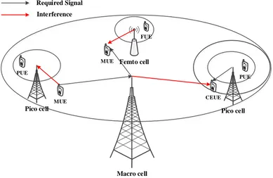
Despite the significant benefits of deploying LTE-Advanced Heterogeneous Networks (HetNets) to increase the network capacity or to extend the coverage in a cost-effective way, Inter-cell interference (ICI) is one of the largest challenges in such networks when utilising co-channel deployment. ICI in such deployments has a negative impact on both user and cell throughputs of all cells in the network. Moreover, traffic balance is directly affected by such interference. Figure 1-2 illustrates the problem of ICI in LTE-A HetNets, where the conventional Macro cell is overlaid by Low-Power Cells (LPCs) to increase the network capacity and to offload more mobile users from the potential congested Macro cell towards these LPCs.
3
Macro cell PUE
Pico cell
PUE
CEUE MUE
Required Signal
Interference
Pico cell Femto cell
FUE
[image:17.595.121.510.76.329.2]MUE
Figure 1-2: ICI problem in LTE-A HetNets
Cell Range Expansion (CRE) concept was suggested to solve the problem of UL interference and to achieve load balance in such types of LTE-A networks. It can be achieved by adding a positive Cell-Specific Offset (CSO) to the RSRP of Pico cells to increase their coverage area and offload more users toward these cells. However, the UEs in Cell Expanded (CE) region suffer from weak SINR and Downlink (DL) interference coming from the Macro cell as a result of biased RSRP and the high transmit power of the Macro cell.
4
1.2
Research Motivation
The radio frequency spectrum is a finite and a scarce resource, which should be optimally utilised when it is being allocated for a certain mobile system. Moreover, the high cost of spectrum allocation is one of the significant challenges for mobile operators.
The ever growing demands for mobile data and the spread of smart devices entails overriding the spectrum efficiency limitations by moving towards the network efficiency. The latter technique mainly utilises network densification to achieve higher performance in mobile networks by deploying small cells for more spectrum reuse and the lower distance between the transmitter and the receiver which results in less path loss. HetNets are one of the essential steps to achieve network densification, by overlaying the traditional Macro cells with LPCs to improve network capacity while keeping the backwards compatibility for old mobile users. However, ICI mitigation is a vital issue for co-channel LTE-A HetNets, which significantly affects the capacity of the network. Most TD-ICIC schemes have a permanent trade-off between the interference mitigation and the available radio resources for some cells, which has a negative impact on the overall network performance.
1.3
Aim and Objectives
5 The principal objectives of this thesis can be summarised as follows:
• Study the impact of the interference on the network capacity of LTE-A networks and explore the current inter-cell interference coordination schemes in LTE-A HetNets. • Survey the up to date ICIC schemes based on the literature, and investigate the effects
of the Almost Blank Subframes (ABS) and the Reduced-Power Subframes (RPS) schemes on both radio resources accessibility and the user protection.
• Design a joint configuration utilising both ABS and RPS in the same scheme, to achieve a balance between the performance of cell-edge users of the LPC and that of the Macro cell UEs.
• Develop powerful user priority scheduling algorithms for both Macro and Pico cells, to provide higher scheduling priorities for all vulnerable users (victim users) in the LTE-A HetNets.
• Design a system model and implement the proposed scheme using DL system-level simulation, taking into consideration all the required modelling calculations and other simulation assumptions.
• Test and evaluate the proposed scheme and the user priority scheduling algorithms according to predefined performance metrics.
• Assess the performance of the final version of this scheme with other TD-ICIC schemes (ABS and RPS) to test the improvement in network performance against the other schemes.
1.4
Thesis Contribution
6 provides increased downlink network performance in terms of user and cell throughputs, which results in total network improvements.
In this thesis, TD-ICIC scheme has been chosen for further improvements as a result of its higher spectral utilisation by sharing the whole available bandwidth between the Macro cell and the LPCs, and the capability of employing higher CRE values which in some cases are necessary to achieve proper load balance in the HetNets. A joint configuration utilising both ABS and RPS in the same scheme has been proposed to achieve a balance between the performance of cell-edge users of the LPC and that of the Macro cell UEs. In this way, the performance of the Macro cell has been optimised while keeping the performance of Pico cells intact, which in turn results in a higher network performance.
1.5
Research Methodology
This research project adopts a research methodology that mainly relies on evaluation and improvement of the proposed scheme using Vienna Simulator. This downlink system-level simulator, which is built on MATLAB, has been modified to support the proposed solution. Feedback from the supervisor and the examiners at meetings, assessments was also working as a guideline during the long journey of the PhD research.
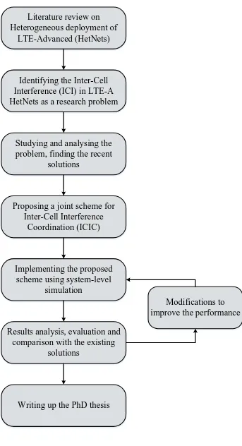
The following research methodology has been adopted in the research program, where the main steps are illustrated in Figure 1-3:
• Literature review on Heterogeneous deployment of LTE-Advanced (HetNets)
7 networks. The supervisor created a roadmap for the research and gave correct guides to choose a critical problem and a novel idea to solve it. Wide literature review on LTE-Advanced and its heterogeneous deployment have been made, to identify the recently employed technologies and their limitations. In the same time, up-to date researches have been investigated.
• Identifying the Inter-Cell Interference (ICI) in LTE-A HetNet as a research
problem
Based on the studied literature, ICI has been identified as a research problem, and the negative impact of ICI on network capacity and the spectrum utilisation have been taken into consideration.
In this stage of the investigation, the problem of inter-cell interference in LTE-A heterogeneous deployment has been recognised as a major issue which severely affects the performance of the network and limits the benefits of deploying the low-power cells within the coverage of the conventional macro cells.
• Studying and analysing the problem, finding the recent solutions
To find a novel solution to the research problem, an extensive study was necessary on the state-of art solutions, analysing their advantages and their limitations. From the literature, several ICIC schemes were found to solve the problem of interference in co-channel HetNet, where two of them are working jointly with CRE to provide inter-cell interference coordination while balancing the load among all cells.
• Proposing a Joint scheme for Inter-Cell Interference Coordination (ICIC)
8 As a result, a joint scheme of using both Almost Blank Subframes (ABS) and Reduced Power Subframes (RPS) has been proposed achieve better results. Developing powerful scheduling algorithms in both macro cell and low-power cell is essential to achieve the aim of this interference mitigation scheme.
• Implementing the proposed scheme using system-level simulation
The implementation of the proposed solution includes system modelling and extensive simulations to get the implementation results. All the system assumptions and the mathematical equations required for the system model has been determined, taking into account the interference from the overlaid macro cell and the neighbour macro cells into account. Unlike some researches in the literature [2], [3], the interference coming from the adjacent low-power cell has also been taken into considerations.
• Results analysis, evaluation and comparison with the existing solutions
Simulation results are significant to analyse the performance of the system under this proposed solution, and taking the necessary measurements which are vital to evaluate the performance of the system. Subsequently, validation is essential to examine the applicability of the proposed scheme in practical life. Moreover, comparing these results with other schemes of the literature is crucial to evaluate the improvement against the existing ICI schemes.
• Writing up the PhD thesis
9 Results analysis, evaluation and
comparison with the existing solutions
Writing up the PhD thesis Implementing the proposed
scheme using system-level simulation
Proposing a joint scheme for Inter-Cell Interference
Coordination (ICIC) Studying and analysing the problem, finding the recent
solutions
Modifications to improve the performance Identifying the Inter-Cell
Interference (ICI) in LTE-A HetNets as a research problem
Literature review on Heterogeneous deployment of
[image:23.595.130.473.63.695.2]LTE-Advanced (HetNets)
10
1.6
Thesis Structure
This thesis is organised into six chapters. The current chapter represents a brief introduction to the PhD research project, which includes the definition of the research problem and the motivation of choosing to tackle such a problem. In addition, the aim and objectives of this research have been outlined. Moreover, the methodology followed in this research has been charted, and all its steps are explained.
Chapter two gives a general overview of the LTE-Advanced network as an example of OFDMA mobile systems. It describes the network architecture and its related elements in both homogeneous and heterogeneous deployments. Furthermore, the radio frame structure and the physical resource block have been explained thoroughly as basic elements in resource allocation.
As a research problem, inter-cell interference (ICI) has been discussed in chapter three, reviewing the spectrum assignments in LTE-A and the main frequency reuse techniques used in homogeneous deployment. The second part of this chapter attempted to classify the ICI mitigation based on the studied literature, describing various mitigation schemes and concentrating on the time-domain inter-cell interference coordination scheme as a result of its higher spectral utilisation and the capability of employing higher CRE values which in some cases are necessary to achieve the proper load balance in the HetNets. This scheme has been chosen for further improvements in this thesis. Therefore, some related works in the literature have been studied and further investigated to give a big picture for the proposed solution in the next chapter.
11 and Pico cells. The next section of this chapter depicts the system model and all simulation assumptions adopted in the system-level simulation. Furthermore, all the necessary equations for network modelling has been specified according to the standards.
All simulation results of the proposed scheme and their findings are shown in chapter five. These results are based on the performance metrics defined in the previous chapter. They also include the evaluation of the scheduling algorithms and validating the proposed scheme by comparing it with other works in the literature to highlight the percentage of network improvements according to the aforementioned metrics. The last section of this chapter depicts a deep discussion of all simulation results, coming up with a clear picture for the next chapter.
12
2
Chapter Two: Background
2.1
Introduction
Since the first version of mobile communications and the concept of cells in 1947 by Bell Labs of USA, the requirements for mobile services and associated applications have grown rapidly to meet the ever-growing demands for more capacity, efficient radio spectrum use, and higher mobility support.
Packet data using mobile systems started commercially in the mid 1990’s, where General Packet Radio Services (GPRS) was introduced in the Global System for Mobile communications (GSM) [4] and in other technologies like PDC standard in Japan. Since that time, the demands for mobile data has continued to rise exponentially, especially following the advancements in mobile terminal technologies. As a result, both researchers and commercial operators have an interest in conducting studies to develop the modern mobile networks to conform to the state-of art mobile data services, taking into account the potential constraints and future demands. So far, Long Term Evolution (LTE) mobile network in all of its releases is considered the most promising system as a part of OFDM technology and can satisfy the ongoing requirements for more advanced mobile data services. The subsequent sections in this chapter are going to outline a comprehensive background on the LTE-Advanced mobile network and its architecture as far as is required for this thesis.
2.2
Long Term Evolution-Advanced (LTE-A)
13 applications and advanced multimedia services to all mobile users with higher data rates, low latency, high mobility, and greater spectral efficiency (about 2-3 times that in HSPA) [5].
The performance of such (packet optimised systems) has been optimised by employing enhanced air-interface protocols, and presenting a Multi-Input Multi-Output antenna system (MIMO), which provides a better quality of received signals and reduces the co-channel interference, and presents Inter-Cell Interference (ICI) aware techniques.
LTE-A can fulfil Link Adaptation, where the Modulation and Coding Scheme (MCS) can be changed sensibly per user or frame, according to the channel conditions. In addition, signal to Interference plus Noise Ratio (SINR) and Hybrid Automatic Repeat ReQuest (HARQ) function can be utilised by the adaptation algorithm to maximise the throughput in the time-varying channel.
Unlike the previous mobile systems, two-dimensional resource scheduling (in frequency and time) can be employed in LTE, which enables multi-users’ transmissions in one time slot.
LTE-Advanced comes to meet the requirements of the 4th Generation by ITU IMT-Advanced. It provides more enhanced services in the case of mobility and seamless handover, keeping the interoperability with traditional GSM and CDMA systems. LTE-Advanced also utilises a layered OFDMA to enhance the whole system performance and increase the spectrum efficiency.
14
2.2.1
LTE-A Requirements
3GPP has set the requirements for the new LTE system to adapt the modern demands of the Radio Access Technology (RAT). The most significant requirements are outlined as follows [6]:
• Scalable architecture with simplified implementation
• Seamless mobility, ensuring the Quality of Service (QoS) for higher speeds • Reduced delays in both transmission and connection procedures
• Increased user data rates, taking into consideration the cell-edge throughputs • Enhanced Inter-Cell Interference (ICI) mitigation schemes
• Reduced cost per bit, with a guaranteed spectral efficiency • Flexible and efficient spectrum usage in all allocated bands • Optimal power consumption, especially for UEs
Furthermore, Next Generation Mobile Networks (NGMN) alliance of network operators [7] serves as an additional guide for development and assessment for LTE design. Network operators’ requirements support the development of the LTE next phase according to IMT-Advanced requirements of 3GPP.
2.2.2
Multiple Access
15 of both FDMA and TDMA for optimum spectrum utilisation in the next generation of mobile networks [8].
OFDMA is based on OFDM concept [9], which divides the available spectrum into multiple orthogonal (overlapped) subcarriers (as shown in Figure 2-1) using Discrete Fourier Transform (DFT) and Fast Fourier Transform (FFT), to be used widely in highly frequency-time variant wireless radio channels [8].
Channel
SC
FDM
OFDM
f
Figure 2-1: A graphical illustration of OFDM scheme
One of the most OFDM distinct features is the flexible and independent operation of the available spectrum (i.e. offering different channel bandwidths with low complexity at receiver side). Therefore, OFDMA has become the basic multiple access technique for LTE-A and the next generations [10].
2.2.3
LTE-A Architecture
16 Therefore, all the services that were traditionally Circuit Switched (CS) are now handled by IP Multimedia Subsystem (IMS) network in LTE.
The LTE architecture, which is called Evolved Packet System (EPS), comprises two parts: the radio part (E-UTRAN), and the network part (EPC) [11], [12].
3GPP designed the Evolved Packet Core (EPC) as a new packet core to support the E-UTRAN (shown in Figure 2-2) with a minimum number of network elements, and allow the connections to other networks easily and in a more functional manner. Moreover, an additional layer of security was already added to LTE-A system, Non-Access Stratum (NAS), to improve the system security between 3GPP and non-3GPP networks; it is also responsible for data ciphering.
[image:30.595.93.502.492.732.2]Other control entities are included in EPC, such as Home Subscriber Server (HSS), and Authorization, Authentication, and Accounting (AAA) server, where HSS is responsible for all the subscribers' information, while the AAA is responsible for user activity tracking, and managing QoS, charging policies through Policy and Charging Rules Function (PCRF).
17
2.2.4
Network Elements
The distinct architecture of LTE-A introduces new control-plane elements to the EPC: • Mobility Management Entity (MME)
A new control-plane Mobility Management Entity (MME) is responsible for new protocol implementation in LTE-A. MME communicates with the HSS for retrieving subscriber information, and with the serving gateway to establish and release the EPS bearers. It communicates with eNB over the S1 interface and supports mobility between 3GPP access networks via an S3 interface with the Serving GPRS Support Node (SGSN) [14].
• Serving Gateway (S-GW)
The main function of the S-GW is packet routing in the LTE-A network and packet buffering when paging a UE. It also acts as a local mobility anchor in case of inter-eNB Handover (HO). Furthermore, it communicates with the PCRF entity for charging control and lawful interception.
• Packet Data Network Gateway (PDN-GW)
PDN-GW is considered the default router to connect the UE of the network to an external Packet Data Network (PDN) such as internet and IMS. It is responsible for UE IP allocation as an LTE-A user can have several IP addresses with different PDNs. It also performs QoS enforcement of the IP (Internet Protocol) packet flow to the UE [15].
• Evolved Node-B (eNB)
18 In light of this, the protocols and functions (PDCP, RLC, and RRC functions) were terminated in RNC, but now they are terminated at eNB itself, which reduces the latency and eliminates the role of the traditional existence of RNC [6].
• S1 and X2 Interfaces
The various elements in LTE-A network are interconnected to communicate and share the network information among them. Different mediums can be used to achieve such connections, while they result in different latency and throughput capabilities, as illustrated in Table 2-1 [16].
Table 2-1: Latency and Throughput of commonly used Backhaul mediums
Backhaul Technology Latency (one way, ms) Throughput (Mbps)
Fibre 2-30 50-10000
Cable 25-35 10-100
DSL 15-60 10-100
Wireless 5-35 10-100, maybe up to Gbps
range
The basic interfaces in LTE-Advanced are X2 and S1; eNBs (such as Macro/ Pico cells) are interconnected through X2 interface. X2 interface is a point-to-point logical interface [17], which can help to exchange the interference and handover-related information and perform the interference coordination between the neighbouring cells. On the other hand, eNBs are connected through S1 to MME. S1 interface supports a many-to-many relationship between MME and eNBs [18].
2.2.5
Cell selection
19 The initial cell selection in LTE-A is done by the UE based on the highest received power from the neighbouring cells [20]. This method is known as Maximum RSRP (Max- RSRP), so the cell with highest RSRP towards the UE will be selected as a serving cell:
𝑺𝑺𝑺𝑺𝑺𝑺𝑺𝑺𝑺𝑺𝑺𝑺𝑺𝑺𝒄𝒄𝑺𝑺𝒄𝒄𝒄𝒄=𝐚𝐚𝐚𝐚𝐚𝐚 𝐦𝐦𝐚𝐚𝐦𝐦
𝑺𝑺∈𝑰𝑰 (𝑹𝑹𝑺𝑺𝑹𝑹𝑹𝑹𝑺𝑺) (2-1) Where i represents the serving cell, and I is the set of all cells in the network.
On the other hand, the stored information cell selection requires stored information of the carrier frequency and cell parameters from the previously received measurements of the detected cells. In this thesis, the initial cell selection of UE idle-mode has been used for all simulation scenarios.
2.2.6
Operational Division Duplex
Both Frequency Division Duplex (FDD) and Time Division Duplex (TDD) modes are considered in LTE-A for uplink-downlink duplexing schemes. FDD suggests different frequencies for both Uplink and Downlink transmission, which should be sufficiently separated whereas TDD implies different and non-overlapping time slots for both transmissions. Therefore, FDD requires a paired spectrum, while TDD can operate in an unpaired spectrum.
FDMA systems mainly use FDD because TDD mechanism is inappropriate in the case of real time voice or multimedia communication, as it requires very tight synchronisation procedures, which may not be viable in some scenarios [21].
2.2.7
LTE-A Frame Structure
20 • Frame structure type 1: where the radio frame is divided into ten equally-sized subframes of 1 millisecond time span, each subframe is composed of two time slots (0.5 ms). Therefore, one radio frame (10 ms) contains 20 time slots. Each radio frame has 307200 Ts (the basic time unit), which is 30.72 MHz, so one Ts equals 1/
(15000×2048) seconds. Figure 2-3 illustrates the radio frame structure type 1, as it will be the standard frame structure used in this thesis.
#0 #1 #2 #3 #18 #19
Subframe
Time Slot = 15360 × Ts = 0.5 ms
1 Radio Frame = 307200 × Ts = 10 ms
Figure 2-3: Radio Frame Structure (type1)
• Frame structure type 2: in this type, the radio frame is divided into two equal half frames, where each half is divided into five equal subframes of 1-millisecond size. Two types of subframes are defined in this frame, as shown in Figure 2-4: special and non-special subframes. The special subframes are subdivided into Downlink Pilot Timeslot (DwPTS), Guard Period (GP), and Uplink Pilot Timeslot (UpPTS), which exist in both halves of the radio subframe.
Subframe #0 Subframe #2 Subframe #3 Subframe #4 Subframe #9
One slot,
Tslot = 0.5
ms
One subframe, Tsf = 1 ms
DwPTS GP UpPTS
One Radio Frame, Tf = 10 ms
21 • LTE-A Physical Resource Block (PRB)
Generally speaking, LTE-A systems simplify the resource allocation by grouping Resource Elements (REs), which are considered the smallest unit of the frame and contain a single complex value of data from a physical channel or signal, into a larger group known as Resource Blocks (RBs) [23]. An RB is defined as the smallest unit that can be allocated to a user by an eNB’s scheduler of the eNB. It represents a time-frequency grid of REs (as shown in Figure 2-5), where each PRB spans 180 kHz and consists of 12 consecutive subcarriers (15 KHz width each) in frequency-domain and 7 OFDM symbols in time domain. However, in the case of using an extended prefix, the number of OFDM symbols will be six rather than 7.
7 OFDM Symbols (Normal Prefix)
12
S
u
b
ca
rri
ers
=
12
×
15
K
Hz
[image:35.595.216.394.358.552.2]Resource Element
Figure 2-5: Physical Resource Block (PRB)
22
2.3
Heterogeneous Deployment of LTE-A
HetNet is one of the most efficient solutions for achieving optimum spectrum and network efficiencies [24]. In some research studies, HetNets have referred to the deployment of different radio access techniques within the same coverage area (Inter-RAT implementation), while in this thesis the term “HetNet” indicates the heterogeneous deployment of LTE-Advanced system where the regular High Power Cells (Macro cells) are overlaid by Low Power Cells (e.g. Pico cells), forming a multi-tier network (as shown in Figure 2-6). Such implementation is used to enhance network capacity and/ or network coverage in different deployment scenarios. Furthermore, such types of network can improve both average and cell-edge users throughputs [25].
F1 (High power)
Macro cell PUE F2 (Low power) F2 (Low power) Pico cell PUE CEUE
CA capable UE
Primary Link Secondary Link
Pico cell Range Expansion region
MUE
Figure 2-6: Heterogeneous deployment in LTE-Advanced network
23
Table 2-2: Cell Classification according to ITU-R [28]
Type A B C D E F G
Cell Radius (m) 289 115 92 69 46 23 11 Tx power (dBm) 46 30 28 26 22 16 10 Antenna height (m) 60 26 24 22 20 18 16
Type C cell size=80% of type B; likewise, types D, E, F, and G cell sizes are 60%, 40%, 20%, 10% respectively compared to type B [28].
2.3.1
Advantages of Heterogeneous Networks
The goals of deploying HetNets are to offload data from the possibly congested Macro cells toward the LPCs, to achieve enhancements for outdoor/ indoor coverage, more spectrum reuse, and to increase the network throughput for cell-edge users. Moreover, it provides better link quality and low power consumption by reducing the path between the transmitter and the receiver. Small cells enhancement has significant importance in 3GPP TR 36.932 and TR 36.842 [29].
The new physical layer design of LTE introduces a flexible resource partitioning among cells of different power classes, to achieve the optimum resource utilisation.
However, interference is a critical issue that affects the operation of HetNets, so advanced techniques for interference management should be carefully chosen. In LTE Release 8, ICIC technique is used to mitigate the downlink interference between cells [30]. Consequently, ICIC techniques were enhanced efficiently in the next successive releases mainly to support co-channel deployment in heterogeneous networks.
24 Femto cells) to cover the gaps between cells and to provide better coverage for a certain number of indoor users is one of the applied solutions [31].
Since there is no X2 interface defined between Macro/ Femto cells to enable interference
coordination techniques, interference management for co-channel deployment can be done through Operation and Maintenance (OAM) and power control techniques (in Release 10) to minimise the link failure due to interference.
Studies on Release 12 and onward focus on network densification to meet the increasing demands for high-speed applications without affecting the scarce spectrum. In turn, such deployments require the development of the number of radio and protocols solutions to achieve that gain [27].
2.3.2
Carrier Frequency Allocation
Due to some regulatory limitations and heavy usage of the recent spectrum, most heterogeneous deployments focus on same-frequency operations (intra-frequency) wherein Macro/ low-power cell layers share the same carrier frequency(s).
3GPP has identified Release 12 requirements in TR 36.932, where different scenarios for heterogeneous deployment are suggested:
I. Macro/ low-power cells share the same carrier frequencies (Intra-frequency) [32], [33].
25 layers. However, such enhancement comes with the price of multiple carriers’ usage, and Inter-frequency handover, which consumes more time and terminal battery life [34], [35]. On the other hand, Intra-frequency deployment is spectrum efficient since it can provide better resources partitioning [32] but it is more challenging to mitigate the cross-tier interference and mobility management between cells using the same carrier frequencies (especially in CE region) [36]. These two challenges require a robust UE solution to overcome such interference in heterogeneous deployment.
The availability of higher frequency bands (e.g. 3.5 GHz) can support better spectrum usage by using separate spectrums for each layer, which leads to minimised interference between the two network layers. Frequency-separated deployments can be used to exploit both duplex schemes (FDD/TDD) to achieve better performance [37]. Dynamic TDD is possibly beneficial in local area coverage, where the network can dynamically choose between UL and DL according to the instantaneous needs [38].
2.3.3
HetNet Components
HetNets follow the same architecture of any A network (as described in section LTE-A LTE-Architecture). However, several types of cells with different characteristics could be deployed in such networks, forming a multi-tier network:
• Macro cells: refer to the conventional eNBs, which are installed by operators to provide open access to all users subscribed to the network. This type of cell has a high transmit power of up to 46 dBm and covers a wide area of a few kilometres. It is utilised to serve thousands of users with a minimum guaranteed data rate and tolerable delay.
26 outdoor environment [39]. They provide open access for all users of the network when Macro cell capabilities are insufficient for dense areas.
• Femto cells: this term describes the low-power cells (up to 23 dBm) used to provide unplanned deployment by users for indoor environments (e.g. office, mall, etc.). This type of cell features some access restrictions for certain users, as they are deployed by the customers, and they utilise other types of backhauling (e.g. DSL) to reach the mobile network.
• Relay nodes: refer to the access points used to route the data from Macro cells to the users to extend the coverage in new areas. They use wireless backhaul to connect the Macro cells and have limited capabilities as compared with other low-power cells.
2.3.4
Technical Challenges in HetNets
As a result of different power characteristics of cells (e.g. transmit power, power control settings) [40], HetNet has several challenges, which have significant impacts on the potential achieved performance of this type of deployment. Based on the literature, the most major challenges can be outlined as follows:
27 • More frequent handover due to smaller footprints of low-power cells, which leads to more signalling overhead. Signalling overhead could be minimised by using an RRC inactivity timer, where RRC connection is released by the base station when there is no data activity, which leads to less handover signalling overhead. Furthermore, it can be reduced when releasing inactive UEs during the handover process. A shorter RRC inactivity timer leads to less handover signalling overhead compared to connection setup overhead [41].
• Interference from Macro cell to low-power cells which causes underutilisation in low-power cells (which is the most effective challenge for many deployments) [42].
• Cell selection (especially for UE in CE region).
• UL interference due to shifted handover boundaries toward the low-power cells.
• Mobility robustness: due to the more frequent handover, heterogeneous deployment leads to more handover failure (HOF), which has a negative impact on the Quality of Service.
• Backhauling limitations between the Macro cell and low-power cell (e.g. there is no direct interface between the Macro cell and Femto cell).
2.3.5
Interference Scenarios in HetNets
28
Macro cell PUE
Femto cell Pico cell
FUE
MUE MUE
Required Signal
[image:42.595.135.476.75.290.2]Interference
Figure 2-7: Interference Scenarios in HetNets
Uplink (UL) interference: Normally, the Macro UE (MUE) receives high transmit power from the serving Macro cell, and at the same time it transmits with high power in UL as well. For Macro/ Pico cells co-channel deployment, both cells share the same radio resources, so the Pico cell close to that Macro cell receives high UL interference from all MUEs located in its proximity [43]. In some cases, there is a UL interference coming from MUEs to the Femto cells, but it is mostly negligible due to the restricted access nature of these Femto cells.
Downlink (DL) interference: The main DL interference in HetNets is caused by Femto cells of CSG access because they still have high transmit power on MUEs in their neighbourhood while they reject those UEs from accessing their resources. There is another possible DL interference coming from Pico cells towards the MUEs in their vicinity [25], which needs to be considered in the proposed scheme in this thesis.
29
2.3.6
Transmission Mode (CSG, OSG, HSG)
Several access modes are identified in LTE-A HetNets to regulate the UEs access to the network:
• Closed Subscriber Group (CSG): It is the most restricted access mode, which is mainly defined for the Femto cells. In this mode, only predefined UEs have the exclusive permission to connect the Femto cell [44].
• Open Subscriber Group (OSG): Where all UEs in the network has the right to connect the open access cells.
• Hybrid Subscriber Group (HSG): In this mode, the highest priority access is for the predefined UEs; subsequently, the rest of the UEs can access that cell according to the available resources [45], [46].
2.3.7
Cell Range Expansion (CRE)
Conventionally, cell selection in LTE systems is done by a UE based on Maximum RSRP (Max. RSRP) among several surrounding cells [47]. As a result of different power characteristics in heterogeneous networks, this results in less offloaded users from Macro to the low-power cell, which leads to load imbalance in HetNets.
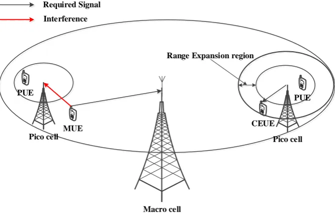
CRE is one of the recent solutions to solve the problem of UL interference. In this concept, the low-power cell RSRP is positively biased by a CSO, as shown in Figure 2-8 to increase their DL coverage [2], and to overcome the situation of fewer users offloaded from Macro cell towards the low-power cell [44], [45].
30
Macro cell PUE
Pico cell
PUE
CEUE MUE
Required Signal
Interference
[image:44.595.137.473.74.288.2]Pico cell Range Expansion region
Figure 2-8: Cell Range Expansion
Maximum gain can be achieved by adjusting handover boundaries between the Macro cell and low-power cells.
Neighbouring Cell List (NCL) is periodically broadcast by the serving cell to facilitate users in monitoring air interface; this list includes neighbouring cells and their pilot signals. UE performs channel measurements and reports the results to its serving cell periodically [3], [50], which in turn decides whether to start HO procedures via exchanging HO-related command message [51] with the target cell. If the serving cell receives a measurement report (MR) from a UE about Pico cell, it will add a bias to the Downlink Received Signal Strength (DL RSS) pilot signal coming from that Pico cell (Pico RSRP). DL RSSs are usually averaged and filtered by UEs in both frequency and time domains to cope with signal fluctuation caused by channel fading [52].
31 strength between Macro/ low-power cell in CE region drops less than this bias value. “CRE may be useful for the Macro cell to reduce the number of handovers” [35]. Employing a positive bias is necessary to improve load balance in HetNet [48].
However, fixed bias value could not adapt the change in user distribution over time, so it is important to dynamically adjust the RE region according to the system performance feedback, to achieve the optimum load balancing and better cell-edge user throughput while maintaining the overall cell performance.
2.4
Summary
This chapter gives a background to LTE-Advanced as an example of OFDM networks, describing the main features and requirements of such networks. LTE-Advanced architecture, network elements, and the frequency planning have been explained in relation to the purpose of this thesis. Both operation duplex division schemes (FDD, TDD) have been summarised, giving the features of FDD to provide a more realistic implementation in the case of real-time voice and multimedia services over the TDD scheme. Their significance in Resource Allocation (RA), especially in co-channel deployment, radio frame and the physical resource block structures, has been discussed thoroughly.
32
3
Chapter Three: Interference Management in
LTE-Advanced
3.1
Introduction
Two main types of interference management have been highlighted in most mobile systems: Interference cancellation [55] and interference mitigation [56]. The first type of interference management is implemented on the received signals by subtracting the interfering signals to allow only the required signals from being decoded successfully. Despite the fact of achieving high capacity, the implementation of interference cancellation in mobile systems may result in high process complexity to estimate the interfering signals [57]. As a result, interference mitigation has gained more attention to prevent the interference before its occurrence. This mitigation can always be achieved by frequency planning, power control, and antenna planning. Mobile networks operators have several spectrum bands, which should be carefully utilised to achieve higher capacity while maintaining the lowest levels of interference.
3.2
Spectrum Assignment
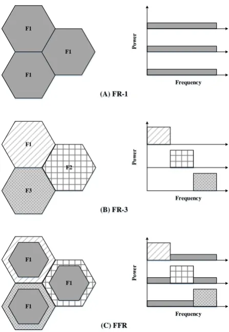
33 capacity while avoiding the unnecessary interference resulting from the frequency reuse. Each set of base stations (cluster) should be allocated a certain number of radio channels, where any adjacent base stations must utilise a different set of channels to avoid any excessive interference, especially in cell-edges. In this way, the same set of radio channels can be reused several times in other clusters safely. Several frequency reuse schemes have been adopted, as shown in Figure 3-1:
[image:47.595.193.417.240.565.2]F1 F1 F1 F3 F1 F2 F1 F1 F1 F1 F1 F1 Frequency P o we r Frequency P o we r Frequency P o we r (A) FR-1 (B) FR-3 (C) FFR
Figure 3-1: Frequency Reuse Schemes
3.2.1
Frequency Reuse
34 interference mitigation with the price of less available capacity for each cell. In this scheme, the total bandwidth is divided into three orthogonal (non-overlapped) sub-bands to be allocated for adjacent cells safely. However, poor throughput may be achieved as one-third of the available bandwidth will be accessible by each cell [60].
3.2.2
Fractional Frequency Reuse (FFR)
As a trade-off between throughput and interference in the schemes mentioned above, Fractional Frequency Reuse (FFR) has been introduced to make a compromised solution [61], [62].
Inherently, UEs in cell-centres experience high signal quality and they are more protected against the interference resulting from neighbouring cells. On the other hand, cell-edge UEs are prone to higher interference and receive a degraded signal due to their far location to their serving cell. As a result, the cell-centre of every cell in the network employs frequency reuse factor-1 with lower transmit power, while the cell-edges operate frequency reuse factor-3 with full transmit power [60], [31]. In addition, other types of frequency reuse schemes are employed in Homogeneous networks, but they are beyond the scope of this thesis.
3.3
Inter-Cell Interference Mitigation in Heterogeneous
Deployment
35 Several spectrum assignments have been adopted in heterogeneous networks for efficient spectrum utilisation. One of these assignments is the fully-dedicated spectrum, where a different set of spectrum bands are assigned for the Macro cells and low-power cell. In this approach, the cross-tier interference is totally avoided. However, the limited spectrum share for each tier results in low spectrum efficiency which has a negative impact on the network performance. Therefore, shared spectrum (co-channel deployment) can offer higher spectrum utilisation but with the cost of high interference possibilities that necessitate a well-planned inter-cell interference coordination in such implementations. The next subsections will discuss some of the most efficient techniques to mitigate the ICI problem based on literature.
3.3.1
Power-Domain Inter-Cell Interference Coordination (PD-ICIC)
36 maintain the required throughput of all attached UEs when using different power allocation on some RBs [63].
3.3.2
Coordinated Multipoint (CoMP)
It is a technique developed by 3GPP for LTE-Advanced (Release 11 and onward) to send and receive data to/ from several points to ensure the optimum performance regarding cell-edge and system throughputs [64]. The primary difference between the standard MIMO and CoMP is that the transmitters in the latter are not physically co-located.
The idea behind this technique is to enable dynamic coordination of transmission and reception over several base stations, to turn the Inter-Cell Interference into a useful signal, especially at cell borders where the problem of ICI increases [65]–[67]. Several types of CoMP have been introduced, which are defined for the downlink as follows:
• Joint Transmission (JT): This is a type of spatial multiplexing when more than one point cooperate so that UE data is transmitted simultaneously from several points. • Dynamic Point Selection (DPS): In this case, all points share the UE data, while
only one point is chosen to transmit this data according to the coordination of all surrounding points.
Other types of coordinated scheduling and beamforming are also defined where UE data is only available and transmitted from a single point, but all points coordinate their scheduling decisions and resource allocation inside the cooperating set.
37 between adjacent cells and a backhaul with a minimum latency are essential to implement this scheme.
3.3.3
Frequency Domain-based Inter-Cell Interference Coordination
(FD-ICIC)
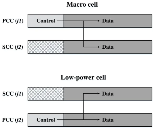
According to 3GPP standards in [68], CA is considered a prominent method of performing frequency-domain ICIC. Interference in DL control channels can be mitigated by partitioning the component carriers (CCs) in the cell layers into two different sets: Primary Component Carrier (PCC) for data and control, while the Secondary Component Carrier (SCC) is mainly for data (or also for control if power control applied) [35]. Figure 3-2 illustrates such a CA-based ICIC scheme. Carrier aggregation is used by both Macro cell and low-power cell layers where both layers enable data communication over f1 and f2. The
Macro cell includes the control information only on f1 while low-power cell includes the
control information only on f2.
Data Control
Data PCC (f1)
SCC (f2)
Macro cell
Data
Data Control
SCC (f1)
PCC (f2)
[image:51.595.173.439.468.699.2]Low-power cell
38 By using this simple mechanism, the control signalling for the different layers is separated. In such a case, the Macro cell adopts the carrier f1 as the PCC while applying power control
schemes on carrier f2 to minimise interference on low-power tier. Similarly, low-power cell
utilises f2 as the primary carrier and applies power control schemes on f1.
Most researchers focus on Control Channel (CCH) interference [69], while few papers concentrate on both data and control signalling interference where the interference is mitigated by reducing the transmit power of some CCs of the macro cell which leads to less network capacity [70]. The above scheme, however, has the constraint that the different layers need to be time synchronised.
3.3.4
Time Domain-based Inter-Cell Interference Coordination
(TD-ICIC)
The time domain-based ICIC schemes basically rely on reducing the transmission activity on certain subframes by each of the cell layers to minimise interference to the victim layers [71], [72]. These subframes are indicated as Almost Blank Subframes (ABS).
This solution is suggested by 3GPP LTE-A (Release 10) to solve the problem of low DL signal quality in cell expanded region and to reduce the PDCCH outage which causes link failure. Moreover, it can overcome the case of larger cell expanded region that causes more interference in DL [73]–[75].
39 both networks layers (macro/ low-power cell layers) should exchange ABS subframe information to achieve the required performance [69].
#0 #1 #2 #3 #4 #5 #6 #7
Macro cell
Pico cell
Normal Subframe
Almost Blank Subframe
#8 #9
#0 #1 #2 #3 #4 #5 #6 #7 #8 #9
Protected Subframe
Frame Duration
Figure 3-3: Example of (ABS) for range expansion in heterogeneous network
According to [77], ABS technique can improve both cell-edge and cell throughputs as a result of using these protected subframes by some Pico users as well, where Macro cell keeps silent through these subframes.
The simulation results of [76] show that both average and the cell-edge throughputs of the low-power cells (e.g. Pico cell) can be dramatically enhanced when employing ABS technique as a result of reducing DL interference for Pico users when Pico cell uses protected sub-frames for data transmission.
In HetNets scenario with CRE and ABS interference coordination, it is noted that data rates of offloaded user highly depend on the amount of ABSs rather than the bias value (especially from a user perspective), as a result of limited scheduling opportunities of offloaded users within ABSs.
40
3.4
Related Work in ICIC
3GPP has suggested TD-ICIC as a time-domain multiplexing technique for cross-tier interference mitigation in LTE Release 10 HetNets [54], which is called Almost Blank Subframes (ABS). In this technique, the aggressive node should refrain from transmitting data on a certain amount of spectrum (subframes or resource blocks) to be protected for the cell-edge users of the victim node that shares the same frequency band(s). In this way, only cell-specific reference signals (CRSs) [78], [79] and other synchronisation and paging signals will be transmitted through these subframes to keep the backwards compatibility with older versions of LTE UEs. Moreover, CRSs are used for radio resources management and channel estimation, so they are necessary to still being transmitted during these subframes. A scheduler has been proposed in [80] which effectively coordinates the inter-cell interference for vulnerable users of LTE-A HetNets with a minimum efforts of coordination using dynamic FFR. In this work, a decentralised resource allocation algorithm is embedded in the framework of LTE to avoid the interference on the cell edge users while maximising the sum throughput of the cell. The proposed scheduler exploits X2 interface to inform the neighbour cells with the reserved resources for its vulnerable users. Therefore, the results show substantial gain as compared to the standard schedulers.
41 A large CRE for a given Pico cell requires larger ABS duty cycle (ratio of ABS to non-ABS subframes) to provide the desired QoS to PUEs in expanded region with the price of degraded MUE performance. Macro cell ABS duty cycle calculation with a load balance algorithm is proposed in [82] to offer a largest possible number of ABS to Pico cells while controlling MUE performance to achieve better spatial reuse. The load balance algorithm can be summarised when each Pico cell estimates the worst PUEs on their associated SINR on both ABS and non-ABS subframes. Based on achievable rate got from SINR, Pico cell decides to schedule those users with worst SINR on the suitable subframe. A dynamic cell selection framework is suggested in [83] for eICIC with two cell association algorithms: one for pure load balance and opportunistic approach for varying cell conditions. Besides this algorithm, an autonomous fast distributed muting algorithm suitable for irregular network deployment is developed for efficient eICIC. These two algorithms show higher capacity gains depending on the deployment environment.
Dynamic configuration of ABS ratio has got a significant interest to adapt the variation in network load. The effect of dynamic ABS according to a certain criterion is studied in [84], [85], [86].
42 the high computation complexity during the joint computation, which could not adapt the prompt channel estimation in the network. As a result of this computation complexity, it takes 5-15 minutes to update the eICIC parameters, which increases the configuration outage especially in the case of significant load changes over the network.
Moreover, [88] proposes a dynamic ABS scheme based on Genetic algorithm for the optimum ABS ratio and location to mitigate the inter-cell interference efficiently for video streaming traffic in Macro/ Pico deployment with shared bandwidth. This scheme proves an improved user throughput and less outage probability when the ABS percentage has been suggested to be 10%, 50%, and 70% for 9, 12, and 15 dB bising, respectively. The simulation results show lower Macro throughput in low biasing values (e.g. 9dB) as a result of higher users connected to the Macro cell. Moreover, the ABS ratio has been proved to be set jointly with the biasing value to provide sufficient resources for all users in the network. However, this scheme has been applied for video streaming only and the ABS configuration was not fully dynamic. The conclusion shows that such configuration outperforms the static allocation only in higher CSO (for the full-buffer case) thanks to the higher load in CE region, while the static configuration is sufficient in lower CSO values since there are no many users in CE region in the latter case.
As mentioned earlier that cell association in LTE is essentially based on RSRP, so it is a critical issue to choose the appropriate CRE values in heterogeneous deployment to maintain a sufficient SINR for the users in that region.
![Figure 2-2: LTE-A Reference Model [13]](https://thumb-us.123doks.com/thumbv2/123dok_us/8683007.875167/30.595.93.502.492.732/figure-lte-a-reference-model.webp)