,
.lias
EU
I
« H a » '^W? ■ · -'Hi
mmm
IMMUNITY
m
EURATOM
INSTRUMENTS
FOR RADIATION DETECTORS
β Ι Ι ΐ A N D CONTROL SYSTEMS®
H
'"tilfl- "íli'^OÍfHi ¡MU
»BlttUi;-.
R. BENOIT*, E. DE BLUST*, L. ISABELLA**, V. MANDL*,
and G. MELANDRONE*
Neither the EURATOM Commission, its contractors nor any person acting on their behalf : B f f i P J ^ ^ Make any warranty or representation, express or implied, with respect to the accuracy, completeness, or usefulness of the information contained in this document, or that the use of any information, apparatus, method, or process disclosed in this document may not infringe privately owned rights ; or
Assume any liability with respect to the use of, or for damages resulting from the use of any information, apparatus, method or process disclosed in this document.
û
hn-i
afe v v '
fe» his report is on sale at the addresses listed on cover page 4
mmmë
D M 4 , Lit. 620 Fl. 3.60
When ordering, please quote the EUR number and the title, which are indicated on the cover of each report.
Salt? Ete .^fiwâr j^ejf
Printed by L. Vanmelle, s.a. Brussels, August 1966
EUR 3063.e
ELECTRONIC INSTRUMENTS FOR RADIATION DETECTORS AND CONTROL SYSTEMS by R. BENOIT*, E. DE BLUST*, L. ISABELLA**, V. MANDL* and G. MELANDRONE*
* Euratom ** CEI, Milan
European Atomic Energy Community — EURATOM
Joint Nuclear Research Center — Ispra Establishment (Italy) Chemistry Department — Nuclear Chemistry
Brussels, August I960 — 34 Pages — 30 Figures — FB 50
Electronics instruments developed in the Nuclear Chemistry Laboratory of the Chemistry Department are described. They include low noise amplifiers for solid state detectors and gridded ionization chambers, fast electronics, power systems for the construction of lithium drifted semiconductors detectors and automatic controls for activation analysis and radiochemical separations.
EUR 3063.e
ELECTRONIC INSTRUMENTS FOR RADIATION DETECTORS AND CONTROL SYSTEMS by R. BENOIT*, E. DE BLUST*, L. ISABELLA**, V. MANDL* and G. MELANDRONE*
* Euratom ** CEI, Milan
European Atomic Energy Community — EURATOM
Joint Nuclear Research Center — Ispra Establishment (Italy) Chemistry Department — Nuclear Chemistry
Brussels, August 1966 — 34 Pages — 30 Figures — FB 50
EUR 3063.Θ
EUROPEAN ATOMIC ENERGY COMMUNITY - EURATOM
ELECTRONIC INSTRUMENTS
FOR RADIATION DETECTORS
AND CONTROL SYSTEMS
by
R. BENOIT*, E. DE BLUST*, L. ISABELLA**, V. MANDL*,
and G. MELANDRONE*
* Euratom **CEI, Milan
1966
Joint Nuclear Research Center Ispra Establishment - Italy
CONTENTS
1. Introduction 3 2. Low noise amplifiers for semiconductor detectors and
gridded ionization chambers by R.Benoit and
G.Melan-drone 3 3. Fast Electronics for time measurements with
photo-multipliers and semiconductor detectors by
L.Isabel-la and V.Mandi 7 4. Power Supplies and Control Systems for the
construc-tion of Lithium Drifted Semiconductor Detectors by
E. De Blust 12
5. Automatic Controls for t h e A c t i v a t i o n Analysis and
Radiochemical S e p a r a t i o n s by G.Melandrone 13
6. References H
7. Caption of f i g u r e s 15
SUMMARY
1. INTRODUCTION
The aim of this paper is to describe briefly the electronic instruments which have been developed in the Nuclear Chemistry Laboratory during the last years. These instruments have been designed and built in con-nection with the research activities of the laboratory
and are subdivided into the following branches:
Low noise amplifiers for semiconductor detectors and gridded ionization chambers.
Past electronics for time measurements with photo-multipliers and semiconductor detectors.
Power supplies and control systems for the construc-tion of lithium drifted semiconductor detectors. Automatic control for activation analysis and radio-chemical separations.
The main electrical characteristics of each instrument developed are indicated and for some of these the circuit diagram is given. Their performance in physical measure-ments are specified and other possible fields of
applica-tion are menapplica-tioned.
All the instruments described have been tested for long periods of operation and have shown good reliabili-ty.
2. LOW NOISE AMPLIFIERS POR SEMICONDUCTOR DETECTORS AND GRIDDED IONIZATION CHAMBERS.
by R.Benoit and G.Melandrone
Semiconductor detectors and gridded ionization cham-bers are characterized by extremely good intrinsic energy resolution. Our effort was focused on developing electro-nic instruments which could take full advantage of these characteristics. Por this purpose low noise charge and voltage sensitive preamplifiers, high gain linear
- k
-fiers, and pile-up detectors were developed.
2.1 Low noise charge sensitive preamplifiers for semiconduc-tor detecsemiconduc-tors.
Three types of charge sensitive preamplifiers for different types of semiconductor detectors have been built. They are:
a) preamplifiers for high capacitance and high leaka-ge current detectors such as surface barrier types b) general purpose preamplifiers for medium
capacitan-ce and medium leakage current, (small surfacapacitan-ce bar-rier and silicon lithium drifted detectors)
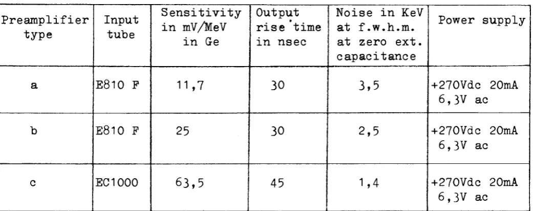
[image:8.595.29.551.441.647.2]c) preamplifiers for low capacitance and low leakage current detectors, (germanium lithium drifted). The main electrical characteristics of these three types of preamplifiers are given in Table 1.
TABLE 1
LOW NOISE PREAMPLIFIERS
Preamplifier type a b c Input tube E810 F E810 F EC1000 Sensitivity in mV/MeV in Ge 11,7 25 63,5 Output rise time in nsec 30 30 45
Noise in KeV at f.w.h.m. at zero ext. capacitance 3,5 2,5 1,4 Power supply +270Vdc 20mA 6,3V ac +270Vdc 20mA 6,3V ac +270Vdc 20mA 6,3V ac
5
-for this purpose, and the tubes were aged -for a period of 100 hours before being selected. The block diagram of this curve tracer system, with a typical plot of an EC 1000 tube, is shown in Fig. 2. The grid voltages,Vg, and the grid currents, Ig, for different plate voltages, Vp, are recorded on an X-Y plotter; first with the switch SW1 in pos. 1 and than in pos. 2. The grid current is proportional to the difference between plots 1 and 2, as shown by the dashed line.
A type c preamplifier circuit is shown in Fig. 3· In this circuit a cascode input configuration with bootstrap has been used in order to increase the signal to noise ratio and the dynamic input capacitance.
The performance of the type b and c preamplifiers is re-ported in Figs. 4 and 5. These show the resolution in KeV at FWHM (Full Width Half Maximum) for a germanium detector (W = 2.8 eV/electron-hole pair) vs. the shaping time con-stants. One RC differentation and one RC integration of equal time constant are considered and the curves aie plot-ted using the external capacity as a parameter. This mea-surement was performed by injecting a known quantity of charge at the preamplifier input and using the root mean square voltmeter method described by Gillespie(l) and Fairstein(2). in the upper parts of the Figures are shown
the energy resolution vs. the total input capacitance mea-sured at the optimal time shaping constant.
The typical performance of these preamplifiers_is shown in Fig. 6 . In the upper part is reported an e spectrum of Cd1^9 performed with a b type preamplifier and a Silicon Lithium Drifted Detector cooled to -90°C. In the lower part is plotted an e spectrum of Cs137 per-formed with a c type preamplifier and the same detector as above cooled to -175°C.
2.2 Voltage sensitive preamplifiers for gridded ionization chambers.
Different types of preamplifiers with a cascode in-put, followed by a bootstrapped cathode follower, in or-der to increase the open loop gain, have been designed and tested. The following tubes have been used at the input: E180F, E83F, 404A, E88CC.
These have been selected for their high transcon-ductance to grid current ratio.
6
-to the maximum of the grid current curve, (where elec tronic current is negligible). The ratios of transcon-ductance vs. grid current for the two tubes these con ditions are the following:
Vp in volts
50
60
70
80
90
gm in A/V/Ig i n A
E83F
0,544x 109
0,736x 109
0,738x 109
E88CC
3,6 χ 109
1,96x 10⁹
1,17x 10⁹
1,03x 10⁹
The theoretical signal to noise ratio can than be cal culated (taking into account the input capacitance of the tube), and the tube itself can be selected.
The best results were obtained with the preampli fier shown in fig. 9 using an E88CC at the input. This tube was placed inside the ionization chamber in order to reduce the stray capacitances.
A typical alpha spectrum obtained with this pre amplifier, using the best E88CC selected among twenty tested tubes and with RC pulse shaping, constants of
Τ = RC int = RC diff = 2us, is shown in Fig. 10. Fig. 11 shows the FWHM vs. shaping time constants f (r) of this preamplifier obtained by injecting a known charge from a pulse generator. The external capa citance was 10 pF.
2.3 High gain linear amplifiers.
7
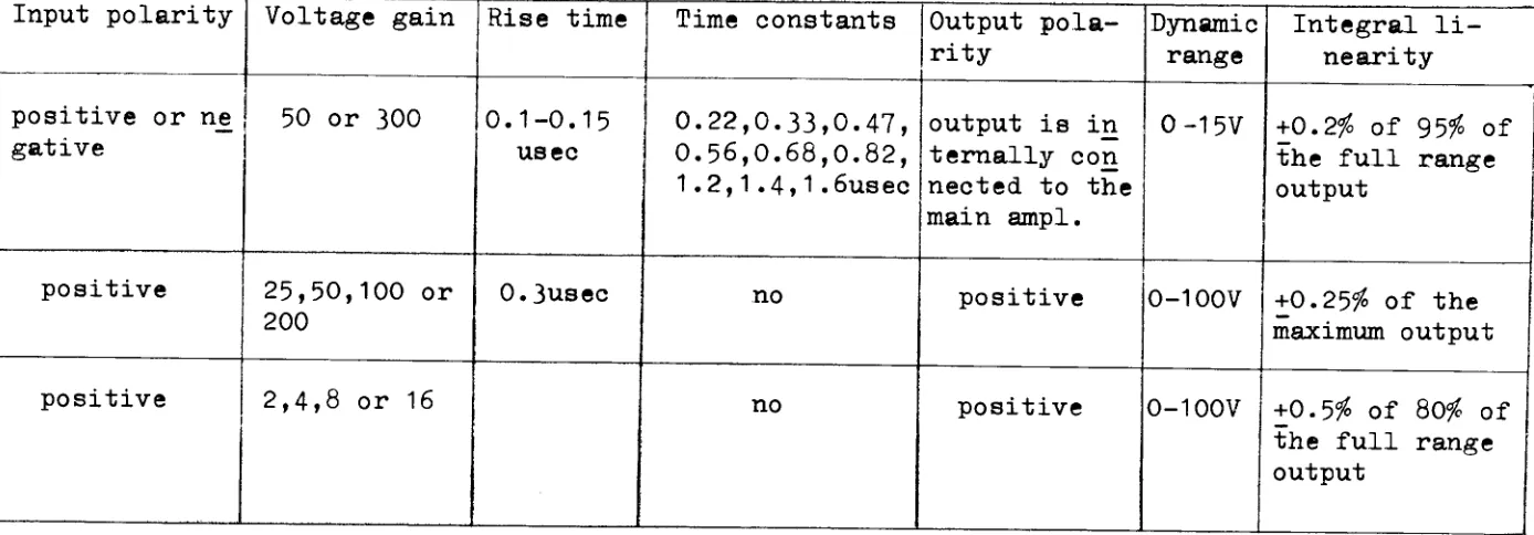
-The gain is stabilized by internal feedback, and the principal characteristics of the amplifier and its different parts are reported in Table 2. These amplifiers are a modified version of the ORTEC Model 201 low noise amplifier in which a set of variable RC time constants and an input amplifying loop were added.
2.4 Pile-up detection circuit.
A pile-up detection circuit which rejects two or mo-re superimposed on closely spaced events in a time range from 5 to 500 usee was developed and is described in re-ference (3)· The circuit also provides the possibility of cancelling two or more pulses superimposed on their front edges and is used in connection with linear ampli-fiers described in Sec. 2.3. The schematic diagram is il-lustrated in Fig. 12.
3. FAST ELECTRONICS FOR TIME MEASUREMENTS WITH PHOTOMULTI-PLIERS AND SEMICONDUCTOR DETECTORS.
by L.Isabella * and V.Mandi
A fast counting system in the time domain of nanose-conds has been developed. The input cricuits were desi-gned to work either with fast photomultipliers such· as types 56AVP and XP 1020 (manufactured by Phillips) or with semiconductor detectors. The parts were assembled in shiel-ded modular plug-in units and are operated from a common power-supply of -20, -10 and +10 Volts.
Transistors and Germanium tunnel diodes were used, and the input and output impedance were kept at 50 ohm. Most signals have negative polarity, 0.5 V output amplitude, across a 50 ohm load. Coaxial 50 ohm transformers have also been built and are used to invert the signal polarities, when required.
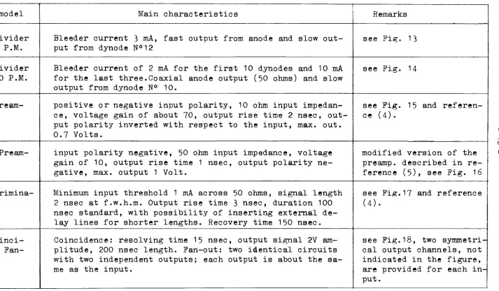
The instruments which have been developed, and their main characteristics, are listed in Table 3· This equip-ment, up to now, has been used for time resolution
mea-surements on fast photomultipliers (principally XP 1020) and for alpha-gamma and alpha-electron coincidences. The results obtained in the field of time resolution measure-ments with photomultipliers are reported in references(10)
and (11). The half-life determination of the 73.6 KeV le-vel of Np239j performed by the delayed coicncidence tech-nique, is described in reference(4)· In this measurement a photomultiplier has been used for detecting the gammas and a surface barrier semiconductor detector for the alphas.
I O o
[image:12.842.100.794.234.476.2]I
TABLE 2 HIGH GAIN LINEAR AMPLIFIER
Part Input lo-op (volta ge sensi-tive) Main am-plifier Post am-plifier (0-100V threshold) Input polarity
positive or ne gative
positive
positive
Voltage gain
50 or 300
25,50,100 or 200
2,4,8 or 16
, Rise time 0.1-0.15 usee 0.3usec Time constants 0.22,0.33,0.47, 0.56,0.68,0.82, 1.2,1.4,1.6usec no no Output pola-rity
output is in ternally con nected to the main ampi. positive positive Dynamic range 0-15V 0-100V 0-100V Integral li-nearity
+0.2$ of 95$ of the full range output
+0.25$ of the maximum output
Alpha-electron and alpha-gamma coincidence measurements of Bi212 with Lithium Drifted Semiconductors detectors are still in progress. Refering to Table 3 both types of amplifiers were developed for semiconductor detectors since the gain of recent P.M.'s is sufficiently high so that no further amplification is necessary.
The discriminator, in its most recent version, uses a Ge 1N3716 tunnel diode with a peak current of 4.7 mA, and has a time walk of about 2 nsec for input signal am-plitudes from 100 to 500 mV. XP 1020 P.M. output pulses were used for this measurement and the test conditions are illustrated in Fig. 25. A hydrogen discharge lamp(4) was used to generate short light pulses, of about 1.5 nsec f.w.h.m., and a system of "polaroid" lenses was used to vary the light intensity over a central area of 1" diame-ter on the photocathode. This collimation was used to si-mulate the experimental conditions of the PM with a 1"x1"
scintillator crystal and to avoid transit time jitter from the center to the border of the photocathode. The PM out-put controls the STOP inout-put of the Time to Pulse Converter
(TPC) which is started on each flash of the hydrogen lamp. These START signals are picked off by means of a capaciti-ve antenna which is sensiticapaciti-ve to the current through the
lamp. The output of the TPC is analyzed with a 256 channel pulse height analyzer.
Two different types of TPC have been developed. The first one is a START-STOP type, i.e. two inputs with dis-tinct characteristics are used and the signal at the START input must always precede the one at the STOP input. This converter also has a gate which can control the START si-gnal, and is triggered with an external pulse which normal-ly comes from a coincidence.
The second converter is of the pulse overlap type and the two inputs are symmetrical. In this circuit the coinci-dence is obtained from the same signals which enter the converter and a simpler circuit configuration is achieved with about the same performances as in the first type con-cerning the measured time internal, overall linearity, and stability.
TABLE 3 FAST ELECTRONIC CIRCUITS
Type and model
Voltage divider for 56AVP P.M.
Voltage divider for XP1020 P.M.
Model 1 Pream-plifier
Model 10 Pream-plifier
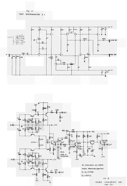
Fast discrimina-tor D1
Double coinci-dence and Fan-out
Main characteristics
Bleeder current 3 mA, fast output from anode and slow out-put from dynode N°12
Bleeder current of 2 mA for the first 10 dynodes and 10 mA for the last three.Coaxial anode output (50 ohms) and slow output from dynode N° 10.
positive or negative input polarity, 10 ohm input impedan-ce, voltage gain of about 70, output rise time 2 nsec, out-put polarity inverted with respect to the inout-put, max. out. 0.7 Volts.
input polarity negative, 50 ohm input impedance, voltage gain of 10, output rise time 1 nsec, output polarity ne-gative, max. output 1 Volt.
Minimum input threshold 1 mA across 50 ohms, signal length 2 nsec at f.w.h.m. Output rise time 3 nsec, duration 100 nsec standard, with possibility of inserting external de-lay lines for shorter lengths. Recovery time 150 nsec.
Coincidence: resolving time 15 nsec, output signal 2V am-plitude, 200 nsec length. Fan-out: two identical circuits with two independent outputs; each output is about the sa-me as the input.
Remarks
see Fig. 13
see Fig. 14
see Fig. 15 and referen-ce (4).
modified version of the preamp. described in re-ference (5), see Fig. 16
see Fig.17 and reference (4).
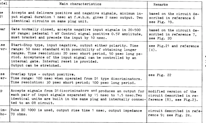
TABLE 3 Continued
Type and model
Double pulse stretcher S1
Double linear Gate G1
Time to pulse height conver-ter C1
Time to pulse height conver-ter C10
Fast pile-up detector
High input im-pedance catho-de follower
Main characteristics
Accepts and delivers positive and negative signals, minimum in-put signal duration 1 nsec at f.w.h.m. gives 2 nsec outin-put. Two identical circuits on same plug unit.
Gate normally closed, accepts negative input signals in 20-500 mV range; pedestal 1 mV Control signal positive 0.5V amplitude, must bracket and precede the input by 10 nsec.
Start-Stop type, input negative, output either polarity. Time range: 50 nsec standard with possibility of obtaining longer ranges. Time resolution: 20 psec short period, 50 psec long pe-riod. Acceptance of the input signal can be controlled by an internal gate. Internal reset is provided.
Output can be stretched.
Overlap type - output positive.
Time range: 100 nsec when operated from D1 type discriminators. Time resolution: 30 psec short period; 100 psec long period.
Accepts signals from D1 discriminators and produces an output for each pair of input signals separated by 15 nsec to 1.5 nsec.Two identical units are built in the same plug and internally connec-ted to an OR circuit.
Tube EC 1000 is used, output rise time 1 nsec, output impedance 70 ohms.
Remarks
based on the circuit de-scribed in reference 6 see Fig. 19.
based on the circuit de-scribed in reference 7, see Fig. 20
see Fig.21 and reference (4).
see Fig. 22
modified version of the circuit described in re-ference (8)., see Fig.23,
12
-4. POWER SUPPLIES AND CONTROL SYSTEMS FOR THE CONSTRUCTION OF LITHIUM DRIFTED SEMICONDUCTOR DETECTORS.
by E.De Blust
Three different power supplies for construction of silicon and germanium lithium drifted semiconductor de tectors have been built. Two of these have a dc output and the third is pulsed. The outstanding characteristics are the following:
type A maximum dc output 500V 15W type Β maximum dc output 1000V 250W type C maximum pulsed output 600V 90W
frequency range from 1 to 1000 cycles/sec. The type A power supply has been developed in colla boration with the Research Reactor Service of the Reactor Physics Department and is described in reference (12). The block diagram of the part which has been built in this laboratory is shown in Fig. 26. The control voltage of the series control element is obtained by monitoring the cur rent and the voltage across the semiconductor diode. These two variables are measured with logarithme sensitive cir cuits and the power delivered to the diode, during the
drifting process, is obtained by summing the two logarithms. The instrument is based on a similar type described in re ference 03)· The type Β power supply has been developed for construction of large and thick lithium drifted detec tors. The block diagram of the circuit is reported in Fig.27. The output power is controlled by varying the conduction
angle of two Silicon Controlled Rectifiers (S.C.R.) which are placed in the primary winding of the transformer. These S.C.R. are triggered from a blocking oscillator with a re petition frequency of 10 Kc/sec. The blocking oscillator is driven from a generator which delivers output pulses from 0 to 9 msec width, syncronized from 220 Va.c. The pulse width control is performed manually through an adjustable current feedback from the power output. This feedback acts as a security control during the drifting process and pre vents any increase by more than 5$ of the rated value of the output current.
- 13
A separate circuit with control system is used for the immersion heater.
The semiconductor detectors constructed with these power supplier and their performance are described in re-ferences (15) and (16).
5. AUTOMATIC CONTROLS FOR THE ACTIVATION ANALYSIS AND RADIO-CHEMICAL SEPARATIONS.
by G.Melandrone
In this field the following équipement has been built: a) a programmer for activation analysis by means of a 14
MeV neutron generator b) sample changers
c) automatic equipment for radiochemical separations
The programmer has been developed and is used in con-nection with a 14 MeV neutron generator manufactured by IMICAM (Milano) and installed in this laboratory. It allows remote on-off control of the neutron flux, controls its focusing and gives the possibility of programming and recor-ding all data of interest over a set of operations.
The block diagram of the equipment is reported in Fig. 29· The program unit is triggered by the sample being ir-radiated, which switches an the neutron flux on arrival at the front of the generator and switches it off after with-drawal .
The sequence control counts and registers the following: a) the integrated neutron flux
b) the transit time of the sample from the generator to the gamma counter, and
c) the sample activity at preset times (this operation is continuously repeated so that half life measure-ments can be performed)
The gas inlet control operates the pin-valve of the deuterium bottle thai s allowing better control of the plas-ma. The focusing meter control the amount of defocussed deaterons, and keeps them to a minimum thus improving the neutron yield and ameliorating the neutron geometry.
A detailed description of this control system is given in reference (17). It was developed for routine analysis of oxygen in terphenils.
H
-built and is connected to the pulse height analyzer and to a timer.
The automatic equipment for radiochemical separa-tion can perform different chemical reacsepara-tions.ltis com-posed of modular units which can be assembled and inter-conected in different ways, depending on the chemical se-paration desired. The equipment developed is composed of two types of modular units: 1) the pump with its program unit; 2) the fraction collector and series-parallel deviator.
The pump, which consists of a 30 ml glass syringe, is operated by a synchronous motor which drives the piston, and is controled by a unit assembled on a printed circuit card placed on the upper part of the pumping unit itself. The fraction collector is composed of a chromatogra-phic column and a fraction collector. A three-way glass stopcock, driven by a micromator, can direct the column effluent to the collecting bottle or to another chromato-graphic column according to the program selected on the printed circuit card of the pumping unit.
The different ways of operation and the results ob-tained are described in reference (18).
More sophysticated automatic equipment has recently been developed in collaboration with the S.R.R. (Research Reactors Service) and consists of one programming and one operating unit. The program unit supplier a 24 Vdc volta-ge for operating up to sixteen various elements such as pumps, valves, heaters, fans, etc., at different preset time intervals and sequences. The program patter is engra-ved on a printed circuit card. A complete chemical process
is contained on such a card.
The operating unit contains the pumps and valves which are used to start, regulate and stop the various reagents along the analytical line, and to control the line itself. The pump is of a peristalic type and is operated by a step-ping motor driven by a 24 V variable frequency generator contained in the program unit. The speed of the pump can be varied in five steps between 0.2 and 4 ml/min by chan-ging the control frequency on the programming card.
A detailed description of the equipment and its appli-cations is given in reference (19)·
6. ACKNOWLEDGEMENTS
15
6- REFERENCES
1. A.B.Gillespie; Signal, Noise and Resolution in Nuclear Counter Amplifiers; p. 83, Pergamon Press 1953·
2. E.Pairstein; IRE Trans. Nucl. Sci. NS-8 N°1, 129 (1961). 3. G.Bertolini, V.Mandi and G.Melandrone; Nucl. Instr. and Meth.
29, 357 (1965).
4. G.Bertolini, V.Mandi, A.Pedrini, L.Stanchi; Report EUR 2274 e (1965).
5. H.G.Jackson; Nucl. Instr. and Meth. 33, 161, (1965). 6. K.B.Keller; Rev. Scient. Instr. 35, 1360 (I964). 7. M.Feldman; Rev. Scient. Instr. ¿6, 241 (1965). 8. H.Weisberg; Nucl. Instr. and Meth. 32, 138 (I965).
9. C.Cottini, E.Gatti, V.Svelto, P.Torri, F.Vaghi; Misure di tem-po con rivelatori a semiconduttore, Raptem-porto CISE R-72 (1962). 10. G.Bertolini, M.Cocchi, V.Mandi, A.Rota; to be published in
Nucl. Instr. and Methods.
11. G.Bertolini, M.Cocchi, V.Mandi, A.Rota; to be published in IEEE Trans, on Nuclear Science.
12. E.De Blust, M.Galli, A.Garroni; private comunication. 13. G.Deamaley; J.C.lewis; A.E.R.E. report R 4335.
14. G.L.Miller, B.D.Pate and S.Wagner IEEE Trans. Nucl. Sci. NS-10 N° 1 (1963) 220.
15. G.Bertolini, F-Cannellani, W.Fumagalli, M.Henuset and G.Restelli report EUR 2580 e. (1965)
16. F.Cappellani, W.Fumagalli and G.Restelli; Nucl. Instr. and Meth. 37, 352 (1965).
17. F.Girardi, J.Pauly, E.Sabbioni; report EUR 2290.f. (1965)
18. F.Girardi, M.Merlini, J.Pauly, R.Pietra; Radiochemical Methods of Analysis, Vol. II IAEA 1965.
16
7 -CAPTIONS OF THE PIGURES
Fig. 1 Schematic diagram of the charge sensitive preamplifier type a and b.
Fig. 2 Block diagram of the semiautomatic curve tracer system and a typical plot of a EC1000 tube.
Fig. 3 Schematic diagram of the charge sensitive preamplifier type c.
Fig. 4 Resolution at f.w.h.m. vs. shaping time constant for ty-pe b preamplifier.
Fig. 5 Resolution at f.w.h.m. vs. shaping time constants for type c preamplifier.
Fig. 6 Typical performance of the charge sensitive preamplifiers upper part: Cd"!09 e~ spectra performed with type b pream-plifier lower part Cs137 e~ spectra performed with type
c preamplifier.
Fig. 7 Typical Ip vs. Vg and Ig vs. Vg characteristic of E83F tube (triode connected).
Fig. 8 Typical Ip vs. Vg and Ig vs. Vg characteristic of E88CC tube.
Fig. 9 Schematic diagram of a voltage sensitive preamplifier for gridded ionization chambers.
230
Fig.10 Alpha spectra of Th , voltage sensitive preamplifier of Fig.9 was used for this measurement.
Fig.11 FWHM vs. equal integrating and differetiantiating time constants.
Fig.12 Schematic diagram of the pile-up detector. Fig.13 Voltage divider for 56AVP photomultiplier. Fig.14 Voltage divider for XP 1020 photomultiplier. Fig.15 Model 1 Preamplifier.
Fig.16 Model 10 Preamplifier. Fig.17 Fast discriminator D1 .
Fig.18 Double coincidence and fan-out. Fig.19 Double pulse stretcher.
Fig.20 Linear Gate.
17
-Fig. 23 Fast pile-up detector.
Fig. 24 High input impedance cathode follower.
Fig. 25 Experimental arrangement for testing the discriminator sle wing characteristics.
Fig. 26 Block diagram of the type A constant dc power supply for construction of the lithium drifted semiconductor detectors. Fig. 27 Block diagram of the type Β constant dc power supply for
construction of lithium drifted semiconductor detectors. Fig. 28 Block diagram of the type C pulsed power supply for construc
tion of lithium drifted semiconductor detectors.
Fig. 29 Block diagramm of the programmer for activation analysis by means of the IMICAM neutron generator.
.16K ' 5 W ¿μ Ρ
I 350V
22K TOOK"»-.—AV—Ψ
82K
5W 100
-ΛΛΛ Ç- E288CC
TEST a5pF
® I I
-^O- I -Ci) E 188 CC 1
Q_ _ "=*=·
220 W . + 270V
8 M F
350 V
lOOOpF
Φ
INPUT | 2000V )1G 5-500M
E 810 F
J6 ^ F 6V
22 pF Type b
HI——
NPO ¿7pF Type a
01
Hl-^)
27K>5W 3 5 0 V 0 U T P U T
^.pp
Fig. 1 CHARGE SENSITIVE LOW NOISE PRE-AMPLIFIER (E 810 F) TYPE a AND b
Y=Ip
Fig. 2
SEMI-AUTOMATIC CURVE TRACER EC 1000 [ i p . f (Vg)l TYPICAL PLOT
TESTED TUBE
a 2 K / | W i.MF/350 V
22K*
INPUT
®—
500 ρ F lOOOV < , _5 G
~ | 0047μF 1M < wtlf
[ DETECTOR
(Tl BIAS
E 288 CC
EC 1000
-Il—Il—
l8pF 13 Ρ F
ι- 270 V
euF
350 V
0.1|iB
27K
3W
\y^@
OUTPUT
Fig. 3 CHARGE SENSITIVE LOW NOISE PRE-AMPLIFIER (EC1000) TYPE C
FV Ke 9 "I exl
8 -J
ex·
/HM ext V.Ge \
\ = 2UpF Λ
=15.2 p F \ \
ext = Ç2pF>> \ \ 7
6
5
4
3
2
-1 .
ext.OpF \ \
o; 0.2
= 28.2 pF
0.4
FWHM = f ( t )
CUB 16 3.2
3-2 " 1 -0H FWHM KeVGe
- II
/ FWHM = f (Co + Cext)
/ Co+Cext/pF
10 20 l i o ¿0 50 60
Jl/ c°
JW Fig. t,
^ ¡ y RESOLUTION AT F.W.H.M.
5 5 5 ^ VS. SHAPING TIME CONSTANTS
FOR TYPE b PREAMPLIFIER ANO F.W.H.M VS. INPUT CAPACITANCES
40 Co + Cext/pF
Fig. 5
RESOLUTION AT F. W. H. M. VS. SHAPING TIME CONSTANTS FOR TYPE C PREAMPLIFIER ANO F. W. H. M. VS INPUT CAPACITANCES
E83F(triode connected)
Curves : Ι ρ = f (Vg )
lg = g(Vg)
Vp in parameter
Fig. 8
E88CC Curves : Ip »f(Vg)
ig=g(Vg)
Fig. 9 LOW NOISE PREAMPLIFIER (VOLTAGE SENSITIVE) .2?ον
2,2 mA
I
8
Test f 20pF
~ (The capacitances are expressed i n ^ i F )
C= 200 ρ F-capacitance of the connected cable C<=:500pF 2O000V
Counts 300
200
100
Th-230
d o
A+2°/.C2Hî 1,4Atm. Collector voltage 1800V
W . = Tint.= 2^ S
Fig. 10
ALPHA SPECTRUM OF Τ h 230 PERFORMED WITH VOLTAGE SENSITIVE PREAMPLIFIER OF Fig. 9
-23,6 kev
1
Po-210
23,6 kev
-10V o
2.2K
Disen Width ^i sec
- 5 V Q
1K% ^ 2 2 K
ή J T 2 2 Κ
Dead Time 1000p 5K^*JASY29 Coarse us.
ÍUÍOÀ t2N4C 4
if:
2200p a015
- O- 2 0 V
0026 InhibitOFF
:560K , Delay Line 4.7 μ sec.
]K< 800p :ικ
:ικ 1K
Λ _ 1 " » 1 I U » V-TT^ A A A . | |
H l ·-" ~ °" HCV —II '-EN 404
47'θρ O-mPrOoN I N^N ¿ 0"2 2 0 P ' S
No Pile UP ^ Out.
o )
1
ó -10V
10Turns Helipot Dead Time Fine
-10V -20V
+10V
100p 1 K
L - l | - t - W V \ r - I C 2 N Ä 0 A'
IOK:
Fig. 12
PILE-UP DETECTOR
-10V'
82Κξ. $2.2K
A1G26
„6.8Kp '2N404
18-1
Fig. 11
LOW NOISE PREAMPLIFIER FOR IONIZATION CHAMBER
FWHM = f ( τ ) with 10pF external capacitance
^
17-I
χ£ 16-li_
15U
-
13-T
2 3 T
u
~r 5 6CATHODE FOCUSING ELECTRODE
(20)
65)
γ « f " V W — @ -HV 100pF| I 25KpF - X .
ACCELERATING ELECTRO °EW -DEFLECTOR ODDDOO ©
D, D2 D* © Fig. 13 VOLTAGE DIVIDER FOR 56 AVP P. M.
® © © °5 0-D7 B-© ©
; 3 9 K
•39K
•39K
•39K
• 3 9 K
©
°9 Β
ΟΙΟ D
-©
47K«
(Watt)J
© lOKpF
τ fP
IKpF IKpF 47KpFbn
D,2 013 DW © ©— W W
lKdWatt)
100PFJI M
X±nl
lOKpF lOKpF 5 6 K> 20KPF1 (2Watt)i
33K>
(1Watt)< 5 KPF OUT
-^-, I±=33pF
47ΚρΠ
50 ohm FAST OUT
Fig. 15
MODEL 1 PREAMPLIFIER
IN ©
-«SM
-20V®—fO-: 3.3K
2,2 κ
4.7K
: WK JoijiF IC
^ - T j - ^ - î N S i e
OL
|:15K Ï I K
I
1G26
-tø ©+10V
A 7 »00 pF
i£
:: 3·3 Κ ::3.3K _ _68pF
_M I C A
IN o — m n m ^ r ^ i u r o n s — ι © OUT
. 1 0 V .0, = ^ I K p F ^ ^ z . s
*7μΗ <7μΗ _
IN o rorm*YinrwsBV^-r 1 ©OUT
-20V .01 =j= ,K|f=t i 25
IN®
1G26
—TWOT^-f-W «-+12V
=0.1 ■ 1G26
-12V "0.1
Λ1Ν753
Fig. 16
Fig 17
FAST DISCRIMINATOR D 1
: MK ικ: :.
, ¡ V T » * t = *: ÎM TD= 1N356Ï t : OC it,
1N3716 OCii
220
1
%*-■ \2*
V'
?"
6κ ¿270 ¿ e . r
fcL
iVK «
<"
:,«
■Î'
2N708 . Κ2* ™8
(—®0UT
AU transistors ore 2N976 unless otherwise specified r V D ^ F D I O O
D3= S570G
FIG. 18
DOUBLE COINCIDENCE AND
[image:31.595.99.525.87.707.2]22pF
1KpFr—|H
I N ® ||-—MWV—
J-Hr^s?
22 p F I K p F l —\ \ ~| D2
Τ, - 2N917 D1-D2-FDIOO W 2 N 9 7 6 D3-D(-S555G T4 - TX833
T5 - 2N708
OUT
RISE TIME ADJ.
FIG. 19 PULSE STRETCHER
10 V
3.9K: ICKpF SIGNAL IN ®
-+ J_i7pF_[_
IOKPFT^VVJ"
IN ® t—II MWr-'—
11 10
K f 0.1
Οι
r-W-f
GATE 100
0.4S>uH
ï-
τ , T,3-51 W A
-ΚΚφ 10V
15K
1K φ
220
®
SIGNAL OUT
Tt-Tj-Tj = 2N976
Di = S555G FIG. 20
T , . 1 j . t i . . Tn. T i 4 . J N 7 7 9 4 T 2 . T 5 . T 6 . T ? . T , 2 . 2 N 7 0 Τβ = AFY19 T9. 2 N 4 0 4 T10=Tt7.Tl9=OC141 l i 3 . l 2 o . 2 N 9 H T,6.2N71I
Φ
STOP ©
100 pf
¿126.. i0·5 cLi0 i " =Loj
LXJH^
®
GATE ©
-S I A R T ®
I -i ι
2 3 ( 5 W » t t ) «,» V
—it—ι Γ
220pr
| Ki FOVOulf < — <
■£]£
KXWpf
i / U
47(5W)
ΛΛτν-t
J GATE
^2 K ON L »
i = — C L J "
I [ '12
Ttl \
10 0,11
JLUr
«i
Τ Γ
I0K Ν
Β
ON -«OFF
STRETCHER
22pf
ieo £ „ | U K f * 1.2 K I f
¡! ¿ 22K> '=^= 1,2«
S 5706
)
1KMVv *
f 15
ΙΟΟμΗ
-VW
STRETCHER
l \ 0,01
1N
<M
«3.3K < 2 , 2 K ^
'i-L
ï
i 2.2K
@ — I I — CT" Η
W
x°
•I «ï 6ÍKpF V '
0,1 ?'« =p0.' ¡Mo =L i
(D
4 7 K
■AW--^3jT]
Γ_
*
U M
iks.in.ocn
- O 2 0v
Í
— — o - iu®
<S)0UT(*) τ <Q)OUT<-) -Οίον FIG. 21IN
.1 Di
f—Ihj-w-50:
0.1 Dj
-ίΙ-τ-Οτ-t~*ï
so;
470ON U OFF
-10V Di-D2-D3-HPA210^ D4-Q690T
TrT2-2N918
T3-TA-2N2894
-10V
0.01
—1|—®OUT
FIG. 22
A1G26
vk Jzsop—Ih-wvv
i
220 1 ¥1G26 From unit I identical to >
f-the above one @ ^ y y ..
+4.5V
L_.
0.1
Í K 65K:
I Hi n I DeL7.-!^.s;c
J4N711 ° °
4=io
2N708 |
OUT
4-TT®
σο ξ κ
®
f6V
lOnF B I A S ®
-5 n F |
2.2M
H·
1.2pF=±=
TEST C 2.2M
022M 022 M
EC10O0
MSflW—s^—►
6.3V
ι—vagua, !
* " " I 5nF
U K
2 W
t
OUT 75
-150V
FIG. 24
HIGH INPUT IMPEDANCE CATHODE FOLLOWER
FIG. 23
LIGHT ABSORBER
FIG. 25
EXPERIMENTAL ARRANGEMENT FOR TESTING THE DISCRIMINATOR SLEWING CHARACTERISTIC
o 500 V
SERIES CONTROL
ELEMENT AMPLIFIER
PRESET POWER
LOG. I
DRIFTED
SILICON
DIODE
FIG. 26
o + OUTPUT
MONOSTABLE BLOCKING
OSCILLATOR
VARIABLE WIDTH PULSE GENERATOR (o to9 msec.)
MAINS SYNCHRONISATION
FIG. 27
TYPE "Β- CONSTANT POWER SUPPLY
FOR CONSTRUCTION OF LITHIUM DRIFTED SEMICONDUCTOR DETECTORS
S.C.R
+ 300V ,
220 V a c
SCOPE ©MONITORING
BLOCKING OSCILLATOR
FIG. 28
FIG. 29
PROGRAMMER FOR ACTIVATION ANALYSIS BY M E A N S OF THE IMICAM NEUTRON GENERATOR " I M I C A M "
NEUTRON GENERATOR
FOCUSING METER
GAS I N L E T CONTROL
NEUTRON FLUX COUNTER SAMPLE ACTIVITY
COUNTER
N E U T R O N FUJX O N - O F F CONTROL
1 0 0 c / s e c CLOCK GENERATOR
- I
SEQUENCECONTROL
PROGRAM UNIT
' T I M E R
F R O M R A B B I T CONTROL
"" TO S C A L E R „ AND PRINTER
INTERLOCK
FOP MA ST
■—*
W A R D NUAL ART
ROTATING S A M P L E C H A N G E R
1
F O R W A R D MOTOR
SAMPLE REMOVAL MOTOR
1
STA RT
, BACKWARD
MOTOR
INTERL
SAMPLE I N S E R T I O N
MOTOR
MA vlUAL
t
«« START
3CK
POSITION SENSOR
iff»
mmm
NOTICE TO THE READER
L^TiüfMrT U·V» tir· ^ί'ίΛΓίΐΒίνίνΙΐ ' ''ί>\*<
AU Euratom reports are announced, as and when they are issued, in the monthly periodical EURATOM INFORMATION, edited by the Centre for Information and Documentation (CID). For subscription (1 year : US$ 15, £ 5.7) or free specimen copies please write to :
Handelsblatt GmbH "Euratom Information" Postfach 1102
D-4 Düsseldorf (Germany)
or
Office central de vente des publications des Communautés européennes 2, Place de Metz Luxembourg
IHl
mr
To disseminate knowledge is to disseminate prosperity —
general prosperity and not individual riches — and with prosperity disappears the greater part of the evil which is our heritage from darker times.
of the All Euratom reports are on sale at the offices listed below, at the prices given on the back _ front cover (when ordering, specify clearly the EUR number and the title of the report, which are shown on the front cover).
Wmn
Mmß^^'mv
® SP-^PI ρ Kiwi
PRESSES ACADEMIQUES EUROPEENNES
98, Chaussée de Charleroi, Bruxelles 6
Banque de la Société Générale - Bruxelles compte No 964.558,
Banque Belgo Congolaise - Bruxelles compte N° 2444.141,
Compte chèque postal - Bruxelles - N° 167.37,
OFFICE CENTRAL DE VENTE DES PUBLICATIONS DES COMMUNAUTES EUROPEENNES
2, place de Metz, Luxembourg (Compte chèque postal N° 191-90)
L U X E M B O U R G
O F F I C E C E N T R A L D E V E N T E D E S PUBLICATIONS DES COMMUNAUTES E U R O P E E N N E S 9, rue Goethe - Luxembourg
SïKr^i.Î'.l
S T A A T S D R U K K E R I J
Christoffel Plantijnstraat - Den Haag
H. M. S T A T I O N E R Y O F F I C E P . O. Box 569 - London S.E.l
" - ' · < * f _ , j . . ■·'
ÍÍHEliw<
m$& mim
β»!
EURATOM — C.I.D.