Technology (IJRASET)
Modelling and Simulation of MTJ in a Static
Behaviour
Krishna Jibon Mondal#1, Dr. Sanjay Tiwari*2,
#
Physics and Electronics Department, Shri Shankaracharya Mahavidyalaya, Junwani, Bhilai, *S.O.S in Electronics, Pt. Ravi Shankar Shukla University, Raipur
Abstract— This Paper gives an investigation into modelling the static behaviour of MTJ. Magnetic Tunnel Junction, MTJ which is due to rise in Spintronic result in becoming a novel memory. MTJ is classified into two classes which depend on the orientation of the easy axis with respect to the major axes of the layers. When the easy axis of the Pinned layer or the ferromagnetic layer is parallel to the plane of the layer then it is known as In-Plane Anisotropy (IPA) devices and when the easy axis of the Pinned layer or the ferromagnetic layer is perpendicular to the plane of the layer is known as Perpendicular-to-Plane Anisotropy (PPA) devices. The occurrence geometry of the device for PPA devices is due to the thermal stability, and for IPA devices is from magneto crystalline effects.
Keywords—magnetic tunnel junction, Spintronic, perpendicular magnetic anisotropy, in plane magnetic anisotropy, MTJ resistance
I. INTRODUCTION
Modelling and simulation play a vital role in optimizing memory which includes good speed, area, power and reliability. The modelling of STT & switching is done in compact model from the physical model.. The compact model includes static model, dynamic model, oxides barrier funnel resistance model, bios-voltage TMR model. The static model consists of tunnelling resistance of MTJ and critical current of a cell. The static model depends on the calculation of resistance with respect to the voltage characteristics of MTJ. After the compact model, simulation is done to verify their functionalities. Simulation is also done by various processes such as verilog-A simulation, Cadence, Monte Carlo, SPICE, VHDL-AMS simulation.
II. MODELLING
In modelling, the physical model is converted to compact model for determining its macroscopic behaviour. The static model consists of two components: tunnelling resistance of MTJ and critical current of a cell. It is mainly based on the calculation of the resistance versus voltage characteristics of MTJ. Generally in static model Verilog-A simulation is done. The calculation of resistance with respect to the voltage which is given by Brinkmann model [1] and is expressed as
( ) = [ . ∗ ∗ ] (1)
Where m= mass of electron H= Plank constant
Φ= potential barrier height of tunnel tox= thickness of oxide
V= voltage applied K= barrier composition A= Area
Secondly, Slonczewski deploys the variation of conductance with respect to angle Ѳ and is expressed as
( ) = ̅(1 + ) (2)
The above expression is further modified by the Brinkman because with the help of above equation the compact model cannot be formed correctly, therefore the above expression is further expressed as
( ) = (1− ∆ / + ) (3)
Technology (IJRASET)
( ,Ѳ) = ( )(1− ( )
( ) Ѳ) (4)
Thus, the complete fit function can be expressed as
( ) =
( ) (5)
Where TMRo = zero bias
TMRVH = voltage at which TMR is halved Thus, finally the expression reforms as
( ,Ѳ) = (1− ∆ / + ) (1−
( )
Ѳ) (6)
Thirdly, the critical current density can be expressed as
0log
1
V
K
T
K
Jco
Jc
a B (7)Where Jco = nominal critical current
0
= nominal switching timeThe above expression is used to obtain the switching current when the pulses are longer than the nominal pulse width τ0. Thus, it is concluded that it is valid only when the currents is less than the nominal critical current JC0 while this model is unable to predict switching times for currents greater than nominal critical current JC0.
III. PREVIOUSWORKDONEINSTATICMODEL
Macro model developed by S.S Mukherjee et al. [2] is a static model. In this model he described the hysteresis behaviour of the MTJ. It is done with the help of SPICE simulation. He uses three modules in its macro model: magnetic module, storage module, and magneto resistive module. But this module is not fitted for transient behaviour characteristics. Secondly, J.D. Harms et al. [3] developed a macro model with SPICE simulation. In this model he uses three different circuits: Decision circuit, Bistable circuit, and curve fitting circuit. In this model switching time is calculated in accordance with constant current. Thirdly, a macro-model developed by W. Zhao et al. [4]. In this conductance of different MTJ states and tunnelling conductance is determined with the help of Julliere’s model and Brinkman’s model respectively. In this model simulation is done using Verilog A.
Modelling language
The choices of modelling language play an important role in compact modelling for the use of accurate, fast, efficient and easy modelling. There are various modelling language used such as Verilog- A, C and FORTRAN, VHDL- AMS, Mat lab. Each one of these has its advantages and disadvantages
VHDL-AMS- This modelling is very fast, accurate but it is used in limited simulator and it is harder to simulate quickly. MATLAB- It is a good fitting data but it unable to run alone
VERILOG- A- IT is a subset of Verilog AMS. It is easy to understand. It is global standardization. It can run in AMS simulator Spectre, ELDO, ADS. It is one of the HDL languages.
IV. DEVICEPROPOSEDMODEL:TUNNELMODEL
In Tunnel model, Rp, resistance in parallel is due to the voltage applied in the barrier when the MTJ is in parallel. It is taken constant. In this model spin torque efficiency with respect to applied is calculated and the expression is given by
( ) =
( ) (8)
Julliere’s model express the expression for the tunnelling resistance with respect to the orientation of magnetization vector and is given by expression
( ) = || (9)
Where RAP= RP [TMR (v) +1]
Technology (IJRASET)
Where PS is the polarization vector for tunnelling which is dependent on applied voltage. The above expression is also expressed as
= , and (11)
( , ) = ( ( )
( ( )
, when V > 0 (12)
( , ) =
( ( )
( ( )
, when V < 0 (13)
Thus, the above expression is fit for finding R (Ө, V)
V. MEASUREMENTDATA
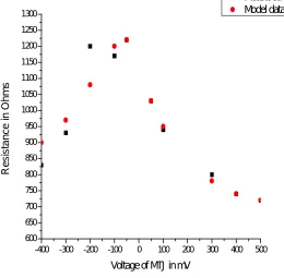
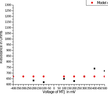
The characteristics curves of resistance versus voltage are shown in Fig: 1 which is characterized in our study. In the figure it is clear that the decreases in applied voltage result in the increases in MTJ resistance. But the changes are asymmetry in the anti parallel state. Fig: 2 shows the characteristics curve of voltage applied in the MTJ with respect to the resistance in the parallel state. It shows that the variation in resistance is very less when the MTJ voltage is applied in parallel state.
-400 -300 -200 -100 0 100 200 300 400 500 600
600 650 700 750 800 850 900 950 1000 1050 1100 1150 1200 1250 1300
R
e
s
is
ta
n
c
e
i
n
o
h
m
s
Voltage of MTJ in mV
Technology (IJRASET)
-400 -300 -200 -100 0 100 200 300 400 500
600 650 700 750 800 850 900 950 1000 1050 1100 1150 1200 1250 1300 R e s is ta n c e i n O h m s
Voltage of MTJ in mV
Fig. 2 Representation of characteristics curve of measured data in parallel state
-400 -300 -200 -100 0 100 200 300 400 500
600 650 700 750 800 850 900 950 1000 1050 1100 1150 1200 1250 1300 R e s is ta n c e i n O h m s
Voltage of MTJ in mV
[image:5.612.179.439.422.677.2]Measured data Model data
Technology (IJRASET)
-400-350-300-250-200-150-100-50 0 50 100 150 200 250 300350400 450 500 600
650 700 750 800 850 900 950 1000 1050 1100 1150 1200 1250 1300
Measured data Model data
R
e
s
is
ta
n
c
e
i
n
O
h
m
s
Voltage of MTJ in mV
Fig. 4 Representation of characteristics curve of measured data and model data in parallel state
VI. TUNNELMODELCORRELATION
In our correlation, the expression 13 is minimized to some extent when the measured data is correlated with the model data It should be noted that we set RP as the average of the measured P-state resistances. The tunnel model parameters are shown in Table 1. Fig: 3 compare the tunnel model to measured results.
TABLEI
TUNNEL MODEL PARAMETER
S. No Model data value Unit value
1 VHP 144.25 mV
2 VHN 320.90 mV
3 RP 674.10 Ohms
[image:6.612.192.421.93.296.2]4 TMR0 0.849 No unit
Fig: 3 show the comparison of measured data and the model data of voltage of MTJ and the resistance in anti-parallel state whereas Fig: 4 show the comparison of measured data and the model data of voltage of MTJ and the resistance in parallel state.
VII. CONCLUSION
A new type of simple static behaviour of MTJ is presented. We propose and computationally analysis the static behaviour of MTJ. The curve fitting of this model is more accurate to obtain good result.
VIII. ACKNOWLEDGEMENT
The author would like to thank to Department of S.O.S in Electronics for providing the necessary tools and software.
REFERENCES
[1] W F Brinkman. Tunneling Conductance of Asymmetrical Barriers. Journal of Applied Physics, 41(5):1915, 1970.
[2] S. S, Mukherjee and S.K. Kurine,”AStable Spice macro-model for magnetic tunnel junction for application in memory and logic circuits,” Trans. Magn.., vol. 45, 9, pp3260-3268, Sep. 2009.
[3] J.D. Harms, T. Ebrahimi, X. Yao, J. P. Wang, “SPICE macro-model of spin-torque-transfer-operated magnetic tunnel junction,” IEEE Trans. Electron Devices, vol. 57, no. 6, pp. 1425-1430, Jun. 2010.