SEGMENTED FUZZY LOGIC CONTROLLER FOR VEHICLE
FOLLOWING WITH OPTIMISED RULE BASE
1S. PAUL SATHIYAN, 2DR. S. SURESH KUMAR, 3DR. A. IMMANUEL SELVAKUMAR
1Department of Electrical and Electronics Engineering, Karunya University, India
2
Department of Electronics and Communication Engineering, Dr. NGP Institute of Technology, India
3 Department of Electrical and Electronics Engineering, Karunya University, India
E-mail: [email protected]
ABSTRACT
Vehicle automation for rear end collision avoidance during vehicle following is an area of research for the past few decade. For Adaptive cruising of vehicles, various controllers have been developed like PI, PID, Model predictive, Sliding mode control, which depend upon the system mathematical model. Designing such a mathematical model for nonlinear system with multiple parameters may not be easy. A controller which can emulate the behaviour of the human, and mimics their reaction which does not require the mathematical modeling of the system may be of high repute. One such controller is Fuzzy Logic controller (FLC). FLC does not need an exact mathematical representation of the system which is to be controlled. The performance of the FLC depends upon how well the fuzzy rule base is framed. The problem with FLC-based system is that, the number of rules used. The rule increases exponentially with the increase of the number of membership values that involve in the rules. This increase, leads to the rise in the computation time of the controller. However the performance of the FLC system highly relies upon the number of membership values and the rules. The crisp output of the FLC does not depend upon the best rule rather it depends upon the entire rule which gets qualified. In-order to have the best rule fired, Genetic Algorithm (GA) is used to optimise the rule base of FLC. Whenever Genetic Algorithm (GA) is used in real time optimisation of fuzzy rule base, the time for reaching the optimised value, depends upon the population size (number of rules in the fuzzy rule base). Hence for a time crucial application like Adaptive cruise control (ACC), offline tuning of fuzzy rule base is performed. In this paper new approach of segmented / divided fuzzy logic based controller is proposed where all the FLC used in ACC is tuned offline using GA and the performance comparison is made.
Keywords: Adaptive Cruise Control, Fuzzy rule base optimisation, Genetic algorithm, Vehicle following,
1. INTRODUCTION
As the growth of technology in transportation, vehicle industry is moving towards manufacturing of vehicles which are completely / partially automated. The motive of such automation is to improve the safety of the car user by relieving the human drivers of tedious tasks that could distract their attention while driving. Adaptive Cruise control (ACC) is an automated vehicle control system, which is used for assisting the driver in maintaining a desired speed (Velocity control mode-VCM) or following a preceding / lead vehicle at a desired distance (Distance control mode-DCM), avoiding rear end collision [1], [2]. Safe car following is a fundamental requirement when developing an ACC Algorithm. Various control techniques like Proportional, Derivative [2], Sliding mode control [4], explicit model predictive control [5], Quadratic optimal theory [6], Reference model based [7] needs the mathematical modelling of the complete system (vehicle). Designing such a
large change in the rule base of the controller is made. The hitch with the FLC-based system is that, the performance of the controller highly relies upon the number of membership values and the rules [11]. The rule increases exponentially with the increase of the number of membership values that involve in the rules. This increase, leads to the rise in the computation time to determine the crisp output by the controller. The crisp output of the FLC does not depend upon the best rule rather it depends upon the entire rule which gets qualified. In-order to have the best rule fired; Genetic Algorithm (GA) is used to optimise the rule base of FLC. GA is a numerical optimisation technique based upon the mechanics of natural selection. Whenever Genetic Algorithm (GA) is used in real time optimisation of fuzzy rule base, the time for reaching the optimised value, depends upon the population size i.e., number of rules in the fuzzy rule base [12]. Hence for a time crucial application like ACC, offline tuning of fuzzy rule base will help in gaining the advantage of both fuzzy logic and GA. The rules are optimised with a common objective function. In this paper a new approach of Segmented / divided FLC is proposed for a time crucial application like ACC, where the advantage of Fuzzy controller which does not require the mathematical modelling of the system, is used. Also the performance of the controller is improved by optimising the rule base of the controller with GA. Since the time taken by the controller to update its crisp output (in order to make the host vehicle to follow the lead vehicle during Distance Control Mode (DCM)), depends on the number of rules in the rule base of the FLC, the single FLC is divided into several FLCs for reducing the time for determining the crisp value without any performance sacrifice. The crisp value computational time is understood by observing how fast the host vehicle tries to adapt to the speed change of the lead vehicle. The work carried out in [14] and [15] had a single FLC, whose rules are optimised considering a common objective function. For ACC application at low speed, comfort can be given highest priority with a little room for distance error and at higher speeds maintaining safer distance has the highest priority than comfort level of the passenger in the vehicle. In the proposed method, each segmented FLC can have their individual objective function, which adds to the performance improvement of the controller. For validating the proposed control technique, a vehicle model proposed by Khairuddin Osman et. al, is adopted. The rest of the paper is organised as follows: Adaptive Cruise control, Vehicle dynamic
modelling, Controller for ACC, Simulation results and Conclusion.
2. ADAPTIVE CRISE CONTROL
[image:2.612.317.515.209.269.2]Driver assistance system for helping the drivers has opened the way for vehicle automation. In particular, drivers must constantly assess the distance and relative speed of vehicles in front and adjust their vehicle speed accordingly.
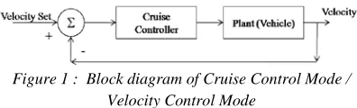
Figure 1 : Block diagram of Cruise Control Mode / Velocity Control Mode
A Cruise Control (CC) system has been developed (Figure 1) to assist the driver for maintaining a set speed and where by reducing the effort of applying constant pressure on the accelerator by the driver during long and continuous travel. This mode of operation is called Velocity control mode (VCM). The system fails when a vehicle is present in the same lane of the vehicle.
Figure2: Block diagram of Adaptive Cruise Control
Figure 3: Inter vehicle distance
Adaptive Cruise Control (ACC) supports the driver in following the lead vehicle at a safer distance avoiding rear end collision (Figure 2). ACC automatically adjusts the host vehicle velocity in order to maintain a safe distance between the two vehicles. This mode of operation is called as Distance Control mode (DCM). Figure 3 shows the inter vehicle distance between the lead and the host vehicle. Speed error, distance error, relative velocity and rate of change of error are primarily considered as the input variables over which the control variables throttle or brake is decided.
Xerror = Xactual – Xdesired (1) Xdesired = Xsafe + THW x Vhost (2) Serror = Slead – Shost (3) Slead = Shost + Xerror x 3.6 (4) Xerror – Distance error
Serror – Speed of the Host vehicle in (km/hr) Slead – Speed of the Lead vehicle in (km/hr) Xsafe – minimum distance of safety in meters Xactual – Actual distance between the vehicles in meters
THW – Time headway
3. VEHICLE DYNAMIC MODELLING
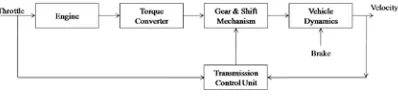
[image:3.612.94.293.273.321.2]For the purpose of comparing the proposed methodology with the conventional single FLC, a vehicle model (plant) has been created whose basic block diagram is shown in Figure 4. The cruise controller regulates the velocity v, of the vehicle as per the drivers’ requirement by adjusting the throttle valve angle u and the brake torque.
Figure 4: Basic drive train system
The moment of inertia or the motion of the car is given by
𝑚𝑑𝑣𝑑𝑡 = F – Fdisturbance (5)
Where F is the force generated by the engine and
Fdisturbanceis the total disturbing force due to gravity,
friction and aerodynamic drag. The force generated by the engine F, whose torque is proportional to throttle position which is determined by the control signal u (0< u< 1) as well as the engine speed ω. The torque at full throttle is given by
𝑇(ω) = Tm�1−β�
ω
ωm−1�
2
�R (6)
Where, the maximum torque Tm is obtained at
engine speed ωm. Let n be the gear ratio and r be
the wheel radius. The relation between the engine speed and the velocity is given by
ω =𝑛𝑟𝑣 (7)
Therefore
𝐹=𝑛𝑣𝑟 𝑇(ω) (8)
The disturbance force is the summation of the force due to gravity Fg, the rolling friction Fr and aerodynamic drag Fa.
𝐹𝑔=𝑚𝑔𝑠𝑖𝑛(θ ) (9)
Where g is the gravitational force (9.81m/s2) and θ is the slope of the road.
𝐹𝑟=𝑚𝑔𝐶𝑟𝑠𝑖𝑛(𝑣 ) (10)
where Cr is the coefficient of rolling friction.
𝐹𝑎=12ρ𝐶𝑑𝐴𝑣2 (11)
Therefore
𝐹𝑑𝑖𝑠𝑡𝑢𝑟𝑏𝑎𝑛𝑐𝑒 = 𝑚𝑔𝑠𝑖𝑛(θ ) +
𝑚𝑔𝐶𝑟𝑠𝑖𝑛(𝑣 ) + 12ρ𝐶𝑑𝐴𝑣2 (12)
The above equations are modelled in Matlab simulink with the following parameters (Annexure 1)
Tm = 190Nm, ωm = 4000rpm β= 0.4, Cr = 0.01, ρ
= air density (1.3k/m3), Cd= 0.32, A=2.4m2
4. CONTROLLER FOR VEHICLE
FOLLOWING
4.1 Fuzzy Logic Controller
Fuzzy controller is suitable for multi-parameters and non linear control problems. Fuzzy theory is a powerful tool in the exploration of complex problems because of its ability to determine outputs for a given set of inputs without using conventional mathematical model. It is developed with the human expertise and knowledge. Fuzziness describes event ambiguity. Fuzzy controller maps the input (a1,a2,....,an) ε ||An
to outputs(y1,y2,....,ym) ε ||A m
. FLC consists of fuzzification method, rule base, inference engine and defuzzification method. Centre of gravity method is used for defuzzification process. The output is given by the formula
Yout=ΣΣiwiai
iwi (13)
Where wi represents the value of the
weight of each rule i and ai is the crisp value of
each rule i condition, understanding weight as the degree in which the crisp current values of the inputs satisfy the set of rule condition. The decision of the FLC depends upon the rule base formed using “IF-THEN” rules. The strength of the FLC depends upon how efficiently the rule base is defined, the number of linguistic variables, type of the membership functions and the range of the fuzzy membership functions. If the number of fuzzy rules and the number of fuzzy linguistic variables are excessive then it will lead to increase in the search time and hence the computational time [13].
4.2 Design of Fuzzy Logic Controller for Vehicle Following
two sided single output (negative side for brake and positive side for acceleration) fuzzy controller with a triangular membership function is selected. Mamdani’s fuzzy inference method is applied. The inputs are defined in equations (1) and (3). Each linguistic variable contain seven membership values as follows.
NL : Negative large NM : Negative medium NS : Negative small
Z : Zero
PS : Positive small PM : Positive medium PL : Positive large
Nine membership values are selected for the output, which includes NVL (negative very large) and PVL (positive very large) apart from the above seven.
The ranges of the linguistic values are as follows Input linguistic variable
1. Distance Error (m):-8< Xerror < 8 2. Relative speed (km/hr):-15<Serror< 15 Output linguistic variable
Throttle / brake command (T/B)
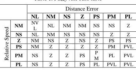
[image:4.612.85.303.441.560.2]The final output of the FLC will be the average of all the outputs. 42 rules proposed by Worrawut et. al [2], for distance control mode, is taken for performance comparison.
Table 1. Fuzzy rule base table
Distance Error
NL NM NS Z PS PM PL
R
el
at
iv
e S
p
eed
NM NV
L NL NM NM NS NS Z
NS NL NM NS NS NS Z Z
Z NM NS Z NS Z PS PS
PS NM Z Z Z Z PM PVL
PM NS Z Z PS P
M PL PVL
PL NS Z Z PS PL PVL PVL
4.3 Optimised Fuzzy Rule Base Using Genetic Algorithm
Optimising fuzzy rule base have been a bottle neck problem in designing fuzzy controller [11]. Neural Network based rule base optimisation has good ability to learn and obtain expected result through training; it takes longer time to learn because of its distributed knowledge and difficulty in understanding the control rules. GA is a combinatorial optimiser that is domain independent and requires a means of representing possible solutions and an objective function evaluator which maps the domain of possible solutions to a scalar value [14], [15]. Also it does not require derivative and other calculations and only depends on
objective function and respective genetic operators which influence the seeking process. Because of the advantage of better searching, coding, decoding, easier implementation of crossover, mutation etc., binary code is adopted. The values {NVL, NL, NM, NS, Z, PS, PM, PL, PVL} of the variable is coded using 4 bit binary as 0000, 0001,0010, 0011, 0100, 0101, 0110, 0111, 1000, 1001. If distance error is NL and relative velocity is Z then the output is NM, the same is encoded as 0001 0100 0010. Thus the binary coded fuzzy rule set is formed. The quality and the number of seed of the original population have a greater influence in the complexity of GA and its convergence status. For tuning the rule base of ACC, the population is taken as 25. Each individual in the initial population consists of a rule. A compact rule base from the initial population is developed from the parent individual. The selection is made with the help of the objective function. Based upon the objective function, GA determines the survival of the individuals in the population. The prime goal of the ACC is to follow the preceding vehicle without collision (minimum distance error and relative velocity) (14). Hence if an individual has to survive, then the resultant has to be minimum.
Xerror(k) 0, Serror(k) 0 (14)
The crossing over operation and the mutation are very important in producing the new individuals. They determine the global and local convergence ability of GA. The crossover probability is taken as 0.7 and the mutation rate is taken as 0.001. Optimised fuzzy rule base is given in table 2, The number of rules is reduced from 49 to 27.
Table 2. Optimised Fuzzy rule base table
Distance Error
NL NM NS Z PS PM PL
R
el
at
iv
e
S
p
eed
NM X X NS NS NM NS NS
NS X NM NS Z Z Z X
Z X NS X NS PS PS PS
PS NM PM PS Z PS PM X
PM X PS PM PS Z PL X
PL X PM X X X X X
4.4 Segmented FLC with optimised rule base
Figure 6: Block diagram of Segmented FLC
Instead of having a conventional single FLC (Figure 5) with maximum rule base size, the single FLC can be divided into several FLCs (Figure 6) based upon the error range, i.e., Error range 1< Error range 2 < Error range 3< . . . <Error range n. Hence FLC1 will deal with the set of rules that operates for the Error range 1, FLC2 will deal with the set of rules that operates for the Error range 2 and FLC3 will deal with the set of rules that operates for the Error range 3. For example, if there are 100 rules in the fuzzy rule base, then the search time will be more when compared to the controller with less than 100 rules. To reduce the search time, the 100 rules available can be divided into a group of rules depending upon the range of error which they are going to respond. These divided rules are loaded into separate FLCs (FLC1, FLC2, …FLCn). These FLCs are given the error input through the Error Range Segmentation, which has an upper and lower limit. The Segmented FLCs (Figure 6) are designed in such a way that FLC1deals with the lowest possible error and FLC3 deals with the maximum possible error. If the error between the reference signal and the feedback signal lies in the range of Error range 2, then FLC2 alone will respond, giving out the necessary firing signal, whereas the other FLC, do not respond. As the error minimizes and comes in the range of Error range 1, FLC1 will start to respond. Hence the search time is reduced, which in turn quickens the response of the controller (host vehicle tries to quickly adapt the changes made by the lead vehicle with more accuracy). Also when the single FLC is divided / segmented into several FLCs, it gives the flexibility to have different objective functions with different minisation and maximisation values for each FLC rule base which may not be the case with the single FLC. At low speed the priority can be given for comfort of the passenger (jerk minimisation). At higher speeds maintaining safer distance is given higher priority than the comfort of the passenger.
5. SIMULATION
The simulation is performed with the vehicle model described in section 3. The performance of conventional FLC, FLC with optimised rule base and the segmented FLC with optimised rule base for the following scenarios are considered.
• Vehicle Following
o Different inter-vehicle distance
o Different rate of acceleration and deceleration.
• Mode Switching period
o Cut in scenario (VCM to DCM)
[image:5.612.325.518.171.362.2]o Cut out scenario (DCM to VCM)
Figure 7: Inter-vehicle Distance
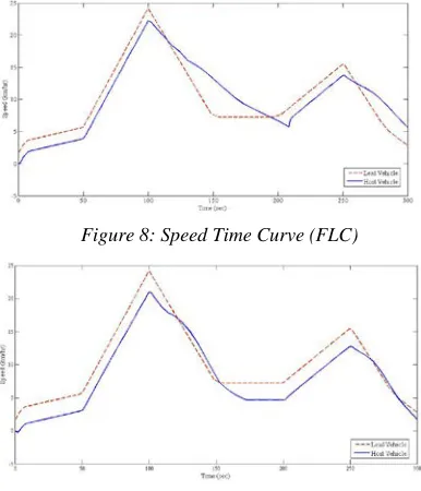
[image:5.612.317.510.487.712.2]Figure 7 shows the inter-vehicle distance maintained between the lead and the host vehicle. The distance varied from 0 to 13 meters. The acceleration and the deceleration rate were changed. The speed graph was plotted between the Lead vehicle speed (expected speed) and the host vehicle speed. The rule base mentioned in table no. 1 is loaded in the FLC for controlling the vehicle. Figure 8 show the response of the vehicle controlled using FLC with 42 rules.
Figure 8: Speed Time Curve (FLC)
The FLC is loaded with the optimised rule base mentioned in table 2. The speed response of the vehicle is shown in Figure 9. The vehicle adapts more closely to the speed variation of the lead vehicle particularly during the time of deceleration period. The performance of the system is improved by segmenting / dividing the error range into 3 different range and simulation is performed. The speed response of the vehicle with the Segmented FLC with optimised rule base is shown in Figure 10.
Figure10: Speed Time Curve (Segmented FLC with optimised rule base)
[image:6.612.94.289.213.330.2]The host vehicle updates itself little earlier than the previous and more accurately follows the lead vehicle.
Figure 11: Inter-vehicle distance
When the inter-vehicle distance range was changed from (0-13) meters to (0-25) meters as the speed range of travel of the vehicle changed from (0-30) Km/hr to (0-80) Km/hr, the FLC explained in section 4.3, was able to control the vehicle in the speed range from (0-25) km/hr and was not able to control the host vehicle to follow the lead vehicle above the range. The speed response of the vehicle is shown in Figure 12 for the inter-vehicle distance shown in Figure 11.
Figure12: Speed Time Curve (FLC with optimised rule base)
[image:6.612.319.522.267.378.2]In order to make the controller work for extended range of operation without increase in the computational time and to achieve the advantage of GA optimisation, the optimised Segmented FLC is proposed, where the error is divided into three different ranges and the rule base was first formed by the knowledge base and then optimised using GA. The error range was segmented / divided based upon the comfort, ability to follow the lead vehicle and safety (maintaining safer distance) of the occupant in the vehicle. The speed response of the Segmented FLC with optimised rule base is shown in Figure 13. The host vehicle was able to follow the lead vehicle.
Figure 13: Speed Time Curve (Segmented FLC with optimised rule base)
The behaviour of the vehicle with the proposed controller is also validated for the mode switching period (cut-in scenario and cut out scenario). Cut-in scenario happens when the lead vehicle speed is less than the driver’s set speed on the host vehicle. The ACC goes into vehicle following mode and adaptively adjust the speed of the host vehicle to follow the lead vehicle with a desired distance (DCM). Cut-out scenario is when the lead vehicle speed is greater than driver’s set speed on the host vehicle. The host vehicle travels at the speed set by the driver. The ACC goes into VCM. The driver’s set speed is taken as a) 25km/hr, b) 50km/hr, c) 60km/hr for observing the behaviour of the vehicle with the proposed controller. The speed response of the host vehicle is plotted Figure 14 (a), 14 (b) and 14 (c), with respect to the lead vehicle speed for the three different set speeds 25km/hr, 50km/hr, 60km/hr respectively.
[image:6.612.95.292.379.495.2]Figure 14 (b): Speed Time Curve (for cruise speed 50Km/hr)
Figure 14 (c): Speed Time Curve (for cruise speed 60Km/hr)
6. CONCLUSION
The performance of the proposed methodology is validated with the conventional fuzzy logic controller and with the rule base optimised single fuzzy logic controller. The proposed methodology shows an improved performance while vehicle following and during switching of ACC between VCM and DCM. Also the speed range of the vehicle is extended with the proposed method without sacrificing the advantage of fuzzy, genetic algorithm optimization and with the reduction in the computational time of the controller whereby closely following the changes made by the lead vehicle. The rule base optimization using GA was greatly influenced by the quality and the number of seed of the original population, iteration and how well the rules are framed. The rules framed can also be optimised with the help of other optimisation algorithms and further there is a possibility in getting a better result. The segmentation is carried based upon the error range which may also be done based upon the level of comfort and safety of the passenger. The proposed methodology is under the process of hardware realisation using dSPACE controller. Multiple parameters like jerks, fuel minimisation, ete., is considered for future work.
REFRENCES:
[1]. Rudwan Abdullah, Amir Hussain, Kevin Warwick, Ali Zayed “Autonomous intelligent cruise control using a novel multiple-controller framework incorporating fuzzy-logic-based switching and tuning”, Neurocomputing – Elsevier, Vol. 17, No 13 – 15, 2008, pp 2727 – 2741
[2]. Worrawut Pananurak, Somphong Thanok, Manukid Parnichkun “Adaptive Cruise Control for an Intelligent Vehicle” Proceedings of the 2008 IEEE International Conference on Robotics and Biomimetics, 2009, pp 1794-1799
[3]. José E. Naranjo, Carlos González,, Jesús Reviejo, Ricardo García, and Teresa de Pedro “Adaptive Fuzzy Control for Inter-Vehicle Gap Keeping” IEEE Transactions On Intelligent Transportation Systems, Vol. 4, No. 3, 2003, pp 132-142.
[4]. Antonella Ferrara, Claudio Vecchio “Second order sliding mode control of vehicles with distributed collision avoidance capabilities”,
Mechatronics, Elsevier, Vol 19, No 4, 2008, pp 471 – 477
[5]. Gerrit Naus, Roel van den Bleek, Jeroen Ploeg, Bart Scheepers, Rene van de Molengraft, Maarten Steinbuch “Explicit MPC Design and Evaluation of an ACC Stop & Go” American
Control Conference, Washington, USA, 2008,
pp 225 – 229
[6]. Li Bin Wang Rongben Chu Jiangwei, “A New Optimal Controller for Intelligent Vehicle Headway Distance” Intelligent Vehicle Symposium,IEEE, Vol 2, 2002, pp 387-392. [7]. John-Jairo Martinez and Carlos
Canudas-de-Wit “A Safe Longitudinal Control for Adaptive Cruise Control and Stop-and-Go Scenarios”
IEEE Transactions On Control Systems Technology, Vol. 15, No. 2, 2007, pp 246 -258 [8]. Sang-Jin Ko and Ju-Jang Lee “Fuzzy Logic
Based Adaptive Cruise Control with Guaranteed String Stability” International Conference on Control, Automation and Systems, 2007, pp 15–20
[10].Kwang So Chang, Jae Sung Choi, “Automatic Vehicle Following using the Fuzzy Logic”,
Proceedings in vehicle navigation and
information system conference, 1995, pp 206-213
[11].Jing Yuan Zhang and YeDe Li “Application of Genetic Algorithm in Optimisation of Fuzzy Control Rules”, Proceedings of the Sixth International Conference on Intelligent
Systems Design and Applications, Vol 1,
2006, pp 529- 534
[12].Jassbi S. Khanmohammadi Kharrati “A New Hybrid Method for Determination of Fuzzy rules & Membership Functions” IEEE Congress on Evolutionary Computation, 2008, pp 1649 -1654
[13].Robert J. Streifel, Robert J. Marks, II, Russell Reed,Jai J. Choi, and Michael Healy, “Dynamic Fuzzy Control of Genetic Algorithm Parameter Coding”, IEEE transactions on systems, man, and
cybernetics—Part B: Cybernetics, Vol. 29,
No. 3, 1999, pp 426 - 433
[14].Mukesh Kumar, Ajay Jangra and Chander Diwaker, “Genetic optimisation of fuzzy rule-base system” International Journal of Information Technology and Knowledge Management, Vol. 2, No. 2, 2010, pp. 287-29 [15].Paul Sathiyan S, A. Wisemin Lins and Dr. S.
ANNEXURE - 1
Matlab Simulink Model Of The Vehicle
1 V ehi cle V el oc ity T ot al F or ce1 T ot al F or ce T ot al E xt . For ces T or que In 1 O ut 1 T hro ttl e Ve l O ut put to W or kspac e V ar iabl e " V el " T ime O ut put to W or kspac e V ar iabl e " T im e" T hro ttl e O ut put to W or kspac e V ar iabl e " T hot tle" O m ega u[1 ]/m N ew ton' s S ec ond Law 5 M ax H ill S lope1 -K -M ax H ill S lo pe H ill E nc ount er H ill C ont rol G rav itat ional F or ces m *g Gr av . C on st. -C -G ear R at io sin( u[ 1] ) Fc n1 f(u ) Fc n E ngi ne F or ce f(u ) D
rag and F