PDP-15
MACRO-15 ASSEMBLER
PROGRAMMER'S REFERENCE MANUAL
1st Printing October 1969
Copyright
©
1969 by Digital Equipment CorporationThe following are registered trademarks of Digital Equipment Corporation, Maynard, Massachusetts:
DEC FLIP CHIP
CHAPTER 1 INTRODUCTION
1.1 1.2 1.3
Macro-15 Language
Hardware Requirements and Options Assemb ler Processi ng
CONTENTS
CHAPTER 2 ASSEMBLY LANGUAGE ELEMENTS
2.1 2.2 2.2.1 2.2.2 2.2.3 2.2.4 2.2.5 2.3 2.3.1 2.3.2 2.4 2.4.1 2.4.2 2.4.3 2.4.4 2.5 2.5.1 2.5.2 2.5.3
2
5.4 2.6 2.6.1 2.6.2 2.6.3 2.6.4Program Statements Symbols
Evaluation of Symbols Variables
Setting Storage Locations to Zero Direct Assignment Statements Undefined Symbols
Numbers Integer Values Express i on s
Address Assignments
Referencing the Location Counter Indirect Addressing
Indexed Addressing Literals
Statement Fields Label Field Operation Field Address Field Comments Fie Id Statement Evaluation Numbers
Word Evaluation
Word Evaluation of the Special Cases Assembler Priority List
CHAPTER 3 PSEUDO OPERATIONS 3.1 Program Identification (. TITLE)
3.2 3.2.1 3.2.2 3.3 3.4
3
.
5
3.6 3.73.8
3.B.1 3.B.23.B.3
3.B.4
3.B.5
3.9 3.103.11
3.12 3.13 3.143.15
3.16Object Program Output .ABSP, .ABS
.FULL, .FULLP Pseudo-ops
CONTENTS (Cont)
Sett ing the Location Counter ( . .LOC) Radix Control (.OCT and .DEC) Reserving Blocks of Storage (. BLOCK) Program Termination (. END)
Program Segments (. EOT)
Text Handling (.ASCII and. SIXBT) . ASCII Pseudo-op
. SIXBT Pseudo-op T ext Statement Format Text Delimiter
Non-Printing Characters Loader Control (. G LOBL)
Requesting I/O Devices (.IODEV) Defining a Symbolic Address (.DSA) Repeating Object Coding (. REPT)
Conditional Assembly (.IF xxx and .ENDC) Listing Control (.EJECT)
Program Size (. SIZE)
Defining Macros (.DEFIN, .ETC, and .ENDM)
CHAPTER
4
MACROS 4.14.2 4.3 4.3.1 4.3.2
4.4
4.54.6
4.7
Defining a Macro Macro Body Macro Calls
Argument Delimiters Created Symbol s
Nesting of Macros Redefinition of Macros
Macro Calls Within Macro Definitions Recursive Ca lis
CONTENTS (Cont)
CHAPTER 5 OPERATING PROCEDURES
5. 1
5.2
5.3
5.4
5.4.1
5.4.2
5.5
5.6
5.7
5.7.1
5.7.2
5.8
5.9
5.9.1
5.10
Introduction
Calling Procedure
General Command Characters
Command String
Program Name
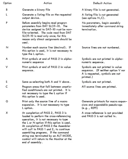
Options
Assembly Listings
Symbol Table Output
Running Instructions
Paper Tape Input Only
Cross-Reference Output
Program Relocation
Error Conditions and Recovery Procedures
Restart Control Entries
Error Detection
APPENDIX A CHARACTER SET
APPENDIX B PERMANENT SYMBOL TABLE
APPENDIX C MACRO-15 CHARACTER INTERPRETATION
APPENDIX D SUMMARY OF MACRO-9 PSEUDO-OPS
APPENDIX E SUMMARY OF SYSTEM MACROS
APPENDIX F SOURCE LISTING OF THE ABSOLUTE BINARY LOADER
APPENDIX G SYMBOL TABLE SIZES
Page
PREFACE
OVERALL PDP-15 DOCUMENTATION STRUCTURE
A tree-type block diagram of the overall "PDP-15 Fami Iy of Manuals" is illustrated on page vii i. A brief description of the contents and the order number of each manual shown in the diagram are presented on page ix.
ORGANIZATION OF PDP-15 SOFTWARE MANUALS
There are two basic catagories of PDP-15 software manuals:
a. Unique, single-system, manuals which contain information concerning only one of the four available PDP-15 systems. This catagory consists of detai led software system descriptive manuals, each with an associated op-erational command summary. An example of this class of manual would be the "PDP-15/10 Software System" manual and its associated "PDP-15/10 Users· Guide".
~.
INSTALLATION MANUAL
MODULE MANUAL
HARDWARE
ACCEPTANCE TE ST PROCEDURES
INTERFACE MANUAL
PDP-15 FAMILY OF MANUALS
OPERATORS GUIDE
SOFTWARE
PDP-15/40 PDP-15/30 PDP-15/20 PDP-15 110
SYSTEM USER'S 1-1.1-' --+~
GUIDE
MACRO -15
FOCAL-15
UTILITY PROGRAMS
MANUAL
PDP-15/40 PDP-15/30 PDP-15/20 PDP-15/10
SOFTWARE SYSTEM
FORTRAN TIL
8 115 TRANSLATOR
SYSTEM REFERENCE MANUAL - Overview of PDP-15 hardware and software systems and options; instruction repertoire, expansion features and de-scriptions of system peripherals.
DEC-15-GRZA-D
USERS GUIDE VOLUME I, PROCESSOR - Principal guide to system hardware includes system and subsys-tem features, functional descriptions, machine-language programming considerations, instruction repertoire and system expansion data.
DEC-15-H2DA-D
VOLUME 2 PERIPHERALS - Features functional de-scriptions and programming considerations for periph-eral devices.
DEC-15-H2DA-D
OPERATOR'S GUIDE - Procedural data, including operator maintenance, for using the operator's con-sole and the peripheral devices associated with
PDP-15 Systems.
DEC-15-H2CA-D
PDP-15/1O SYSTEM USER'S GUIDE - COMPACT and BASIC
I/o
Monitor operating procedures.DEC-15-GG IA-D
PDP-15/20 SYSTEM USER'S GUIDE - Advanced monitor system operating procedures.
DEC-15-MG2A-D
PDP-15/30 SYSTEM USER'S GUIDE - Background/ Foreground monitor system operating procedures.
DEC-15-MG3A-D
PDP-15/40 SYSTEM USER'S GUIDE - Disk-oriented background/foreground monitor system operating procedures.
DEC-15-MG4A-D
PDP-15/10 SOFTWARE SYSTEM - COMPACT soft-ware system and BASIC
I/o
Monitor system descrip-tions.DEC-15-GRIA-D
PDP15/20 ADVANCED Monitor Software System -ADVANCED Monitor System descriptions; programs include system monitor and language, utility and application types; operation, core organization and
input/output operations within the monitor environ-ment are di scussed .
DEC -15-MR2A-D
PDP-15/30 BACKGROUND/FOREGROUND Monitor Software System - Background/Foreground Monitor description including the associated language, util-ity and appl ications programs.
DEC-15-MR3A-D
PDP-15/40 Disk-Oriented BACKGROUND/ FORE-GROUND Monitor Software System - Background/ Foreground Mo,":',x in a disk-oriented environment is described; programs include language, utility, and appl ication types.
DEC -15-MR4A-D
MAINTENANCE MANUAL VOLUME I, PROCES-SOR - Block diagram and functional theory of op-eration of the processor logic. Preventive and cor-rective maintenance data.
DEC-15-HB2A-D
VOLUME 2, PROCESSOR OPTIONS - Block dia-gram and functional theory of operation of the processor options. Preventive and corrective main-tenance data.
DEC-IS-HB2A-D
VOLUME 3 PERIPHERALS (Set of Manuals) - Block diagram and functional theory of operation of the peripheral devi ces. Preventive and corrective maintenance data.
DEC-15-HB2A-D
INSTALLATION MANUAL - Power specifications, environmental considerations, cabl i ng and other information pertinent to installing PDP-15 Systems.
DEC-15-H2AA-D
ACC EPT ANCE TEST PROC EDURES - Step-by-step procedures designed to insure optimum PDP-IS Sys-tems operation.
MODULE MANUAL - Characteristics, specifica-tions, timing and functional descriptions of mod-ules used in PDP-15 Systems.
INTERFACE MANUAL - Information for interfacing devices to a PDP-15 System.
DEC-1S-HOAA-D
UTILITY PROGRAMS MANUAL - Utility programs common to PD P-1S Monitor systems.
DEC-1S-YWZA-D
MACRO-15 - Ml i~O assembly language for the PDP-15.
DEC-IS-AMZA-D
FORTRAN IV - PDP-15 version of the FORTRAN IV compi ler language.
DEC-1S-KFZA-D
FOCAL-IS - An algebraic interactive compiler-level language developed by Digital Equipment Corporation.
1.1 MACRO-15 LANGUAGE
CHAPTER 1
I NTRODUCTIO N
MACRO-15 is a basic PDP-15 symbolic assembler language which makes machine language programming on the
PDP-15 easier, faster and more efficient. It permits the programmer to use mnemonic symbols to represent
in-struction operation codes, locations, and numeric quantities. By using symbols to identify inin-structions and data
in his program, the programmer can easily refer to any point in his program, without knowing actual machine
locations.
Assembled MACRO-15 programs may be run on any PDP-15 system; however, MACRO-15 symbolic programs can
be assembled only on systems which have at least 8K of memory and a monitor-type software system.
The standard output of the Assembler is a relocatable binary object program that can be loaded for debugging or
execution by the Linking Loader. MACRO-15 prepares the object program for relocation, and the Linking
Loader sets up linkages to external subroutines. Optionally, the binary program may be output either with
ab-solute addresses (non-relocatable) or in the full binary mode (see Chapter 3 for a description of the binary out-put modes).
The programmer directs MACRO-15 processing by using a powerful set of pseudo-operation (pseudo-op)
instruc-tions. These pseudo-ops are used to set the radix for numerical interpretation by the Assembler, to reserve
blocks of storage locations, to repeat object code, to handle strings of text characters in 7-bit ASCII code or a
special 6-bit code, to assemble certain coding elements if specific conditions are met, and to perform other
functions which are explained in detail in Chapter 3.
The most advanced features of MACRO-15 is its powerful macro instruction generator. This generator permits
easy handling of recursive instruction sequences, changing only the arguments. Programmers can use macro
in-structions to create new language elements, adapting the Assembler to their specific programming applications.
Macro instructions may be called up to three levels, nested to ~ levels, and redefined within theprogram. The
An output listing, showing both the programmer's source coding and the object program produced by MACRO-15,
is printed if desired. This listing includes all the symbols used by the programmer with their assigned values. If
assembly errors are detected, erroneous lines are marked with specific letter error codes, which may be inter-preted by referring to the error list in Chapter 5 of this manual.
Operating procedures for MACRO assembly are described in detail in Chapter 5. These procedures are also summarized in the "Users' Guide" for each Monitor Software system.
1.2 HARDWARE REQUIREMENTS AND OPTIONS
The MACRO-15 assembler program may be run on any of the following PDP-15 systems:
a. 15/10 system which has a minimum of 8K of core and optional high-speed paper tape reader and'
punch units.
b. basic 15/20 system c. basic 15/30 system d. basic 15/40 system
1.3 ASSEMBLER PROCESSING
The MACRO-1S assembler processes source programs in either a pass or three-pass operation. In the two-pass assembly operation the source program is read twice with the object program (and printed listing when
re-quested) being produced during the second pass. During the first pass (PASS 1), the locations to be assigned the program symbols are resolved and a symbol table is constructed by the assembler. The second pass (PASS 2) uses the information computed during PASS 1 to produce the final object program.
In an optional three-pass assembly operation, PASS 2 will call in a third pass (PASS 3) portion of the assembler program. PASS 3, when called, performs a cross referencing operation during which a listing is produced which
contains: (a) al/ user symbols, (b) where each symbol is defined, and (c) the number of each program line in which a symbol is referenced. On completion of its operation, PASS 3 calls the PASS 1 and PASS 2 portions of the assembler program back into core for further assembly operations.
The standard object code produced by MACRO-15 is in a relocatable format which is acceptable to the PDP-15 Linking Loader Utility program. Relocatable programs that are assembled separately and use identical global symbols* where applicable, can be combined by the Linking Loader into an executable object program.
MACRO-15 reserves one additional word in a program for every external** symbol. This additional word is used
as a pointer to the actual data word in another program. The Linking Loader sets up these pointers when the programs are loaded.
*Symbols which are referenced in one program and defined in another.
Some of the advantages of having programs in relocatable format are as follows:
a. Reassembly of one program, which at object time was combined with other programs, does not necessitate a reassembly of the entire system.
b. Library routines {in relocatable object code} can be requested from the system device or user library device.
2.1 PROGRAM STATEMENTS
CHAPTER 2 ASSEMBLY LANGUAGE ELEMENTS
Asingle statement may be written on a 72-character Teletype line, in which case the carriage-return line-feed sequence characters delimit the statement. Such a statement actually begins with a line-feed character and is terminated by a carriage-return character. Since these form-control characters are not printed, they are repre-sented as) (carriage return) and I (line feed). In the examples of statements in this manual, only the carriage return is shown:
STATEMENT)
Several statements may be written on a single line, separated by semicolons:
STATEMENT;STATEMENT;STATEMENT )
In this case, the statement line begins with a line-feed character and ends with a carriage-return character, but semicolons are used as internal statement delimiters. Thus, if a statement is followed by another statement on the same line, it ends with a semicolon.
A statement may contain up to four fields that are separated by a space, spaces, or a tab character. These four fie kls are the labe I (or tag) fie Id, the operation field, the address field, and the comments field. Because the space and tab characters are not printed, the space is represented by ~ , and the tab by -l in this manual. Tabs are set 10 spaces apart on most Teletype machines, and are used to line up the fields in columns in the source program Ii sti ng.
This is the basic statement format:
LABEL -l OPERATION
-I ADDRESS -l/COMMENTS)
Note that a combination of a space and a tab will be interpreted by the MACRO-15 assembler as two field
delimiters.
Example:
TAG -lOP L....I
-I
ADR) TAG L....I-I
OP-I
ADR)J
both are incorrect
These errors will not show on the listing because the space is hidden in the tab.
A MACRO-15 statement may have an entry in each of the four fields, or three, or two, or only one field. The fo Ilowi ng forms are acceptab Ie:
TAG)
TAG
-I
OP)TAG
-I
OP-I
/\DDR)TAG
-lop -l
ADDRL....I (s} / comments) TAG-I
OPL....I (s) / comments)TAG
-l -l
ADDR)TAG
-l
-I
ADDR L....I (s) / comments) TAG-l
(s) / comments)-lop)
-l
OP-I
AD[;R)-I
OP-I
ADDR-l
(s) / comments)-l
OP-
,
I
(s) / comments)-l -l
ADDR)-I
-l
ADDR-l
(s) / comments) /comments)-I
(s) / comments)Note that when a label field is not used, its delimiting tab is written, except for lines containing only comments.
When the operation field is not used, its delimiting tab is written if an address field follows, except in label only and comments only statements.
A label (or tag) is a symbolic address created by the programmer to identify the statement. When a label is
processed by the Assembler, it is said to be defined. A label can be defined only once. The operation code field may contain a machine mnemonic instruction code, a MACRO-15 pseudo-op code, a macro name, a
num-ber, or a symbol. The address field may contain a symbol, numnum-ber, or expression which is evaluated by the
instructions, this field is used for other purposes, as will be explained in this manual. Comments are usually
short explanatory notes which the programmer adds to a statement as an aid in analysis and debugging. Comments
do not affect the object program or assembly processing. They are merely printed in the program listing.
Com-ments must be preceded by a slash (/). The slash (/) may be the first character in a line or may be preceded by:
a. Space ( ... )
b. Tab (
-I )
c. Semicolon (;)
2.2 SYMBOLS
The programmer creates symbo Is for use in statements, to represent addresses, operation codes and numeri c values.
A symbol contains one to six characters from the following set:
The letters A through Z
The dig i ts 0 through 9
Two spec ia I characters, period ( . ) and the percent sign (%).
The first character of a symbol must be a letter, a period, or percent sign. A period may not be used alone as
a symbol. The first character of a symbol must not be a digit.
The following symbols are legal:
MARK1
A%
P9.3
The following symbols are illegal:
TAG:1
5ABC
.. 1234
%50.99
INPUT
L@B1
.A
.%
: and @ are i Ilega I characters.
First character may not be a digit.
Only the first six characters of a symbol are meaningful to the Assembler, but the programmer may use more for
his own information. If he writes,
SYMBOL 1
SYMBOL2
as the symbolic labels on three different statements in his program, the Assembler will recognize only SYMBOL and may type error flags on the lines containing SYMBOL 1, SYMBOL2 and SYMBOL 3. To the Assembler they are duplicates of SYMBOL.
2.2.1 Evaluation of Symbols
When the Assembler encounters a symbol during processing of a source language statement, it evaluates the sym-bol by reference to two tables: the user's symsym-bol table and the permanent symsym-bol table. The user's symsym-bol table contains all symbols defined by the user. The user defines symbols by using them as labels, as variables, as macro names, and by direct assignment statements. A label is defined when first used, and cannot be redefined. (When a label is defined hy the user, it is given the current value of the location counter, as will be explained later in this chapter.)
All permanently defined system symbols, including Monitor commands and all Assembler pseudo-instructions use a period ( . ) as their first character. (In some cases the". " may be used as the last character of a Monitor
I/o
symbol). The Assembler has, in its pHrmanent symbol table, definitions of the symbols for all of the PDP-15 memory reference instructions, operate instructions, EAE instructions, and some input/output transfer instructions. (See Appendix B for a complete list of these instructions.)PDP-15 instruction mnemonic symbols may
be
used in the operation field of a statement without prior definition by the user.Example:
-I
LAC~A) LAC is a symbol whose appearance in the operation field of a statement causes the Assembler to treat it as an op code rather than a symbolic address. It has a value of 2000008 which is taken from the operation
code definition in the permanent symbol table.
The user can use instruction mnemonics or the pseudo-instruction mnemonics code as symbol labels. For example,
DZM
-I
DZM~, Y)with values' have been entered in the user's symbol table and the permane.nt symbol table. The sample coding shows how the Assembler uses these tables to form object program storage words.
User Symbol Table
Symbol Value
TAG1 100
TAG2 200
DAC 300
If the following statements are written,
TAG1 .., DAC .., TAG2
T AG2.., LAC
-I
DACDAC
--.j
JMP--.j
TAG 1 DAC--.j
TAG1,X--.j
TAG 1Permanent Symbol Tab Ie
Symbol Value
LAC 200000
DAC 040000
JMP 600000
X 010000
the following code is generated by the Assembler
040200
200300
600100 050100 000100
2.2.1.1 Special Symbols - The symbol X is used to denote index register usage. It is defined in the permanent symbol table as having the value of 10000. The symbol X cannot be redefined and can only be used in the ad-dress field.
2.2.1.2 Memory Referencing Instruction Format - The PDP-15 uses 12 bits for addressing, 1 bit to indicate index register usage, 1 bit to indicate indirect addressing, and 4 bits for the op code.
0 2 3 4 5 6 7 8 9 10 11 12 13 14 15 16 17
Op Code
I
Address2.2.2 Variables
A variable is a symbol that is defined in the symbol table by using it in an address field or operation field with the number sign (#). Symbols with the # may appear more than once in a program (see items 1,3,4, and 5 of example given below). A variable reserves a single storage word which may be referenced by using the symbol at other points in the program with or without the #. If the variable duplicates a user-defined label, it is mul-tiply defined and is flagged as an error during assembly.
Variables are assigned memory locations at the end of the program. The initial contents of variable locations are unspecified.
Example:
Sequence Location Source Statements Generated
Counter Code
...,
. LOC L..I 1001 100
...,
LAC L..I T A# G 1 2001052 101
...,
DAC L..I TAG3 0401073 102
...,
LAC L..I T AG2# 2001064 103
...,
DAC L..I T# AG3,X 050107 5 104...,
LAC L-I#TAG2 200106...,
.END2.2.3 Setting Storage Locations to Zero Storage words can be set to zero as follows:
In this way, three words are set to zero starting at Z. Storage words can also be set to zero by statements con-taining only labels
A;B;C;D;E)
2.2.4 Direct Assignment Statements
The programmer may define a symbol directly in the symbol table by means of a direct assignment statement, written in the form:
where n is any number or expression. There should be no spaces between the symbol and the equal sign, or
between the equal sign and the assigned value, or symbol. MACRO-15 enters the symbol in the symbol table,
along with the assigned value. Symbols entered in this way may be redefined. These are legal direct assignment
statements:
X=28; A=l: B=2)
A symbol can also be assigned a symbolic value; e.g., A=4, B=A, or
SET=ISZ1....JSWITCH
In the above example, the symbol B is given the value 4, and when the symbol SET is detected during assembly
the object code for the instruction ISZL-ISWITCH will be generated. This type of direct assignment cannot be
used ina re locatable program. Direct assignment statements do not generate storage words in the object program.
In general, it is good programming practice to define symbols before using them in statements which generate
storage words. The Assembler will interpret the following sequence without trouble.
Z=5
Y=Z
X=Y
-.J
LACL-IXL-I/SAME AS LAC 5)A symbol may be defined after use. For example,
LAC Y)
Y=l)
This is called a forward reference, and is resolved properly in PASS 2. When first encountered in PASS 1, the
LAC Y statement is incomplete because Y is not yet defined. Later in PASS 1, Y is given the value 1. In
PASS 2, the Assembler finds that Y = 1 in the symbol table, and forms the complete storage word.
Since MACRO-15 basic assembly operations are performed in two passes, only one-step forward references are
allowed. The following is illegal:
LAC Y)
Y=Z)
Z=I)
2.2.5 Undefi ned Symbo I s
If any symbols, except global symbols, remain undefined at the end of PASS 1 of assembly, they are automatically
defined as the addresses of successive registers following the block reserved for variables at the end of the
pro-gram. All statements that referenced the undefined symbol are flagged as undefined. One memory location is
reserved for each undefined symbol with the initial contents of the reserved location being unspecified.
Examples:
Flag Location Source Statements Generated Comments
Counter Code
-I
. LOC L-I 100)u 100
-I
LAC L-I UNDEF1) 200106 Undefined Symbol101
-I
LAC L-I TAG#) 200104102
-I
LAC L-I TAG# 1) 200105u 103
-I
LAC L-I UND EF2) 200107 Undefined Symbol-I .
END)2.3 NUMBERS
The initial radix (base) used in all number interpretation by the Assembler is octal (base 8). To allow the user
to express decimal values and then restore to octal values, two radix-setting pseudo-ops (. OCT and. DEC) are
provided. These pseudo-ops, described in Chapter 3, must be coded in the operation field of a statement. If
any other information is written in the same statement, the Assembler treats the other information as a comment
and flags it as a questionab Ie line. All numbers are decoded in the current radi x unti I a new radix control
pseudo-op is encountered. The programmer may change the radix at any point in the program.
Examples:
Flag Source Program Generated Value (Octal) Radix in Effect
-I
LAC -1100 200100 8}
initial value is-I
25 000025 8 assumed to be octal-I
.DEC-I
LAC -1100 200144 10-I
275 000423 10Q
-I
.OCT L-I 99 Octal radix takes effect eventhough line is flagged
-I
76 000076 82.3.1 Integer Values
An integer is a string of digits, with or without a leadi ng sign. Negative numbers are represented in two's
complement form. The range of integers is as follows:
Unsigned
Signed
0-262143 10
±Q -131071 10
18 (777777
8) or 2 - 1 17 (377777
8) or
±2 -
1An octal integer* is a string of digits (0-7), signed or unsigned. If a non-octal digit (8 or 9) is encountered
the string of digits will be assembled as if the decimal radix was in effect and it will be flagged as a possible
error.
Example:
Flag Coded Value Generated Value (Octal) Comment
.DEC
3779 007303
.OCT
-5 777773 Two's complement
3347 003347
N 3779 007303 Possible error, decimal
assumed
A decimal integer** is a string of digits (0-9), signed or unsigned.
Examples:
Flag Coded Value Generated Value (Octal) Comment
-8 77mO Two's complement
+256 000400
N -136098 000000 Error, greater than -2 -1 17
2.3.2 Expressions
Expressions are strings of symbols and numbers separated by arithmetic or Boolean operators. Expressions
repre-sent unsigned numeric values ranging from 0 to 218 -1. All arithmetic is performed in unsigned integer arithmetic
(two's complement), modulo 218. Division by zero is regarded as division by one and results in the original
dividend. Fractional remainders are ignored; this condition is not regarded as an error. The value of an
ex-pression is calculated by substituting the numeric values for each element (symbol) of the exex-pression and
per-forming the specified operations.
The following are the allowable operators to be used with expressions:
Character Function
Name Symbol
Plus + Addition (two's complement)
Minus
-
Subtraction (convert to two's complement and add)Asterisk * Multiplication (unsigned)
Slash
/
Division (unsigned)Ampersand & Logical AND
Exc lamation point ! Inclusive OR
}
BooleanBack slash
\
Exclusive ORComma
,
Exclusive OROperations are performed from left to right (i .e., in the order in which they are encountered). For example,
the assembly language statement A+B*C+D/E-F*G is equivalent to the following algebraic expression
(((((A+B)*C)+D)/E)-F)*G.
Examples:
Assume the following symbol values:
Symbol Value (Octal) Comments
A
000002
B
000010
C
000003
D
000005
X
010000
Index Register ValueExpression Evaluation (Octal) Comments
A+B-C,X 010007 Index Register Usage
A/B+A*C 000006 (The remainder of A/B is lost)
B/A-2*A-l+X 010003 Index Register Usage
A&B 000000
C+A&D 000005
B*D/A 000024
B*C/A*D 000074
A,X+D,X 010007 Index Register Usage Error
In the last example the expression is evaluated as follows:
Sequence of arithmetic
a. A,X
=
000002 XORed with 010000=
010002 b. A,X+D=
010002 + 000005=
010007c. A,X+D,X
=
010007 XORed with 010000=
000007Note that arithmetic produces 000007 yet the value given in the example is 010007. Regardless of how the
in-dex register is used in the address field, the inin-dex register bit will always be turned on by the Assembler. In
the sequence of address arithmetic above, the line would be flagged with an X because of the illegal use of the
index register symbol (X).
Using the symbol X to denote index register usage causes the following restrictions:
a. X cannot appear in the TAG field
b. X cannot be used in a . DSA statement
c. X can only be used once in an expression
2.4 ADDRESS ASSIGNMENTS
X
-I
LAC-I
A.DSA A,X
LAC A,X+D,X
As source program statements are processed, the Assembler assigns consecutive memory locations to the storage
words of the object program. This is done by reference to the location counter, which is initially set to zero
and is incremented by one each time a storage word is formed in the object program. Some statements, such as
machine instructions, cause only one storage word to be generated, incrementing the location counter by one.
Other statements, such as those used to enter data or text, or to reserve b locks of storage words, cause the
2.4.1 Referencing the Location Counter
The programmer may directly reference the location counter by using the symbol period ( . ) in the address field. He can wri te ,
~
JMP...,.-l
which will cause the program to jump to the storage word whose address was previously assigned by the location counter. The location counter may be set to another value by using the .LOC pseudo-op, described in Chapter3.
2.4.2 Indirect Addressing
To specify an indirect address, which may be used in memory reference instructions, the programmer writes an asterisk immediately following the operation field symbol. This sets the defer bit (bit 4) of the storage word.
If an asterisk suffixes either a non-memory reference instruction, or appears with a symbol in the address field, an error will resu It .
Two examples of legal indirect addressing follow.
~ TAD*-I A -I LAC*~ B
The following examples are illegal.
CLA* LAW* 17777
2.4.3 Indexed Addressing
Indirect addressing may not be specified in non-memory reference instructions.
To specify indexed addressing an X is used with an operator directly after the address. No spaces or tabs may appear before the operator. The Assembler will perform whatever operation is specified with the index register symbol, and then continue to evaluate the expression. At completion of the expression evaluation, if the index bit is not on and the location counter is pointing to page 0 of any bank, the line is flagged with a B for bank error. The standard code used to indicate indexing is:
Example:
Object Location Code
.ABSP
000000 210000 A LAC
-i
X /Same as LAC 0, X 000001 210005 B DAC~ A,X+l,7-1/
000002 21000 1 LAC B+X /00000 1 010000
. LaC 10000 /SET to page 1
010000 210001 C LAC X,D
010001 210000 D LAC C,X
.END
expression evaluation where A
=
000000, B=
000001, C=
010000, X=
0100002.4.4 Literals
Location
o
2
10000
10001
Address Field
X
A,X+l,7-1
B+X
X,D
C,X
Discussion
The value of X is added to O. Absence of an operator always implies addition.
000000 + 0 1 0000 = 0 10000
o
1 0000 + 000001 = 0 10001o
1 000 1 + 000007 = 010006o
1 0006 - 000001 = 0 10005 00000 1 + 0 10000 = 0 10001o
1 0000 + 0 10001 = 000001The index bit has been turned off during expression evaluation. Because the lo-cation counter (10000) is pointing to page 1, this line is not flagged and the index register bit is turned on.
o
1 0000 + 0 1 0000 = 000000Same as example at location 10000.
NOTE: + = exclusive OR
Symbolic data references in the operation and address fields may be replaced with direct representation of the
data enclosed in parentheses*. This inserted data is called a literal. The Assembler sets up the address link,
so one less statement is needed in the source program. The following examples show how literals may be used,
and their equivalent statements. The information contained within the parentheses, whether a number, symbol,
expression, or machine instruction, is assembled and assigned consecutive memory locations after the locations
used by the program. The address of the generated word will appear in the statement that referenced the literal.
Duplicate literals, completely defined when scanned in the source program during PASS 1, are stored only once so that many uses of the same literal in a given program result in the allocation of only one memory location for that literal.
Usage of Literal Equivalent Statements
-I
ADD I-J,(l)-I
ADDI-J ONEONE
...,
1-l
LAC I-J (TAG)-I
LAC I-J T AGADTAGAD -I TAG
-I
LAC I-J (DAC-I
TAG)-I
LAC ~ INST INST-I
DAC-I
TAG-I
LAC I-J (JMP-I .
+2) HERE-l
LAC I-J INSTINST
-I
JMP I-J HERE+2The following sample program illustrates how the Assembler handles literals.
Location Counter Source Statement Generated Code
-I
. LOC L...I 100100 TAG1-1 LAC L...I (100) 200110
101
-I
DACL...I 100 040100102
-I
LAC I-J (JMP L-.I' • +5 200111103
-I
LAC L...I(TAGl) 200110104
...,
LAC L...I (JMP I-J TAG 1) 200112105
...,
LAC L...I (JMP L...I T AG2) 200113TAG2=TAGl
106
-I
LAC I-J (JMP 0) 200114107 DAC
-I
LAC I-J.(DAC-I
DAC) 200115-I .
ENDGenerated Litera Is
110 000100
111 600107
112 600100
113 600100
114 600000
2.5 STATEMENT FIELDS
The following paragraphs provide a detailed explanation of statement fields, including how symbols and numbers
may be used in each fie I d .
2.5.1 Label Field
If the user wishes to assign a symbolic label to a statement in order to facilitate references to the storage word
generated by the Assembler, he may do so by beginning the source statement with any desired symbol. The
symbol must not duplicate. a system or user defined macro symbol and must be terminated by a space or tab, or a
statement terminating semicolon, or carriage-return/line-feed sequence.
Examples:
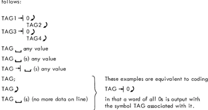
TAG 1 ;TAG2;TAG3;TAG4 A new logical line starts after each semicolon. This line is equivalent to
TAG1-\ 0) TAG2-\ 0) TAG3
--I
0) TAG4--I
0)If there was a tab or a space after the semicolon the symbol would be evaluated as an operator instead of a
tag. The sequence
TAG1;~ TAG2;TAG3;L-.I TAG4
is eva luated as fo Ilows:
TAG1-\0) TAG2 ) TAG3 -\ 0)
TAG4)
T AG ~ any value TAG ~ (s) any va lue TAG -\ ~. (s) any value
TAG;
1
TAG)
TAG ~ (s) (no more data on line)
These examples are equivalent to coding
TAG
--I
0)in that a word of aliOs is output with the symbol TAG associated with it.
When writing numbers separated by semicolons, the first number must be preceded by a tab
(--I )
or a space (~).The sequence
[image:26.618.142.480.460.639.2]produces TAG errors because the first symbol of a tag cannot be numeric. The correct way to write the table sequence is as follows:
TABLE ... li ... 2i ... 3; ... 4; ... ;)
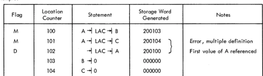
Symbols used as labels are defined in the symbol table with a numerical value equal to the present value of the location counter. A label is defined only once. If it was previously defined by the user, the current definition of the symbol will be flagged in error as a multiple definition. All references to a multiply defined symbol will be converted to the first va lue encountered by the Assembler.
Example:
Flag Location Statement Storage Word Notes
Counter Generated
M 100 A -I LAC-I B 200103
M 101 A -I LAC -I C 200104
J
Error, multiple definition0 102 -I LAC -I A 200100 First value of A referenced
103 B-IO 000000
104 c-Io 000000
Anything more than a single symbol to the left of the label-field delimiter isan error; it will be flagged and ignored. The followi ng statements are i II ega I.
TAG+l -I LAS) LOC*2 -I RAR)
The line will be flagged with a "T" for tag error. The tag will be ignored but the rest of the line will continue to be processed. The on Iy time that an error tag is not ignored is when the error occurs after the sixth character. The statement:
TAGERROR*l ... NOP
will be assembled as:
T AGERR -I NOP
and the line will be printed and flagged with a "T".
[image:27.615.80.531.234.364.2]is redefined, the value of the symbol can be changed without causing an error message. If a user symbol, which
was first defined as a label, is redefined by either a direct assignment or by using it again in the label field, it
will cause an error. Variables also cannot be redefined by a direct assignment.
Examples:
Coding Generated Value (Octal) Comments
A=3 Sets current va lue of A to 3
--l LAC --l A 200003
--l DAC--l A 040003
A=4 Redefines value of A to 4
--l LAC --l A 200004
B --l DAC --l A 040004 *
B=A Illegal usage; a label cannot
be redefined
--l DAC --l B 040 lOS
PSF=700201 To redefi ne possibly incorrect
permanent symbol definition.
*Assume that this instruction will occupy location lOS.
2.S.2 Operation Field
Whether or not a symbol label is associated with the statement, the operation field must be delimited on its left
by a space(s) or tab. If it is not delimited on its left, it will be interpreted as the label field. The operation field may contain any symbol, number, or expression which will be evaluated as an 18-bit quantity using un-signed arithmetic modulo 218. In the operation field, machine instruction op codes and pseudo-op mnemonic
symbols take precedence over identically named user defined symbols. The operation field must be terminated
by one of the following characters:
Examples:
--l or L...I (s)
) or ;
TAG --l ISZ
(field delimiters)
(statement delimiters)
--l . +3 L-I (s) L-I (s)CMA !CML)
--l TAG/S+TAG2; --l TAG3)
The asterisk (*) character appended to a memory reference instruction symbol, in the operation field, causes
the asterisk (*) is appended on either a non-memory reference instruction or any symbol in the address field,
it will cause an error condition which will be flagged as a symbol error (S-flag). The asterisk will be ignored
and the assembly process will continue.
Examples:
Assembled Value Legal Assembled Value Illegal
360001
-.j
TAD*-.j
A 360001-.j
LAC-.j
A*220002
-.j
LAC *-.j
B 740000-.j
CLA*where A = 1 and B
=
2However, the asterisk (*) may be used anwhere as a multiplication operator.
Examples:
Legal Illegal
-.j
LAC-.j
TAG*5-.j
LAC-.j
TAG*4+TAD*-.j
TAG*TAGl-.j
A*2.5.3 Address Field
The address field, if used in a statement, must be separated from the operation field by a tab, or space(s). The
address field may contain any symbol, number, or expression which will be evaluated as an 18-bit quantity
usi ng unsigned arithmetic, modu 10 218. If op code or pseudo-op code symbols are used in the address field, they must be user defined, otherwise they wi II be undefined by the Assembler and wi II cause an error message. The address field must be terminated by one of the following characters:
Examples:
-.j
or L...J (s)) or;
(field delimiters)
(statement de lim iters)
TAG2
-+l
DAC-.j
.+3-.j
-.j
T AG2/5+3 L...J (s)In the last example, the rest of the I ine wi II be automatically treated as a comment and ignored by the Assemb ler.
Examples:
-I
JMP-I
BEGI N )-I
TAD-I
A;-I
DAC-I
B-I
LACIn the last example, a tab or space(s) is required after the semicolon in order to have the Assembler interpret
DAC as being the operation field rather than the label field.
In the second line of the preceding example, the address field B is delimited by a tab. The LAC after the B
-11
is ignored and is treated as a comment; but, the line is questionable because only a comment field occurs on a
line after the address field. If the LAC had been preceded by a slash (/), the line would have been correct. When the address field is a relocatable expression, an error condition may occur. The size of the relocatable
program is restricted to 4K (4096
10) words and cannot be loaded across pages or memory banks. Therefore, any relocatable address field whose value exceeds 77778 is meaningless and will be flagged in error. This does not
apply if the user specifies bank addressing (refer to description of . EBREL).
When the address field is an absolute expression, an error condition will exist if the extended memory and page
address bits (3, 4 and 5) do not match the corresponding bits of the address of the bank currently being assembled
into and these address bits are not O.
Examples:
NOTE
In absolute mode, the page bits do not have to be equal if the . ABS or . FULL pseudo-ops are used instead of the . ABSP or . FULLP pseudo-ops.
Location
Instruction Comments
(octa I)
30000
-I
LAC L...I 30100}
30001
-I
DACL...I 101 Wi II not cause error messages 30002-I
JMS L...I 25030005
-I
ISZ L...I40146 Wi II cause a bank (B) error message because the address is on a different page.The link i ng loader wi II not re locate any absol ute addresses; thus, abso I ute addresses with in a re locatable program
Example:
Assume that the following source line is part of a relocatable program that was loaded into bank
(20000
S - 377778) .
Source Statement Effective Address
-I
LAC L-I 300) 20300An exception to the above rule is the auto-index registers, which occupy location lOS - 17S in page 0 of
memory bank O. The hardware will always ensure that indirect references to lOS - 178 in any page or bank
wi /I access 10
8 - 178 of bank O.
2.5.4 Comments Field
Comments may appear anywhere in a statement. They must begin with a slash (/ ) that is immediately preceded by
a. L-I (s) space(s)
tab
b.
-I
c. )
d.
carriage return/line feed (end of previous line)
semicolon
Comments are terminated only by a carriage-return/line-feed sequence or when 72
10 characters have been encountered.
Examples:
L-I (s)!THIS IS A COMMENT (rest of line is blank)
TAG 1
-I
LAC L-I/after the; is still a comment/THIS IS A COMMENT
-I
RTR L-I / COMME NT )-I
RTR;-I
RTR; /THIS IS A COMME NTObserve that;
-I
A/COMMENT) is not a comment, but rather an operation field expression. A line that iscompletely blank; that is, between two sets of
)!
(s) is treated as a comment by the Assembler.Example:
A statement is terminated as follows:
)1 or ; or rest of line is completely blank.
Examples:
-.J
LAC)-.J
DAC (the rest of the line is blank)-.J
TAG+3-.J
RTR;-.J
RTR;-.J
RTR)In the last example, the statement-terminating character, which is a semicolon (;) enables one source line to
represent more than one word of object code. A tab or space is required after the semicolon in order to have
the second and third RTRs interpreted as being in the operation field and not in the label field.
2.6 STATEMENT EVALUATION
When MACRO-15 evaluates a statement, it checks for symbols or numbers in each of the three evaluated fields:
label, operation, and address. (Comment fields are not evaluated.)
2.6. 1 Numbers
Numbers are not fie Id dependent. When the Assembler encounters a number (or expression) in the operation or
address fields (numbers are illegal in the label field), it uses those values to form the storage word. The
follow-ing statements are equivalent:
-.J
200000 ~ 10 )-.J
10+ LAC)-.J
LAC~lO)All three statements cause the Assembler to generate a storage word containing 200010. A statement may
con-sist of a number or expression which generates a single 18-bit storage word; for example:
2.6.2 Word Evaluation
When the Assembler encounters a symbol in a statement field, it determines the value of the symbol by reference
to the user's symbol table and the permanent symbol table, according to the priority list shown in paragraph 2.6.4.
The operation value is scanned for the following special cases:
Mnemonic
LAW
AAC
AAS
AXR
AXS
Operation Field Value
760000
723000
720000
737000
725000
If the operation field is not one of the special cases, the object word value is computed as follows:
(Operation Field + (Address Field and 17777)) = Word Value
If the index register is used anywhere in the address field, the index register bit is set to one in the word value.
Extensive error checking is then performed on the address field value. The following are the rules used to ensure
correct resu Its:
a. If index register usage is specified, the result of XORing bit 5 of the location counter and bit 5 of the address field value must be non-zero.
Example:
Flag Location Word .ABSP
Value
00000 210001 LAC
00001 740000 A NOP
10000 .LOC
10000 210001 LAC
B 10001 210001 B LAC
.END
The result of statement evaluation has produced the following results:
A,X = 10001 B,X = 00001
A = 00001 B = 10001
jPage Addressing
A,X jPage 0
10000 jPage 1
Note that when index register usage is specified, the index register bit mayor may not be on. For B,X above,
the index register bit was turned off. The Assembler turns this bit on when the word is evaluated, not at
state-ment evaluation time.
At location 10001, the result of XORing bit 5 of A,X and bit 5 of the location counter is O. This signals the Assembler that the address reference (A) is in a different page.
b. If index register usage is not specified and the program is not assembled in bank mode*, the result of XORing bits of the location counter and the address field value must be 0, otherwise the line is flagged with a B for bank error.
Example:
Flag Location Object .ABSP
Word
B 00000 210500 LAC A
10500 .LOC 10500
10500 740000 A NOP
.END
c. The bank bits (3,4) of the address field value in a relocatable program must never be on. The bank bits are always lost when the address field value and the operation are combined to form the object word value.
Example:
Flag Location Object
Word Value
B 00000 R 200000 R C LAC A /Bank bit lost
17777 R .LOC C+l7777
17777 R 740000 A NOP
20000 R 740000 A A NOP
.END
d. If the bank bits of an absolute program are not zero, they must equal the bank bits of the location counter.
Example:
Line Flag Location Object Word
Value
1
2 20000
3 20000 200001
4 20001 200001
5 B 20002 210001
6 B 20003 217777
7
*See pseudo-ops .ABS, .ABSP, .FULL, .FULLP, .EBREL, .DBREL
The address value for lines 3 and 4 are identical. The bank bits of ine 5 do not match those of the location
counter, and indexed addressing was not specified, therefore, the line is flagged.
2.6.3 Word Evaluation of the Special Cases
a. LAW - The operation field value and the address field value are combined as follows:
(Operation Value
+
(Address Field Value and 17777)) = Word ValueA validity check is then performed on the address field value as follows:
(Address Field Value and 760000) = Validity Bits
If the validity bits are not equal to 777000 or 0, the line is flagged with an E to signal erroneous results.
b. AAC, AAS, AXR, AXS - The operation field value and the address field value are combined as follows.
(Operation Value
+
(Address Field Value and 000777))=
Word ValueThe validity check:
(Address Field Value and 777000) = Validity Bits
If If the validity bits are not equal to 777000 or 0, the line is flagged with an E to signal erroneous The address field value for this type of instruction cannot be relocated. The line is flagged with an R if the address field value is relocatable.
Example:
Line Flag Location Object
Word Value
1 0 777777 LAW 17777 /17777
2 1 777777 LAW -1 /777777
3 E 2 777777 LAW 677777 /677777
4 3 760000 A LAW /0
5 4 720776 AAS -2 /777776
6 E 5 720000 AAS -2000 /776000
If numbers are found in the operation and address fields, they are combined in the same manner as defined symbols. For example,
The value of a symbol depends on whether it is in the label field, the operation field, or the address field. The Assembler attempts to evaluate each symbol by running down a priority list, depending on the field, as shown below.
2.6.4 Assembler Priority List
Label Field Current Value of Location Counter
Operation Field 1. Pseudo-op
2 . User macro in user sym bo I
table
3. System macro table 4. Direct assignment in user
symbol table
5. Permanent symbol table 6. User symbol table 7. Undefi ned
Address Field
1. User symbol table {including direct assignments}
2. Undefined
This means that if a symbol is used in the address fields, it must be defined in the user's symbol table before the word is formed during PASS Ii otherwise, it is undefined.
In the operation field, pseudo-ops take precedence and may not be redefined. Direct assignments allow the user to redefine machine op codes, as shown in the example below.
Example:
DAC = DPOSIT
System macros may be redefined as user macro names, but may not be redefined as user symbols by direct assign-ment or by use as stateassign-ment labels.
CHAPTER 3 PSEUDO OPERATIONS
In the discussion of symbols in the previous chapter, it was mentioned that the Assembler has in its permanent symbol table definitions of the symbols for all the PDP-15 memory reference instructions, operate instructions, EAE instructions, and many lOT instructions which may be used in the operation field without prior definition by the user. Also contained in the permanent symbol table are a class of symbols called pseudo-operations (pseudo-ops) which, instead of generating instructions or data, direct the Assembler on how to proceed with the assembly.
By convention, the first character of every pseudo-op symbol is a period (.). This convention is used in an attempt to prevent the programmer from inadvertently using, in the operation field, a pseudo-instruction symbol as one of his own. Pseudo-ops may be used only in the operation field.
3.1 PROGRAM IDENTIFICATION (. TITLE)
The program name may be written in a . TITLE statement as shown below. The Assembler will take the first six characters of the symbol in the address field as the new name of the program to appear in the header on the listing device. The listing device will be advanced to the top of form after which the line will be printed as a comment. The name wi II appear as the program name unti I the next . TITLE pseudo-op. The. TITLE pseudo-op has no effect on the binary or listing fi Ie name.
-I .
TITLEL-I NAME OF PROGRAM-I .
TITLE-I
TEST13.2 OBJECT PROGRAM OUTPUT
(.ABS, .ABSP, .FULL, .FULLP, .DBREL, .EBREL)
/(NAME) Name on listing delimited by space; /(TESTl) Name on listing
a. The. ABS, .ABSP, . FULL, and. FULLP pseudo-ops, specifying the type of output, must appear before any object code generating statements (excluding. TITLE and COMMENTS), otherwise the line wi" be flagged and ignored. Once one of these four pseudo-ops is specified, the user is not allowed to change output modes.
b. Any options provided for in the address field of the .ABS and .ABSP are useful only if the output device is paper tape.
3.2.1 .ABSP, .ABS
Label Field Operation Field Address Field
Not used .ABSP NLD or L...I
Not used .ABS NLD or L...I'
Both of the absolute pseudo-ops cause absolute, checksummed binary code to be output (no values are relocat-able). If no value is specified in the address field, the Assembler wi" precede the output with the Absolute Binary Loader which wi" load the punched output at object time. The loader is loaded, via hardware readin, into location 17720 of any memory bank. (This loader loads only paper tape.) If the address field contains NLD, no loader wi" precede the output.
NOTE
. ABS output can be written on fi Ie-oriented devices. The Assembler assumes .ABS NLD for a" .ABS output to file-oriented devices and appends an extension of .ABS to the fi lename. This fi Ie can be punched with PIP, using dump mode. (There wi" be no absolute loader at the beg i nn i ng of the tape.)
A description of the absolute output format follows.
Block Heading - (three binary words) WORD 1
WORD 2 WORD 3
Starting address to load the block body which follows. Number of words in the block body (two's complement). Checksum of block body (two's complement). Checksum includes Word 1 and Word 2 of the block heading. Block Body - (n binary words)
Starting Block - (two binary words)
WORD 1 Location to start execution of program. It is distinguished from the block heading by having bit
°
set to 1 (negative).WORD 2 Dummy word.
If the user requests the absolute loader and the value of the expression of the. END statement is equal to 0, the provided loader halts before transferring control to the object program, thereby allowing manual intervention by the user.
The. ABSP pseudo-op causes all memory referencing instructions whose addresses are in a different page to be flagged as bank errors. A DBA instruction is executed by the absolute loader before control is given to the user program. Addresses wh ich have bit 5 on will signal the processor to use the index register to compute effective addresses.
The. ABS pseudo-op does not flag memory referencing instructions whose addresses are in a different page. An EE7 instruction is executed, and control is given to the user in bank addressing mode. All indexing instructions (see Appendix B) are disabled and executed as
I/o
transfer instructions and complete bank addressing of 8K isallowed. The processor will interpret bit 5 of all memory referencing instructions as the high order address bit. A listing of the Absolute Binary Loader is given in Appendix F.
3.2.2 .FULL, .FULLP Pseudo-ops
Label Field Operation Field Address Field
(Only useful
Not used .FULL Not used if output
is paper
Not used . FULLP Not used tape)
The. FULL and. FULLP pseudo-ops cause full binary mode output to be produced. The program is assembled as uncheckedsummed absolute code and each physical record of output contains nothing other than 18-bit binary storage words generated by the Assembler. The Assembler wi II cause the address of the. END statement to con-tain a punch in channel 7, thereby allowing the output to be loaded via hardware readin mode. If no address is specified in the. END statement, a halt (rather than a jump) wi II be output as the last word.
Regardless of which pseudo-op (. FULL or . FULLP) the user specifies, he must always execute a DBA instruction if he wishes to use indexing in his program because depressing
I/o
reset before the user program is loaded causes the PDP-15 processor to enter bank addressing mode.The following specific restrictions apply to programs assembled in . FULL mode output.
. LOC . BLOCK
Should be used only at the beginning of the program . May be used only if no literals appear in the program, and must immediately precede. END.
Variables and undefined symbols may be used if no literals appear in the program.
Literals may be used only if the program has no variables and undefined symbols.
The following two pseudo-ops enable relocation mode switching. They can be used anywhere and as often as the programmer wishes in a relocatable program. If these pseudo-ops are used in an absolute (.ABS, .ABSP,
.FULL, .FULLP) program, they will be flagged (I-ignored). These pseudo-ops will be most useful for the user who has a VT15 display. The VT 15 has its own processor and uses 13-bit addresses.
Mnemonic .EBREL
. DBREL
Description Enable bank mode relocation
Relocatable programs are normally in PDP-15 mode (12-bit re-location). This pseudo-op will cause a data word to be output to the Linking Loader having an octal code of 318' This octal code wi II signal the Linking Loader to treat all 03 loader codes as 13-bit relocatable. The data word will be ignored by the Li nk i ng Loader. Addresses having 13-b its wi II not be flagged while in this mode.
Disable bank mode relocation
A data word is output having a Linking Loader code of 328. This code will signal the loader to treat all 03 codes as 12-bit re location {normal PDP-15 mode}; the data word wi II be ignored.
NOTE
The previous mode is not saved when an . EBREL is encountered; for this reason, a . DBREL pseudo-op goes directly to PDP-15 relocation regardless of previous mode.
3.3 SETTING THE LOCATION COUNTER (.LOC)
Label Field Operation Field Address Field
Not used .LOC Predefi ned symbol i c
The. LaC pseudo-op sets or resets the location counter to the value of the expression contained in the address field. The symbolic elements of the expression must have been defined previously; otherwise, phase errors might occur in PASS 2. The. LaC pseudo-op may be used anywhere and as many times as required.
Examples:
Location Counter Instruct ion
100 -I . LOCL-IlOO
100 -I LACL-I TAGl
101 -I DACL-ITAG2
102 -I . LOCL-I.
102 A-I LACL-I B
103 -I DACL-I C
107 -I . LOCL-I A
+
5107 -I LACL-I C
110 -I DACL-I D
111 -I LAC L-IE
112 -I DACL-I F
3.4 RADIX CONTROL (.OCT and .DEC)
The initial radix (base) used in all number interpretation by the Assembler is octal (base 8). In order to allow the user to express decimal values, and then restore to octal values, two radix setting pseudo-ops are provided.
Pseudo-op Code Meaning
.OCT Interpret all succeeding numerical values in base 8 (octal) .DEC Interpret all succeeding numerical values in base 10 (decimal)
These pseudo-instructions must be coded in the operation field of a statement. All numbers are decoded in the current radix until a new radix control pseudo-instruction is encountered. The programmer may change the radix at any point in a program.
Flag Source Program Generated Value (Octal) Radix in Effect
-I LAC 100 200100 8 } initial value is
-I 25 000025 8 assumed to be octal
-I.DEC
Flag Source Program Generated Value (Octal) Radix in Effect
-l 275 000423 10
-l .OCT
-l 76 000076 8
N -l 85 000125 error
3.5 RESERVING BLOCKS OF STORAGE (.BLOCK)
. BLOCK reserves a block of memory equal to the value of the expression contained in the address field. If the
address field contains a numerical value, it will be evaluated according to the radix in effect. The symbolic
elements of the expression must have been defined previously; otherwise, phase errors might occur in PASS 2.
The expression is eva luated modu 10 215 (77777
8), The user may reference the first location in the block of reserved memory by defining a symbol in the label field. The initial contents of the reserved locations are
unspecified.
Examples:
Label Field Operation Field
Used Symbol .BLOCK
BUFF -l . BLOCK L...I 12)
-l .BLOCKL...IA+B+65)
3.6 PROGRAM TERMINATION (.END)
Address Field
Predefined Expression
One pseudo-op must be included in every MACRO-15 source program. This is the. END statement, which must
be the last statement in the main program. This statement marks the physical end of the source program, and also
contains the location of the first instruction in the object program to be executed at run-time.
The. END statement is written in the general form
-l . ENDL-I START)
START may be a symbol, number, or expression whose value is the address of the first program instruction to be
executed. In relocatable programs, to be loaded by the Linking Loader, only the main program requires a
start i ng address; a" other subprogram start i ng addresses wi II be ignored.
A starting address must appear in absolute or self-loading programs; otherwise, the program wi II halt after being